EP1118750A1 - Dispositif d'évacuation et de traitement des gaz d'échappement d'un moteur à combustion interne - Google Patents

Dispositif d'évacuation et de traitement des gaz d'échappement d'un moteur à combustion interne Download PDF

Info

Publication number
EP1118750A1
EP1118750A1 EP01400105A EP01400105A EP1118750A1 EP 1118750 A1 EP1118750 A1 EP 1118750A1 EP 01400105 A EP01400105 A EP 01400105A EP 01400105 A EP01400105 A EP 01400105A EP 1118750 A1 EP1118750 A1 EP 1118750A1
Authority
EP
European Patent Office
Prior art keywords
catalytic converter
exhaust
manifold
inlet
chamber
Prior art date
Legal status (The legal status is an assumption and is not a legal conclusion. Google has not performed a legal analysis and makes no representation as to the accuracy of the status listed.)
Withdrawn
Application number
EP01400105A
Other languages
German (de)
English (en)
Inventor
Didier Mille
Gérard Bortolussi
Current Assignee (The listed assignees may be inaccurate. Google has not performed a legal analysis and makes no representation or warranty as to the accuracy of the list.)
PSA Automobiles SA
Original Assignee
Peugeot Citroen Automobiles SA
Priority date (The priority date is an assumption and is not a legal conclusion. Google has not performed a legal analysis and makes no representation as to the accuracy of the date listed.)
Filing date
Publication date
Application filed by Peugeot Citroen Automobiles SA filed Critical Peugeot Citroen Automobiles SA
Publication of EP1118750A1 publication Critical patent/EP1118750A1/fr
Withdrawn legal-status Critical Current

Links

Images

Classifications

    • FMECHANICAL ENGINEERING; LIGHTING; HEATING; WEAPONS; BLASTING
    • F01MACHINES OR ENGINES IN GENERAL; ENGINE PLANTS IN GENERAL; STEAM ENGINES
    • F01NGAS-FLOW SILENCERS OR EXHAUST APPARATUS FOR MACHINES OR ENGINES IN GENERAL; GAS-FLOW SILENCERS OR EXHAUST APPARATUS FOR INTERNAL-COMBUSTION ENGINES
    • F01N13/00Exhaust or silencing apparatus characterised by constructional features
    • F01N13/08Other arrangements or adaptations of exhaust conduits
    • FMECHANICAL ENGINEERING; LIGHTING; HEATING; WEAPONS; BLASTING
    • F01MACHINES OR ENGINES IN GENERAL; ENGINE PLANTS IN GENERAL; STEAM ENGINES
    • F01NGAS-FLOW SILENCERS OR EXHAUST APPARATUS FOR MACHINES OR ENGINES IN GENERAL; GAS-FLOW SILENCERS OR EXHAUST APPARATUS FOR INTERNAL-COMBUSTION ENGINES
    • F01N13/00Exhaust or silencing apparatus characterised by constructional features
    • F01N13/009Exhaust or silencing apparatus characterised by constructional features having two or more separate purifying devices arranged in series
    • FMECHANICAL ENGINEERING; LIGHTING; HEATING; WEAPONS; BLASTING
    • F01MACHINES OR ENGINES IN GENERAL; ENGINE PLANTS IN GENERAL; STEAM ENGINES
    • F01NGAS-FLOW SILENCERS OR EXHAUST APPARATUS FOR MACHINES OR ENGINES IN GENERAL; GAS-FLOW SILENCERS OR EXHAUST APPARATUS FOR INTERNAL-COMBUSTION ENGINES
    • F01N13/00Exhaust or silencing apparatus characterised by constructional features
    • F01N13/08Other arrangements or adaptations of exhaust conduits
    • F01N13/10Other arrangements or adaptations of exhaust conduits of exhaust manifolds
    • FMECHANICAL ENGINEERING; LIGHTING; HEATING; WEAPONS; BLASTING
    • F01MACHINES OR ENGINES IN GENERAL; ENGINE PLANTS IN GENERAL; STEAM ENGINES
    • F01NGAS-FLOW SILENCERS OR EXHAUST APPARATUS FOR MACHINES OR ENGINES IN GENERAL; GAS-FLOW SILENCERS OR EXHAUST APPARATUS FOR INTERNAL-COMBUSTION ENGINES
    • F01N3/00Exhaust or silencing apparatus having means for purifying, rendering innocuous, or otherwise treating exhaust
    • F01N3/08Exhaust or silencing apparatus having means for purifying, rendering innocuous, or otherwise treating exhaust for rendering innocuous
    • F01N3/10Exhaust or silencing apparatus having means for purifying, rendering innocuous, or otherwise treating exhaust for rendering innocuous by thermal or catalytic conversion of noxious components of exhaust
    • F01N3/24Exhaust or silencing apparatus having means for purifying, rendering innocuous, or otherwise treating exhaust for rendering innocuous by thermal or catalytic conversion of noxious components of exhaust characterised by constructional aspects of converting apparatus
    • F01N3/28Construction of catalytic reactors
    • FMECHANICAL ENGINEERING; LIGHTING; HEATING; WEAPONS; BLASTING
    • F01MACHINES OR ENGINES IN GENERAL; ENGINE PLANTS IN GENERAL; STEAM ENGINES
    • F01NGAS-FLOW SILENCERS OR EXHAUST APPARATUS FOR MACHINES OR ENGINES IN GENERAL; GAS-FLOW SILENCERS OR EXHAUST APPARATUS FOR INTERNAL-COMBUSTION ENGINES
    • F01N3/00Exhaust or silencing apparatus having means for purifying, rendering innocuous, or otherwise treating exhaust
    • F01N3/08Exhaust or silencing apparatus having means for purifying, rendering innocuous, or otherwise treating exhaust for rendering innocuous
    • F01N3/10Exhaust or silencing apparatus having means for purifying, rendering innocuous, or otherwise treating exhaust for rendering innocuous by thermal or catalytic conversion of noxious components of exhaust
    • F01N3/24Exhaust or silencing apparatus having means for purifying, rendering innocuous, or otherwise treating exhaust for rendering innocuous by thermal or catalytic conversion of noxious components of exhaust characterised by constructional aspects of converting apparatus
    • F01N3/28Construction of catalytic reactors
    • F01N3/2892Exhaust flow directors or the like, e.g. upstream of catalytic device
    • FMECHANICAL ENGINEERING; LIGHTING; HEATING; WEAPONS; BLASTING
    • F02COMBUSTION ENGINES; HOT-GAS OR COMBUSTION-PRODUCT ENGINE PLANTS
    • F02BINTERNAL-COMBUSTION PISTON ENGINES; COMBUSTION ENGINES IN GENERAL
    • F02B27/00Use of kinetic or wave energy of charge in induction systems, or of combustion residues in exhaust systems, for improving quantity of charge or for increasing removal of combustion residues
    • F02B27/04Use of kinetic or wave energy of charge in induction systems, or of combustion residues in exhaust systems, for improving quantity of charge or for increasing removal of combustion residues in exhaust systems only, e.g. for sucking-off combustion gases
    • FMECHANICAL ENGINEERING; LIGHTING; HEATING; WEAPONS; BLASTING
    • F01MACHINES OR ENGINES IN GENERAL; ENGINE PLANTS IN GENERAL; STEAM ENGINES
    • F01NGAS-FLOW SILENCERS OR EXHAUST APPARATUS FOR MACHINES OR ENGINES IN GENERAL; GAS-FLOW SILENCERS OR EXHAUST APPARATUS FOR INTERNAL-COMBUSTION ENGINES
    • F01N2240/00Combination or association of two or more different exhaust treating devices, or of at least one such device with an auxiliary device, not covered by indexing codes F01N2230/00 or F01N2250/00, one of the devices being
    • F01N2240/20Combination or association of two or more different exhaust treating devices, or of at least one such device with an auxiliary device, not covered by indexing codes F01N2230/00 or F01N2250/00, one of the devices being a flow director or deflector
    • YGENERAL TAGGING OF NEW TECHNOLOGICAL DEVELOPMENTS; GENERAL TAGGING OF CROSS-SECTIONAL TECHNOLOGIES SPANNING OVER SEVERAL SECTIONS OF THE IPC; TECHNICAL SUBJECTS COVERED BY FORMER USPC CROSS-REFERENCE ART COLLECTIONS [XRACs] AND DIGESTS
    • Y02TECHNOLOGIES OR APPLICATIONS FOR MITIGATION OR ADAPTATION AGAINST CLIMATE CHANGE
    • Y02ATECHNOLOGIES FOR ADAPTATION TO CLIMATE CHANGE
    • Y02A50/00TECHNOLOGIES FOR ADAPTATION TO CLIMATE CHANGE in human health protection, e.g. against extreme weather
    • Y02A50/20Air quality improvement or preservation, e.g. vehicle emission control or emission reduction by using catalytic converters
    • YGENERAL TAGGING OF NEW TECHNOLOGICAL DEVELOPMENTS; GENERAL TAGGING OF CROSS-SECTIONAL TECHNOLOGIES SPANNING OVER SEVERAL SECTIONS OF THE IPC; TECHNICAL SUBJECTS COVERED BY FORMER USPC CROSS-REFERENCE ART COLLECTIONS [XRACs] AND DIGESTS
    • Y02TECHNOLOGIES OR APPLICATIONS FOR MITIGATION OR ADAPTATION AGAINST CLIMATE CHANGE
    • Y02TCLIMATE CHANGE MITIGATION TECHNOLOGIES RELATED TO TRANSPORTATION
    • Y02T10/00Road transport of goods or passengers
    • Y02T10/10Internal combustion engine [ICE] based vehicles
    • Y02T10/12Improving ICE efficiencies

Definitions

  • the present invention relates to a device for evacuation and treatment of exhaust gases from an internal combustion engine.
  • the exhaust gases of internal combustion engines contain various pollutants, the discharge into the atmosphere of which must be minimized. These pollutants consist mainly of carbon monoxide CO and unburnt hydrocarbons HC and nitrogen oxides NO x .
  • a catalytic converter which most often consists of an envelope metallic containing a structure impregnated with a catalyst material having a very large contact surface for the exhaust gases passing through the catalytic converter.
  • Polluting gases such as the gases mentioned above are eliminated by a chemical reaction of oxidation or reduction, in contact with catalyst, as soon as it has been brought by the exhaust gases to a temperature sufficient to ensure the start of the chemical reaction.
  • a catalyst acts with an efficiency close to 100% beyond a certain temperature, called the initiation temperature, of the order of 350 ° C.
  • Another solution is to have the most catalytic converter as close as possible to the engine exhaust manifold, which avoids exhaust air injection devices and reduces in any case the quantity of precious metals present in the impregnation of catalytic converter ceramics, while reducing the catalyst priming time after a cold engine start.
  • This overpressure wave also propagates in the collector.
  • the paths traveled by this overpressure wave are multiple, but there is in particular a path which is carried out, of the cylinder which is in exhaust phase to the preceding cylinder in the order of ignition.
  • this overpressure wave goes up towards the exhaust valve of this cylinder i, via from the junction point of the flows of the four cylinders.
  • This overpressure wave arrives during the crossing phase of cylinder i and expels burnt gases into the cylinder, which decreases the filling of said cylinder and increases the temperature of the admitted fuel mixture which is detrimental to the performance of the engine.
  • This scenario corresponds to an overpressure wave arriving at the exhaust valve during the cylinder crossing phase i.
  • the ideal solution is to place the junction point of the four cylinders as far as possible from the engine, which implies also move the catalytic converter away.
  • the invention aims to avoid these drawbacks by proposing a device for removing and treating exhaust gases from a internal combustion which makes it possible to meet the imposed pollution abatement standards by improving the operating conditions of the catalytic converter during start-up when the engine is cold and to prevent the overpressure wave going up towards this engine during the valve crossing phase.
  • the invention therefore relates to a device for evacuation and treatment of exhaust gases from an internal combustion engine, of the type comprising a main exhaust line connected by one of its ends at the outlet of the engine cylinders by exhaust pipes and comprising a catalytic converter provided with longitudinal circulation channels for said gas and at least one expansion pot, characterized in that the inlet of the catalytic converter is connected directly to the exhaust pipes and the exhaust line includes means for separating the exhaust gases in two independent flows from the outlet of the exhaust pipes to the inlet of the relaxation pot.
  • a device is schematically represented exhaust and exhaust gas treatment of a combustion engine internal M comprising for example four cylinders in line, respectively 1, 2, 3 and 4 in the ignition order.
  • the device for removing and treating exhaust gases has a main exhaust line - designated as a whole by reference 10 and comprising in particular a catalytic converter 11 and a first relaxation pot 12.
  • the catalytic converter 11 is constituted by a metallic shell which contains a structure impregnated with a catalyst material determining longitudinal circulation channels for exhaust gases crossing the catalytic converter.
  • Exhaust gases are eliminated by a chemical reaction oxidation or reduction in contact with the catalyst, as soon as it has been worn by these exhaust gases at a temperature sufficient to ensure starting of the chemical reaction.
  • the catalytic converter 11 is arranged near the exits of the cylinders of motor M and its input 11a is directly connected to said outputs of these cylinders by a connecting element designated by the general reference 20.
  • the outlet 11b of the catalytic converter 11 is connected to the expansion pot 12 by an intermediate connecting element designated by the general reference 30.
  • the outlet of the expansion pot 12 is connected to the rest of the line exhaust, not shown.
  • the exhaust line 10 comprises means for separating the exhaust gases into two independent flows up to the entry of the pressure pot 12.
  • the connecting element 20 consists of a collector 25 called thereafter first manifold and four exhaust pipes, respectively 21, 22, 23 and 24, connecting each cylinder 1, 2, 3 and 4 with the first collector 25.
  • an end flange 29 comprising four orifices corresponding respectively to the outlets engine cylinder head exhaust M.
  • the first collector 25 mounted on the inlet 11a of the catalytic converter 11 has an envelope 26 internally defining two chambers, respectively 26a and 26b, which each have a diverging taper towards the inlet 11a of the catalytic converter 11.
  • Chamber 26a is connected to a first group of tubes exhaust 21 and 24 which are each connected to an exhaust outlet of a cylinder, respectively 1 and 4, and the chamber 26b is connected to a second group of exhaust pipes 22 and 23 which are each connected to an exhaust outlet of a cylinder, respectively 2 and 3.
  • each room, respectively 26a and 26b, of the first collector 25 is connected to the outlet of two of the cylinders which do not follow each other in the order of ignition.
  • chambers 26a and 26b are separate by a transverse partition 27 which extends over the entire height of the envelope 26.
  • the exhaust pipes 21, 22, 23 and 24 and the first manifold 25 form a single piece made for example by foundry.
  • the casing 26 of the first collector 25 has an orifice 28 for the implantation in the transverse partition 27 of an oxygen sensor, not represented.
  • the casing 26 is pierced with two orifices opening out each in one of said rooms.
  • the assembly constituted by the first manifold 25 and the pipes exhaust 21, 22, 23 and 24 is fixed to the inlet 11a of the catalytic converter 11 by appropriate means, not shown.
  • connection assembly 30 between the outlet 11b of the catalytic converter 11 and the inlet of the expansion pot 12 comprises two sub-assemblies formed respectively by a manifold 31 fixed on the outlet 11b of the catalytic converter 11 and called thereafter second manifold (Fig. 4) and by connecting pipes 41 disposed between the second manifold 31 and the inlet of the catalytic converter 12 (Fig. 5).
  • the second collector 31 shown in FIG. 4 has an envelope 32 internally delimiting two chambers, respectively 32a and 32b, separated from each other by a transverse partition 33 extending over the entire envelope height 32.
  • This second manifold 31 is fixed to the outlet 11b of the catalytic converter 11 by appropriate means, not shown, and comprises at its end opposite a flange 34 for connection by screwing members, not shown, with the connecting pipes 41.
  • Each chamber 32a and 32b of the second collector 31 has a divergent taper towards the outlet 11b of the catalytic converter 11.
  • the flange 34 of the second manifold 31 is connected to the element 41 by a flange 42 comprising two orifices 42a and 42b connected respectively to the chamber 32a and 32b of said second collector 31.
  • Element 41 is formed by a first part comprising two pipes 43a and 43b extending over part of the length of said element 41 and a second part formed by a single tube 44 extending over the other part of said element 41.
  • the tubing 43a is connected by one of its ends to the chamber 32a of the second manifold 31 and through the other of its ends to the tubing 44 and the tubing 43b is connected by one of its ends to the chamber 32b of said second manifold 31 and through the other of its ends to this tube 44 which is itself connected to the inlet of the expansion pot 12 by appropriate means, not shown.
  • the catalytic converter 11 is placed near the engine and is connected directly at the outputs of the cylinders of this engine which allows to quickly bring the catalytic converter at a temperature sufficient to ensure start-up of the chemical reaction.
  • the evacuation and treatment device keeps the exhaust pipes separate so that the harmful overpressure wave can only go up towards the motor after a long enough to make it happen after the crossing phase of said engine valves.
  • a first flow from cylinders 1 and 4 is channeled to the chamber 26a of the first manifold 25 by the exhaust pipes 21 and 24, then passes through a first group of channels of the catalytic converter 11 and to the outlet of this catalytic converter 11, the first flow of exhaust gas is channeled to the expansion pot 12 through the chamber 32a of the second manifold 31 and the tubing 43a.
  • the second flow of exhaust gas from cylinders 2 and 3 is channeled into the chamber 26b of the first manifold 25 by the pipes exhaust 22 and 23, then passes through a second group of catalytic converter channels 11. At the outlet of this catalytic converter 11, the second flow of exhaust gases passes through the chamber 32b of the second manifold 31 and the tubing 43b.
  • the two flows are then combined into a single flow which is channeled towards the expansion pot 12 via the tubing 44.
  • the design of the gas evacuation and treatment device exhaust according to the invention has the advantage of allowing implantation of the catalytic converter near the engine and therefore to obtain a rise in rapid temperature of the catalyst in this catalytic converter and also to avoid harmful rise to the overpressure wave motor during the valve crossing of this engine.

Landscapes

  • Engineering & Computer Science (AREA)
  • Chemical & Material Sciences (AREA)
  • Combustion & Propulsion (AREA)
  • Mechanical Engineering (AREA)
  • General Engineering & Computer Science (AREA)
  • Chemical Kinetics & Catalysis (AREA)
  • Health & Medical Sciences (AREA)
  • Toxicology (AREA)
  • Exhaust Gas After Treatment (AREA)
  • Exhaust Silencers (AREA)
  • Characterised By The Charging Evacuation (AREA)
  • Exhaust Gas Treatment By Means Of Catalyst (AREA)

Abstract

L'invention a pour objet un dispositif d'évacuation et de traitement des gaz d'échappement d'un moteur à combustion interne, du type comprenant une ligne principale d'échappement (10) reliée par l'une de ses extrémités à la sortie des cylindres (1, 2, 3, 4) du moteur par des tubulures d'échappement (21, 22, 23, 24) et comportant un pot catalytique (11) et au moins un pot de détente (12). L'entrée (11a) du pot catalytique est raccordée directement aux tubulures d'échappement et la ligne d'échappement comporte des moyens de séparation des gaz d'échappement en deux flux indépendants de la sortie des tubulures d'échappement jusqu'à l'entrée du pot de détente. Le dispositif selon l'invention permet d'améliorer les performances du moteur à combustion interne. <IMAGE>

Description

La présente invention a pour objet un dispositif d'évacuation et de traitement des gaz d'échappement d'un moteur à combustion interne.
Les gaz d'échappement des moteurs à combustion interne contiennent différents polluants dont il est nécessaire de limiter au maximum les rejets dans l'atmosphère. Ces polluants sont constitués principalement par du monoxyde de carbone CO et des hydrocarbures imbrûlés HC et des oxydes d'azote NOx.
La réglementation concernant les normes de pollution des véhicules automobiles a tendance à devenir de plus en plus sévère de sorte que les limites supérieures fixées de rejet des différents polluants ont tendance à devenir de plus en plus basses dans les nouvelles réglementations.
Pour satisfaire à ces réglementations, il est connu d'intercaler sur la ligne d'échappement entre les tubulures d'échappement du moteur et le pot de détente, un pot catalytique qui est le plus souvent constitué par une enveloppe métallique contenant une structure imprégnée d'un matériau catalyseur présentant une très grande surface de contact pour les gaz d'échappement traversant le pot catalytique.
Les gaz polluants tels que les gaz mentionnés ci-dessus sont éliminés par une réaction chimique d'oxydation ou de réduction, au contact du catalyseur, dès que celui-ci a été porté par les gaz d'échappement à une température suffisante pour assurer le démarrage de la réaction chimique.
En effet, un catalyseur agit avec une efficacité proche de 100% au-delà d'une certaine température, dite température d'amorçage, de l'ordre de 350°C.
En de ça de cette température, son efficacité de conversion catalytique est quasiment nulle.
Ainsi, lorsque l'on mesure les émissions de polluants d'un véhicule automobile, on constate qu'environ 80% des émissions des polluants sont émis lors de la phase non amorcée du catalyseur, qui est d'autant plus longue que le pot catalytique est éloigné du moteur.
Il est également connu pour améliorer le rendement des pots catalytiques d'utiliser des techniques d'injection d'air à l'échappement. Mais ces techniques sont relativement coûteuses.
Une autre solution consiste à disposer le pot catalytique le plus près possible du collecteur de sortie des gaz d'échappement du moteur, ce qui permet d'éviter les dispositifs d'injection d'air à l'échappement et de réduire dans tous les cas la quantité de métaux précieux présents dans l'imprégnation des céramiques du pot catalytique, tout en réduisant le temps d'amorçage du catalyseur après un démarrage du moteur à froid.
Mais, pour obtenir des bonnes performances du moteur, les constructeurs doivent également prendre en compte les phénomènes d'ondes de surpression également appelés "bouffées d'échappement".
En effet, pendant la phase de croisement des soupapes du moteur, les soupapes d'admission et d'échappement sont simultanément ouvertes et ce sont à la fois des conditions de pression à l'admission et à l'échappement qui régissent le remplissage des cylindres donc des performances du moteur.
Lorsqu'un cylindre débute sa phase d'échappement, les gaz brûlés commencent à s'échapper du cylindre avant le point mort bas et génèrent ladite onde de surpression qui se propage dans la tubulure associée au cylindre considéré.
Cette onde de surpression se propage également dans le collecteur.
Les trajets parcourus par cette onde de surpression sont multiples, mais il existe en particulier un trajet qui est réalisé, du cylindre qui est en phase d'échappement vers le cylindre qui le précède dans l'ordre d'allumage.
Par exemple, dans le cas où l'onde de surpression provient du cylindre i + 1 qui suit le cylindre i dans l'ordre d'allumage, cette onde de surpression remonte vers la soupape d'échappement de ce cylindre i, par l'intermédiaire du point de jonction des flux des quatre cylindres. Cette onde de surpression arrive pendant la phase de croisement du cylindre i et refoule des gaz brûlés dans le cylindre, ce qui diminue le remplissage dudit cylindre et augmente la température du mélange carburé admis ce qui est préjudiciable aux performances du moteur.
Dans le cas d'un moteur à quatre cylindres, l'espace entre deux allumages étant de 180° V, on observe avec les longueurs des tubulures d'échappement couramment utilisées, une remontée de l'onde de surpression générée par le cylindre i + 1 dans la tubulure d'échappement du cylindre i, ce qui perturbe son remplissage.
Ce cas de figure correspond à une onde de surpression arrivant au niveau de la soupape d'échappement lors de la phase de croisement du cylindre i.
Dans le cas des collecteurs courts, le temps de parcours de l'onde de surpression dans le collecteur est toujours suffisamment court pour que l'onde perturbatrice arrive pendant le croisement des soupapes.
Pour éviter ce phénomène, la solution idéale consiste à placer le point de jonction des quatre cylindres le plus loin possible du moteur, ce qui implique d'éloigner aussi le pot catalytique.
Mais, compte tenu des contraintes de dépollution précédemment évoquées, cette disposition n'est pas envisageable.
L'invention a pour but d'éviter ces inconvénients en proposant un dispositif d'évacuation et de traitement des gaz d'échappement d'un moteur à combustion interne qui permet de satisfaire aux normes de dépollution imposées en améliorant les conditions de fonctionnement du pot catalytique lors du démarrage à froid du moteur et d'éviter que l'onde de surpression remonte vers ce moteur au cours de la phase de croisement des soupapes.
L'invention a donc pour objet un dispositif d'évacuation et de traitement des gaz d'échappement d'un moteur à combustion interne, du type comprenant une ligne principale d'échappement reliée par l'une de ses extrémités à la sortie des cylindres du moteur par des tubulures d'échappement et comportant un pot catalytique muni de canaux longitudinaux de circulation desdits gaz et au moins un pot de détente, caractérisé en ce que l'entrée du pot catalytique est raccordé directement aux tubulures d'échappement et la ligne d'échappement comporte des moyens de séparation des gaz d'échappement en deux flux indépendants de la sortie des tubulures d'échappement jusqu'à l'entrée du pot de détente.
Selon d'autres caractéristiques de l'invention :
  • les moyens de séparation sont formés par un premier collecteur monté sur l'entrée du pot catalytique et comportant deux chambres indépendantes reliées chacune d'un côté à un groupe de tubulures d'échappement et de l'autre côté à un groupe de canaux du pot catalytique et par un second collecteur monté sur la sortie dudit pot catalytique et comportant deux chambres indépendantes reliées chacune d'un côté à un groupe de canaux du pot catalytique et de l'autre côté à une tubulure de liaison raccordée à l'entrée dudit pot de détente,
  • chaque chambre du premier collecteur présente une conicité divergente vers l'entrée du pot catalytique,
  • chaque chambre du second collecteur présente une conicité divergente vers la sortie du pot catalytique,
  • chaque chambre du premier collecteur est reliée à la sortie de deux des cylindres qui ne se suivent pas dans l'ordre d'allumage,
  • l'une des chambres du premier collecteur est reliée au premier et au quatrième cylindres et l'autre desdites chambres est reliée au second et au troisième cylindres,
  • les tubulures d'échappement et le premier collecteur forment une seule pièce réalisée par fonderie.
Les caractéristiques et avantages de l'invention apparaítront au cours de la description qui va suivre, donnée à titre d'exemple et faite en référence aux dessins annexés, sur lesquels :
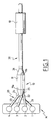
  • la Fig. 1 est une vue schématique d'un dispositif d'évacuation et de traitement des gaz d'échappement d'un moteur à combustion interne, conforme à l'invention,
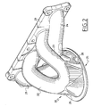
  • la Fig. 2 est une vue en perspective de l'élément de liaison entre le moteur et le pot catalytique conforme à l'invention,
  • la Fig. 3 est une vue en perspective du collecteur d'entrée des gaz d'échappement dans le pot catalytique,
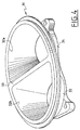
  • la Fig. 4 est une vue en perspective du collecteur de sortie des gaz d'échappement du pot catalytique,
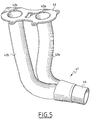
  • la Fig. 5 est une vue en perspective de l'élément de liaison entre le collecteur de sortie du pot catalytique et le pot de détente.
Sur la Fig. 1, on a représenté schématiquement un dispositif d'évacuation et de traitement des gaz d'échappement d'un moteur à combustion interne M comportant par exemple quatre cylindres en ligne, respectivement 1, 2, 3 et 4 dans l'ordre d'allumage.
Le dispositif d'évacuation et de traitement des gaz d'échappement comporte une ligne principale d'échappement-désignée dans son ensemble par la référence 10 et comprenant notamment un pot catalytique 11 et un premier pot de détente 12.
De manière classique, le pot catalytique 11 est constitué par une enveloppe métallique qui contient une structure imprégnée d'un matériau catalyseur déterminant des canaux longitudinaux de circulation pour les gaz d'échappement traversant le pot catalytique.
Les gaz d'échappement sont éliminés par une réaction chimique d'oxydation ou de réduction au contact du catalyseur, dès que celui-ci a été porté par ces gaz d'échappement à une température suffisante pour assurer le démarrage de la réaction chimique.
Le pot catalytique 11 est disposé à proximité des sorties des cylindres du moteur M et son entrée 11a est directement reliée auxdites sorties de ces cylindres par un élément de liaison désigné par la référence générale 20.
La sortie 11b du pot catalytique 11 est raccordée au pot de détente 12 par un élément intermédiaire de liaison désigné par la référence générale 30.
La sortie du pot de détente 12 est reliée au reste de la ligne d'échappement, non représentée.
D'une manière générale, la ligne d'échappement 10 comporte des moyens de séparation des gaz d'échappement en deux flux indépendants jusqu'à l'entrée du pot de détente 12.
L'élément de liaison 20 se compose d'un collecteur 25 dénommé par la suite premier collecteur et de quatre tubulures d'échappement, respectivement 21, 22, 23 et 24, raccordant chaque cylindre 1, 2, 3 et 4 avec le premier collecteur 25.
Sur les sorties des cylindres 1, 2, 3 et 4 est fixée, par exemple par l'intermédiaire d'organes de vissage non représentés, une bride 29 d'extrémité comportant quatre orifices correspondant respectivement aux sortie d'échappement de la culasse du moteur M.
Ces orifices ménagés sur la bride 29 d'extrémité sont reliés au premier collecteur 25 par les tubulures d'échappement 21, 22, 23 et 24, comme représenté à la Fig. 2.
Ainsi que représenté à la Fig. 3, le premier collecteur 25 monté sur l'entrée 11a du pot catalytique 11 comporte une enveloppe 26 délimitant intérieurement deux chambres, respectivement 26a et 26b, qui présentent chacune une conicité divergente vers l'entrée 11a du pot catalytique 11.
La chambre 26a est reliée à un premier groupe de tubulures d'échappement 21 et 24 qui sont raccordées chacune à une sortie d'échappement d'un cylindre, respectivement 1 et 4, et la chambre 26b est reliée à un second groupe de tubulures d'échappement 22 et 23 qui sont raccordées chacune à une sortie d'échappement d'un cylindre, respectivement 2 et 3.
Ainsi, les gaz d'échappement provenant des chambres de combustion des cylindres sont séparés en deux flux indépendants, un premier flux provenant des chambres de combustion des cylindres 1 et 4 convergent vers la chambre de combustion 26a et un second flux provenant des chambres de combustion des cylindres 2 et 3 et convergent vers la chambre 26b du premier collecteur 25, dans le cas où l'ordre d'allumage des cylindres est 1-3-4-2.
En fait, chaque chambre, respectivement 26a et 26b, du premier collecteur 25 est reliée à la sortie de deux des cylindres qui ne se suivent pas dans l'ordre d'allumage.
Comme représenté à la Fig. 3, les chambres 26a et 26b sont séparées par une cloison transversale 27 qui s'étend sur toute la hauteur de l'enveloppe 26.
De préférence, les tubulures d'échappement 21, 22, 23 et 24 et le premier collecteur 25 forment une seule pièce réalisée par exemple par fonderie.
L'enveloppe 26 du premier collecteur 25 comporte un orifice 28 pour l'implantation dans la cloison transversale 27 d'une sonde à oxygène, non représentée.
Dans le cas où une sonde à oxygène est implantée dans chaque chambre 26a et 26b, l'enveloppe 26 est percée de deux orifices débouchant chacun dans une desdites chambres.
L'ensemble constitué par le premier collecteur 25 et les tubulures d'échappement 21, 22, 23 et 24 est fixé sur l'entrée 11a du pot catalytique 11 par des moyens appropriés, non représentés.
L'ensemble de liaison 30 entre la sortie 11b du pot catalytique 11 et l'entrée du pot de détente 12 comporte deux sous ensembles formés respectivement par un collecteur 31 fixé sur la sortie 11b du pot catalytique 11 et dénommé par la suite second collecteur (Fig. 4) et par des tubulures de liaison 41 disposées entre le second collecteur 31 et l'entrée du pot catalytique 12 (Fig. 5).
Le second collecteur 31 représenté à la Fig. 4 comporte une enveloppe 32 délimitant intérieurement deux chambres, respectivement 32a et 32b, séparées l'une de l'autre par une cloison transversale 33 s'étendant sur toute la hauteur de l'enveloppe 32.
Ce second collecteur 31 est fixé sur la sortie 11b du pot catalytique 11 par des moyens appropriés, non représentés, et comporte à son extrémité opposée une bride 34 de raccordement par des organes de vissage, non représentés, avec les tubulures de liaison 41.
Chaque chambre 32a et 32b du second collecteur 31 présente une conicité divergente vers la sortie 11b du pot catalytique 11.
La bride 34 du second collecteur 31 est raccordée à l'élément 41 par une bride 42 comportant deux orifices 42a et 42b reliés respectivement à la chambre 32a et 32b dudit second collecteur 31.
L'élément 41 est formé par une première partie comprenant deux tubulures 43a et 43b s'étendant sur une partie de la longueur dudit élément 41 et une seconde partie formée par une tubulure unique 44 s'étendant sur l'autre partie dudit élément 41.
La tubulure 43a est reliée par l'une de ses extrémités à la chambre 32a du second collecteur 31 et par l'autre de ses extrémités à la tubulure 44 et la tubulure 43b est reliée par l'une de ses extrémités à la chambre 32b dudit second collecteur 31 et par l'autre de ses extrémités à cette tubulure 44 qui est elle-même raccordée à l'entrée du pot de détente 12 par des moyens appropriés, non représentés.
Grâce au dispositif d'évacuation et de traitement selon l'invention, le pot catalytique 11 est placé à proximité du moteur et est relié directement aux sorties des cylindres de ce moteur ce qui permet d'amener rapidement le catalyseur du pot catalytique à une température suffisante pour assurer le démarrage de la réaction chimique.
De plus, le dispositif d'évacuation et de traitement selon l'invention permet de garder la séparation des tubulures d'échappement de façon que l'onde de surpression néfaste ne puisse remonter vers le moteur qu'après un trajet suffisamment long pour la faire arriver après la phase de croisement des soupapes dudit moteur.
En effet, les gaz d'échappement sont séparés en deux flux indépendants.
Un premier flux provenant des cylindres 1 et 4 est canalisé vers la chambre 26a du premier collecteur 25 par les tubulures d'échappement 21 et 24, puis passe par un premier groupe de canaux du pot catalytique 11 et à la sortie de ce pot catalytique 11, le premier flux de gaz d'échappement est canalisé vers le pot de détente 12 par la chambre 32a du second collecteur 31 et la tubulure 43a.
Le second flux de gaz d'échappement provenant des cylindres 2 et 3 est canalisé dans la chambre 26b du premier collecteur 25 par les tubulures d'échappement 22 et 23, puis traverse un second groupe de canaux du pot catalytique 11. A la sortie de ce pot catalytique 11, le second flux de gaz d'échappement traverse la chambre 32b du second collecteur 31 et la tubulure 43b.
Les deux flux sont ensuite regroupés en un seul flux qui est canalisé vers le pot de détente 12 par l'intermédiaire de la tubulure 44.
La conception du dispositif d'évacuation et de traitement des gaz d'échappement selon l'invention présente l'avantage de permettre une implantation du pot catalytique à proximité du moteur et donc d'obtenir une montée en température rapide du catalyseur de ce pot catalytique et également d'éviter une remontée néfaste vers le moteur de l'onde de surpression pendant la phase de croisement des soupapes de ce moteur.
Claims (7)

  1. Dispositif d'évacuation et de traitement des gaz d'échappement d'un moteur à combustion interne, du type comprenant une ligne principale d'échappement (10) reliée par l'une de ses extrémités à la sortie des cylindres (1, 2, 3, 4) du moteur par des tubulures d'échappement (21, 22, 23, 24) et comportant un pot catalytique (11) muni de canaux longitudinaux de circulation desdits gaz et au moins un pot de détente (12), caractérisé en ce que l'entrée (11a) du pot catalytique (11) est raccordée directement aux tubulures d'échappement (21, 22, 23, 24) et la ligne d'échappement (10) comporte des moyens (25 ; 31 ; 43a, 43b) de séparation des gaz d'échappement en deux flux indépendants de la sortie des tubulures d'échappement (21, 22, 23, 24) jusqu'à l'entrée du pot de détente (12).
  2. Dispositif selon la revendication 1, caractérisé en ce que les moyens de séparation sont formés par un premier collecteur (25) monté sur l'entrée (11a) du pot catalytique (11) et comportant deux chambres indépendantes (26a, 26b) reliées chacune d'un côté à un groupe de tubulures d'échappement (21, 24) et de l'autre côté à un groupe de canaux du pot catalytique (11) et par un second collecteur (31) monté sur la sortie (11b) dudit pot catalytique (11) et comportant deux chambres indépendantes (32a, 32b) reliées chacune d'un côté à un groupe de canaux du pot catalytique (11) et de l'autre côté à une tubulure de liaison (43a, 43b) raccordée à l'entrée dudit pot de détente (12).
  3. Dispositif selon la revendication 2, caractérisé en ce que chaque chambre (26a, 26b) du premier collecteur (25) présente une conicité divergente vers l'entrée (11a) du pot catalytique (11).
  4. Dispositif selon la revendication 2, caractérisé en ce que chaque chambre (32a, 32b) du second collecteur (31) présente une conicité divergente vers la sortie (11b) du pot catalytique (11).
  5. Dispositif selon l'une quelconque des revendications 2 à 4, caractérisé en ce que chaque chambre (26a, 26b) du premier collecteur (25) est reliée à la sortie de deux des cylindres (1, 2, 3, 4) qui ne se suivent pas dans l'ordre d'allumage.
  6. Dispositif selon la revendication 5, caractérisé en ce que la chambre (26a) du premier collecteur (25) est reliée aux cylindres (1, 4) et la chambre (26b) dudit premier collecteur (25) est relié aux cylindres (2, 3).
  7. Dispositif selon l'une quelconque des revendications précédentes, caractérisé en ce que les tubulures d'échappement (21, 22, 23, 24) et le premier collecteur (25) forment une seule pièce réalisée par fonderie.
EP01400105A 2000-01-20 2001-01-15 Dispositif d'évacuation et de traitement des gaz d'échappement d'un moteur à combustion interne Withdrawn EP1118750A1 (fr)

Applications Claiming Priority (2)

Application Number Priority Date Filing Date Title
FR0000705 2000-01-20
FR0000705A FR2804165B1 (fr) 2000-01-20 2000-01-20 Dispositif d'evacuation et de traitement des gaz d'echappement d'un moteur a combustion interne

Publications (1)

Publication Number Publication Date
EP1118750A1 true EP1118750A1 (fr) 2001-07-25

Family

ID=8846108

Family Applications (1)

Application Number Title Priority Date Filing Date
EP01400105A Withdrawn EP1118750A1 (fr) 2000-01-20 2001-01-15 Dispositif d'évacuation et de traitement des gaz d'échappement d'un moteur à combustion interne

Country Status (5)

Country Link
EP (1) EP1118750A1 (fr)
JP (1) JP2001241323A (fr)
AR (1) AR027249A1 (fr)
BR (1) BR0100138A (fr)
FR (1) FR2804165B1 (fr)

Cited By (4)

* Cited by examiner, † Cited by third party
Publication number Priority date Publication date Assignee Title
EP1524031A1 (fr) * 2003-10-17 2005-04-20 Ngk Insulators, Ltd. Structure en nid d'abeilles et pot catalytique
EP1726798A3 (fr) * 2005-05-25 2007-04-25 Yamaha Hatsudoki Kabushiki Kaisha Système d'échappement, dispositif pour moteur et véhicule l'utilisant
EP1749987A3 (fr) * 2005-08-05 2007-05-02 Yamaha Hatsudoki Kabushiki Kaisha Système d'échappement, et moteur à combustion interne et véhicule comprenant celui-ci
CN103328783A (zh) * 2011-01-20 2013-09-25 马自达汽车株式会社 用于多气缸引擎的进排气系统

Citations (3)

* Cited by examiner, † Cited by third party
Publication number Priority date Publication date Assignee Title
US5365735A (en) * 1992-08-10 1994-11-22 Ford Motor Company Baffled catalytic converter
EP0753651A1 (fr) * 1995-07-08 1997-01-15 Adam Opel Ag Système d'échappement pour un moteur à combustion interne multicylindre
EP0761939A1 (fr) * 1995-08-16 1997-03-12 General Motors Corporation Convertisseur collecteur

Patent Citations (3)

* Cited by examiner, † Cited by third party
Publication number Priority date Publication date Assignee Title
US5365735A (en) * 1992-08-10 1994-11-22 Ford Motor Company Baffled catalytic converter
EP0753651A1 (fr) * 1995-07-08 1997-01-15 Adam Opel Ag Système d'échappement pour un moteur à combustion interne multicylindre
EP0761939A1 (fr) * 1995-08-16 1997-03-12 General Motors Corporation Convertisseur collecteur

Cited By (9)

* Cited by examiner, † Cited by third party
Publication number Priority date Publication date Assignee Title
EP1524031A1 (fr) * 2003-10-17 2005-04-20 Ngk Insulators, Ltd. Structure en nid d'abeilles et pot catalytique
US7438868B2 (en) 2003-10-17 2008-10-21 Ngk Insulators, Ltd. Honeycomb structure and catalytic converter
EP1726798A3 (fr) * 2005-05-25 2007-04-25 Yamaha Hatsudoki Kabushiki Kaisha Système d'échappement, dispositif pour moteur et véhicule l'utilisant
US7418818B2 (en) 2005-05-25 2008-09-02 Yamaha Hatsudoki Kabushiki Kaisha Exhaust system, and engine device and vehicle with the same
EP1749987A3 (fr) * 2005-08-05 2007-05-02 Yamaha Hatsudoki Kabushiki Kaisha Système d'échappement, et moteur à combustion interne et véhicule comprenant celui-ci
US7454901B2 (en) 2005-08-05 2008-11-25 Yamaha Hatsudoki Kabushiki Kaisha Exhaust system, and engine device and vehicle with the same
CN103328783A (zh) * 2011-01-20 2013-09-25 马自达汽车株式会社 用于多气缸引擎的进排气系统
US9188095B2 (en) 2011-01-20 2015-11-17 Mazda Motor Corporation Intake and exhaust system for multi-cylinder engine
CN103328783B (zh) * 2011-01-20 2016-05-25 马自达汽车株式会社 进排气系统

Also Published As

Publication number Publication date
JP2001241323A (ja) 2001-09-07
FR2804165A1 (fr) 2001-07-27
AR027249A1 (es) 2003-03-19
BR0100138A (pt) 2001-08-28
FR2804165B1 (fr) 2002-12-06

Similar Documents

Publication Publication Date Title
FR2540177A1 (fr) Regeneration des filtres catalytiques a particules et appareil pour sa mise en oeuvre
WO2012052672A1 (fr) Ligne d&#39;échappement pour véhicule automobile.
FR2714696A1 (fr) Procédé pour réduire des émissions d&#39;hydrocarbures d&#39;un moteur à combustion interne et dispositif pour la mise en Óoeuvre de ce procédé.
FR2902137A1 (fr) Bruleur et procede pour la regeneration de cartouches de filtration et dispositifs equipes d&#39;un tel bruleur
FR2928176A1 (fr) Procede de regeneration d&#39;un filtre a particules pour moteur a essence et ensemble d&#39;echappement associe
EP0718479B1 (fr) Dispositif de traitement des gaz d&#39;échappement d&#39;un moteur à allumage commandé comportant un corps catalyseur et un adsorbeur d&#39;hydrocarbures disposés à l&#39;intérieur d&#39;un collecteur d&#39;échappement
EP1118750A1 (fr) Dispositif d&#39;évacuation et de traitement des gaz d&#39;échappement d&#39;un moteur à combustion interne
FR2598176A1 (fr) Silencieux pour courant gazeux
FR3107304A1 (fr) Dispositif catalytique pour traitement des gaz d’echappement d’un moteur a combustion interne
EP0718478B1 (fr) Dispositif de traitement des gaz d&#39;échappement d&#39;un moteur à allumage par compression comportant un catalyseur et un adsorbeur d&#39;oxydes d&#39;azote placés dans le collecteur d&#39;échappement
FR2488653A1 (fr) Moteur a combustion interne
FR2752880A1 (fr) Dispositif de suralimentation pour moteur a combustion interne
FR2881793A1 (fr) Moteur alternatif a combustion interne et procede d&#39;elimination des particules des gaz brules pour un tel moteur alternatif
EP0431985B1 (fr) Dispositif d&#39;évacuation et de traitement anti-pollution de gaz d&#39;échappement d&#39;un moteur
TWI805635B (zh) 用於二衝程引擎及對應之機動車輛之排氣系統
EP1914400B1 (fr) Ligne d&#39;échappement pourvue d&#39;un pot catalytique et d&#39;une sonde de température
FR2948412A1 (fr) Ligne d&#39;echappement avec un vaporisateur de carburant monte sur le collecteur
FR2488329A1 (fr) Pot d&#39;echappement de moteur a deux temps
FR2731044A1 (fr) Dispositif d&#39;echappement pour moteur a combustion interne
WO2002094415A1 (fr) Procede de nettoyage de la face amont d&#39;un filtre a particules
FR2926597A1 (fr) Systeme de traitement de gaz d&#39;echappement d&#39;un moteur a combustion interne de vehicule automobile et procede associe
FR2796984A1 (fr) Systeme de regeneration d&#39;un piege a oxydes d&#39;azote
FR2935740A3 (fr) Buse d&#39;injection de vapeur de carburant equipee de deux ouvertures d&#39;injection
FR2777319A1 (fr) Dispositif d&#39;epuration de gaz d&#39;echappement, notamment de moteurs a combustion interne
FR2902827A1 (fr) Dispositif d&#39;echappement comportant une culasse munie d&#39;un collecteur d&#39;echappement integre decouple thermiquement

Legal Events

Date Code Title Description
PUAI Public reference made under article 153(3) epc to a published international application that has entered the european phase

Free format text: ORIGINAL CODE: 0009012

AK Designated contracting states

Kind code of ref document: A1

Designated state(s): AT BE CH CY DE DK ES FI FR GB GR IE IT LI LU MC NL PT SE TR

AX Request for extension of the european patent

Free format text: AL;LT;LV;MK;RO;SI

17P Request for examination filed

Effective date: 20011224

AKX Designation fees paid

Free format text: AT BE CH CY DE DK ES FI FR GB GR IE IT LI LU MC NL PT SE TR

17Q First examination report despatched

Effective date: 20040708

STAA Information on the status of an ep patent application or granted ep patent

Free format text: STATUS: THE APPLICATION IS DEEMED TO BE WITHDRAWN

18D Application deemed to be withdrawn

Effective date: 20051027