EP1118131B1 - Method of forming a terminal pip protrusion on the casing of an alkaline cell - Google Patents
Method of forming a terminal pip protrusion on the casing of an alkaline cell Download PDFInfo
- Publication number
- EP1118131B1 EP1118131B1 EP99942433A EP99942433A EP1118131B1 EP 1118131 B1 EP1118131 B1 EP 1118131B1 EP 99942433 A EP99942433 A EP 99942433A EP 99942433 A EP99942433 A EP 99942433A EP 1118131 B1 EP1118131 B1 EP 1118131B1
- Authority
- EP
- European Patent Office
- Prior art keywords
- casing
- cathode material
- elongated member
- cell
- housing
- Prior art date
- Legal status (The legal status is an assumption and is not a legal conclusion. Google has not performed a legal analysis and makes no representation as to the accuracy of the status listed.)
- Expired - Lifetime
Links
Images

Classifications
-
- H—ELECTRICITY
- H01—ELECTRIC ELEMENTS
- H01M—PROCESSES OR MEANS, e.g. BATTERIES, FOR THE DIRECT CONVERSION OF CHEMICAL ENERGY INTO ELECTRICAL ENERGY
- H01M6/00—Primary cells; Manufacture thereof
- H01M6/005—Devices for making primary cells
-
- H—ELECTRICITY
- H01—ELECTRIC ELEMENTS
- H01M—PROCESSES OR MEANS, e.g. BATTERIES, FOR THE DIRECT CONVERSION OF CHEMICAL ENERGY INTO ELECTRICAL ENERGY
- H01M10/00—Secondary cells; Manufacture thereof
- H01M10/24—Alkaline accumulators
- H01M10/28—Construction or manufacture
- H01M10/283—Cells or batteries with two cup-shaped or cylindrical collectors
-
- H—ELECTRICITY
- H01—ELECTRIC ELEMENTS
- H01M—PROCESSES OR MEANS, e.g. BATTERIES, FOR THE DIRECT CONVERSION OF CHEMICAL ENERGY INTO ELECTRICAL ENERGY
- H01M6/00—Primary cells; Manufacture thereof
- H01M6/04—Cells with aqueous electrolyte
- H01M6/06—Dry cells, i.e. cells wherein the electrolyte is rendered non-fluid
- H01M6/08—Dry cells, i.e. cells wherein the electrolyte is rendered non-fluid with cup-shaped electrodes
- H01M6/085—Dry cells, i.e. cells wherein the electrolyte is rendered non-fluid with cup-shaped electrodes of the reversed type, i.e. anode in the centre
-
- H—ELECTRICITY
- H01—ELECTRIC ELEMENTS
- H01M—PROCESSES OR MEANS, e.g. BATTERIES, FOR THE DIRECT CONVERSION OF CHEMICAL ENERGY INTO ELECTRICAL ENERGY
- H01M50/00—Constructional details or processes of manufacture of the non-active parts of electrochemical cells other than fuel cells, e.g. hybrid cells
- H01M50/10—Primary casings; Jackets or wrappings
- H01M50/102—Primary casings; Jackets or wrappings characterised by their shape or physical structure
- H01M50/107—Primary casings; Jackets or wrappings characterised by their shape or physical structure having curved cross-section, e.g. round or elliptic
-
- H—ELECTRICITY
- H01—ELECTRIC ELEMENTS
- H01M—PROCESSES OR MEANS, e.g. BATTERIES, FOR THE DIRECT CONVERSION OF CHEMICAL ENERGY INTO ELECTRICAL ENERGY
- H01M50/00—Constructional details or processes of manufacture of the non-active parts of electrochemical cells other than fuel cells, e.g. hybrid cells
- H01M50/50—Current conducting connections for cells or batteries
- H01M50/543—Terminals
- H01M50/552—Terminals characterised by their shape
- H01M50/559—Terminals adapted for cells having curved cross-section, e.g. round, elliptic or button cells
-
- Y—GENERAL TAGGING OF NEW TECHNOLOGICAL DEVELOPMENTS; GENERAL TAGGING OF CROSS-SECTIONAL TECHNOLOGIES SPANNING OVER SEVERAL SECTIONS OF THE IPC; TECHNICAL SUBJECTS COVERED BY FORMER USPC CROSS-REFERENCE ART COLLECTIONS [XRACs] AND DIGESTS
- Y02—TECHNOLOGIES OR APPLICATIONS FOR MITIGATION OR ADAPTATION AGAINST CLIMATE CHANGE
- Y02E—REDUCTION OF GREENHOUSE GAS [GHG] EMISSIONS, RELATED TO ENERGY GENERATION, TRANSMISSION OR DISTRIBUTION
- Y02E60/00—Enabling technologies; Technologies with a potential or indirect contribution to GHG emissions mitigation
- Y02E60/10—Energy storage using batteries
-
- Y—GENERAL TAGGING OF NEW TECHNOLOGICAL DEVELOPMENTS; GENERAL TAGGING OF CROSS-SECTIONAL TECHNOLOGIES SPANNING OVER SEVERAL SECTIONS OF THE IPC; TECHNICAL SUBJECTS COVERED BY FORMER USPC CROSS-REFERENCE ART COLLECTIONS [XRACs] AND DIGESTS
- Y02—TECHNOLOGIES OR APPLICATIONS FOR MITIGATION OR ADAPTATION AGAINST CLIMATE CHANGE
- Y02P—CLIMATE CHANGE MITIGATION TECHNOLOGIES IN THE PRODUCTION OR PROCESSING OF GOODS
- Y02P70/00—Climate change mitigation technologies in the production process for final industrial or consumer products
- Y02P70/50—Manufacturing or production processes characterised by the final manufactured product
-
- Y—GENERAL TAGGING OF NEW TECHNOLOGICAL DEVELOPMENTS; GENERAL TAGGING OF CROSS-SECTIONAL TECHNOLOGIES SPANNING OVER SEVERAL SECTIONS OF THE IPC; TECHNICAL SUBJECTS COVERED BY FORMER USPC CROSS-REFERENCE ART COLLECTIONS [XRACs] AND DIGESTS
- Y10—TECHNICAL SUBJECTS COVERED BY FORMER USPC
- Y10T—TECHNICAL SUBJECTS COVERED BY FORMER US CLASSIFICATION
- Y10T29/00—Metal working
- Y10T29/49—Method of mechanical manufacture
- Y10T29/49002—Electrical device making
- Y10T29/49108—Electric battery cell making
Definitions
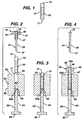
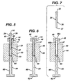
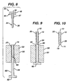
- the invention relates to a method of forming a terminal pip protrusion on the cylindrical casing of an electrochemical cell, particularly an alkaline cell having an anode comprising zinc and cathode comprising manganese dioxide.
- the invention relates to loading the cell with cathode active material while simultaneously forming a terminal pip protrusion on the cell casing.
- EP 0 420 404 discloses a cathode and casing assembly for dry cell batteries including the alkaline type.
- the casing has a cylindrical shape and is typically fabricated from a suitable metal, such as steel.
- the casing has a circular closed end which typically includes an outwardly projecting positive terminal in the form of a generally circular deformation, bulge, or pip for engaging the positive contact in an electrically operated device.
- the other end of the casing is initially open, and the casing is positioned so that the open end opens downwardly over the lower die assembly receiving chamber.
- the terminal projects upwardly, and the retracted upper die assembly anvil rod preferably includes a recess for accommodating the terminal when the rod is subsequently lowered to engage the casing.
- the method of the invention may be applied to forming a positive pip protrusion at the closed end of the cylindrical casing of an electrochemical cell.
- the cell to which the method of the invention has particularly utility is an alkaline cell having a cylindrical casing initially formed with a closed end and an open end and having an anode comprising zinc, a cathode comprising manganese dioxide, and an alkaline electrolyte.
- the method of the invention is not intended to be restricted to application to any particular cell size.
- the end cap assembly 10 of the invention is not intended to be restricted to any particular alkaline cell chemistry and/or alkaline cell size. Such representative chemistries, for example, are disclosed in U.S. Patent 5,401,590 herein incorporated by reference.
- the method of the invention while illustrated with respect to a AAAA (Quad A) alkaline cell is not intended to be restricted to cell size and may be equally applicable to forming the positive pip protrusion (pip protrusion at the closed end of the casing) of AAA, AA, C, and D size alkaline cells.
- Separator 70 may be composed of ion porous separator material conventionally employed in alkaline cells, for example, of cellulosic or rayon material.
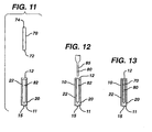
- Anode material 80 which may be in the form of a wet slurry may then be injected into central cavity (anode cavity) 82 by employing a slurry pump having an outlet nozzle 85.
- the anode material 80 may be in the form of a gelled mixture containing mercury free (zero-added mercury) zinc alloy powder.
- Such mixture may typically contain aqueous KOH electrolyte solution, gelling agent, e.g. acrylic acid copolymer such as CARBOPOL C940 from B.F.
- An end cap assembly 90 comprising a plastic insulating disk 92, end cap 95 with metal current collector 94 welded thereto is inserted into the open end 12 of casing 10.
- End cap 95 may have one or more vent holes 98 in its surface and plastic insulating disk 92 may comprise an integrally disposed thin region 97 which functions as a rupturable membrane which is designed to rupture if gas build up within the cell reaches a predetermined value.
- the peripheral edge 17 of casing 10 may be crimped over the peripheral edge 96 of insulating disk 92 and the peripheral edge 98 of end cap 95 by applying methods described in U.S. Patent 5,150,602 herein incorporated by reference.
Landscapes
- Engineering & Computer Science (AREA)
- Manufacturing & Machinery (AREA)
- Chemical & Material Sciences (AREA)
- Chemical Kinetics & Catalysis (AREA)
- Electrochemistry (AREA)
- General Chemical & Material Sciences (AREA)
- Primary Cells (AREA)
- Connection Of Batteries Or Terminals (AREA)
- Sealing Battery Cases Or Jackets (AREA)
- Battery Electrode And Active Subsutance (AREA)
Abstract
Description
Claims (24)
- A method for forming a terminal pip protrusion on a cylindrical casing for an alkaline electrochemical cell having a cathode comprising manganese dioxide, comprising the steps of:whereby as said elongated member pushes against said cathode material, the cathode material becomes compacted and simultaneously therewith a portion of the outside surface of said casing is pushed into said depression forming a pip protrusion on said casing.providing a cylindrical casing having cathode material contained therein and pushing a portion of an elongated member against said cathode material, said casing operatively contacting an adjacent surface having a depression formed therein,
- A method for forming a terminal pip protrusion at the closed end of a cylindrical casing for an alkaline electrochemical cell having a cathode comprising manganese dioxide, comprising the steps of:whereby as said elongated member is pushed into said cathode material, the cathode material becomes compacted and simultaneously therewith a portion of said outside surface of said casing is pushed into said depression forming a pip protrusion at the closed end of said casing.a) providing a cylindrical casing having a closed end and a cathode material contained within said casing;b) applying a surface having a depression therein against a portion of the outside surface of the closed end of said casing;c) pushing an elongated member into said cathode material so that it penetrates through at least a portion of said cathode material;
- The method of claim 2, further comprising the step of:d) applying means for preventing cathode material from moving beyond a predetermined level along the length of said casing as said elongated member is pushed into said cathode material.
- The method of claim 2, wherein the depression is aligned with about the center of the closed end of the casing and the elongated member has a maximum diameter less than the inside diameter of said casing.
- The method of claim 2, wherein the closed end of the casing in step (a) is flat or has a pip protrusion of smaller size than the pip protrusion formed in step (c).
- The method of claim 3, wherein the means for preventing the cathode material from moving beyond a predetermined level along the length of said casing comprises a housing placed at the open end of said casing and a portion of said housing penetrates into said casing a predetermined distance along the length of said casing.
- The method of claim 6, wherein said housing has a cavity therethrough and said elongated member is inserted into the cathode material through said cavity.
- The method of claim 7, wherein the housing has an upper portion and a lower portion wherein the width of the lower portion is less than the width of the upper portion and wherein said cavity runs through both the upper and lower portions of said housing and wherein the housing is placed at the open end of casing with the lower portion closer to the cathode material than the upper portion.
- The method of claim 8, wherein the housing is inserted into the open end of said casing so that the lower portion of the housing penetrates into the casing a predetermined distance from the open end of the casing.
- The method of claim 9, wherein a portion of the cavity through the upper portion of the housing has a diameter greater than the diameter of the cavity through the lower portion of said housing.
- The method of claim 10, wherein the upper portion of the housing is provided with a seat within the cavity therethrough and said elongated member has an end portion having a diameter greater than the diameter of the body of said elongated member, wherein force is applied to the elongated member to push it into said cathode material until said seat engages said end portion to prevent said elongated member from penetrating further into said cathode material.
- The method of claim 11, wherein the elongated member is in the configuration of a nail.
- The method of claim 7, wherein the elongated member is inserted into said cathode material without contacting any portion of said surface having a depression therein.
- The method of claim 2, comprising the step of inserting the casing into a channel within the a holding member prior to inserting said elongated member into the cathode material.
- The method of claim 14, wherein the surface having said depression is located at the end of an anvil.
- The method of claim 15, comprising the step of inserting said anvil into said channel within the holding member so that said depression is adjacent the closed end of said casing.
- The method of claim 3, wherein at least a major amount of the cathode material becomes compacted within an annular region within the casing, said annular region being between the inside longitudinal surface of the casing and the surface of the portion of the elongated member penetrating into the cathode material.
- The method of claim 17, further comprising the step of removing the elongated member from the casing after the cathode material has been compacted and the pip protrusion at the closed end of said casing formed; inserting a separator material into the casing so that it contacts the exposed surface of said compacted cathode material; and inserting anode material into the central region of the casing to fill the space occupied by said elongated member.
- The method of claim 18, further comprising the step of inserting an end cap assembly into the open end of the casing after the step of inserting said anode material and crimping the peripheral edge of the casing over the peripheral edge of the end cap assembly to form a sealed cell, said end cap assembly comprising an insulating disk, a terminal end cap over the insulating disk and an elongated current collector in electrical contact with the terminal end cap.
- The method of claim 2, wherein the casing is of size corresponding to the casing size for an AAAA (QUAD A) cell.
- The method of claim 20, wherein the elongated member is inserted into the cathode material with a force of between about 1000 and 2000 pounds (4440 and 8900 Newtons).
- The method of claim 20, wherein the casing has a thickness of between about 0.1 and 0.25 mm, and the formed pip protrusion has a height of about 1.3 mm and an inside diameter of between about 2.6 mm.
- The method of claim 2, wherein the portion of said elongated member penetrating said cathode material has a configuration selected from the group consisting of cylinder, cone, truncated cone, and polyhedron.
- The method of claim 2, wherein the portion of said elongated member penetrating said cathode material has a cylindrical configuration.
Applications Claiming Priority (3)
| Application Number | Priority Date | Filing Date | Title |
|---|---|---|---|
| US141095 | 1998-08-27 | ||
| US09/141,095 US6126704A (en) | 1998-08-27 | 1998-08-27 | Method of forming a terminal pip protrusion on the casing of an alkaline cell |
| PCT/US1999/019210 WO2000013246A1 (en) | 1998-08-27 | 1999-08-24 | Method of forming a terminal pip protrusion on the casing of an alkaline cell |
Publications (2)
| Publication Number | Publication Date |
|---|---|
| EP1118131A1 EP1118131A1 (en) | 2001-07-25 |
| EP1118131B1 true EP1118131B1 (en) | 2005-11-02 |
Family
ID=22494131
Family Applications (1)
| Application Number | Title | Priority Date | Filing Date |
|---|---|---|---|
| EP99942433A Expired - Lifetime EP1118131B1 (en) | 1998-08-27 | 1999-08-24 | Method of forming a terminal pip protrusion on the casing of an alkaline cell |
Country Status (9)
| Country | Link |
|---|---|
| US (1) | US6126704A (en) |
| EP (1) | EP1118131B1 (en) |
| JP (1) | JP2002524820A (en) |
| CN (1) | CN1312960A (en) |
| AT (1) | ATE308804T1 (en) |
| AU (1) | AU5581299A (en) |
| CA (1) | CA2337073A1 (en) |
| DE (1) | DE69928118T2 (en) |
| WO (1) | WO2000013246A1 (en) |
Families Citing this family (5)
| Publication number | Priority date | Publication date | Assignee | Title |
|---|---|---|---|---|
| US6371567B1 (en) * | 1999-03-22 | 2002-04-16 | The Sollami Company | Bit holders and bit blocks for road milling, mining and trenching equipment |
| CN1639894A (en) * | 2002-02-15 | 2005-07-13 | 永备电池有限公司 | Cylindrical alkaline cells with increased discharge performance |
| US20140183798A1 (en) * | 2012-12-28 | 2014-07-03 | Smith International, Inc. | Manufacture of cutting elements having lobes |
| CN106029265B (en) * | 2013-12-23 | 2018-12-14 | 史密斯国际有限公司 | Production of cutting elements with protrusions |
| US10784519B2 (en) * | 2018-03-02 | 2020-09-22 | Energizer Brands, Llc | Electrochemical cell with electrode filled protrusion |
Family Cites Families (12)
| Publication number | Priority date | Publication date | Assignee | Title |
|---|---|---|---|---|
| JPS566381A (en) * | 1979-06-28 | 1981-01-22 | Toshiba Battery Co Ltd | Manufacturing method of alkaline cell |
| US4679316A (en) * | 1985-03-04 | 1987-07-14 | Fremont Special Machine Co., Inc. | Apparatus for forming and inserting cell separator baskets |
| JPS62234876A (en) * | 1986-04-04 | 1987-10-15 | Sharp Corp | Manufacture of battery |
| CA1306284C (en) * | 1987-08-24 | 1992-08-11 | Karl V. Kordesch | Metal and metal oxide catalyzed electrodes for electrochemical cells, and methods of making same |
| CA1295364C (en) * | 1988-07-08 | 1992-02-04 | Battery Technologies Inc. | Rechargeable alkaline manganese cells with zinc anodes |
| US5036581A (en) * | 1989-09-29 | 1991-08-06 | Weiler Engineering, Inc. | Dry cell battery casing processing |
| US5108852A (en) * | 1990-03-23 | 1992-04-28 | Battery Technologies Inc. | Manganese dioxide cathode for a rechargeable alkaline cell, and cell containing the same |
| US5150602A (en) * | 1990-09-10 | 1992-09-29 | Duracell Inc. | Crimping method for electrochemical cells |
| US5324332A (en) * | 1992-10-30 | 1994-06-28 | Rayovac Corporation | Alkaline manganese dioxide cells |
| EP0614239A3 (en) * | 1993-03-01 | 1996-10-16 | Tadiran Ltd | Non-aqueous safe secondary cell. |
| JPH0955212A (en) * | 1995-08-10 | 1997-02-25 | Sony Corp | Alkaline battery and manufacturing method thereof |
| JP3671551B2 (en) * | 1996-09-10 | 2005-07-13 | 東洋製罐株式会社 | Battery can and method for producing dry battery using the can |
-
1998
- 1998-08-27 US US09/141,095 patent/US6126704A/en not_active Expired - Lifetime
-
1999
- 1999-08-24 CA CA002337073A patent/CA2337073A1/en not_active Abandoned
- 1999-08-24 CN CN99809425A patent/CN1312960A/en active Pending
- 1999-08-24 WO PCT/US1999/019210 patent/WO2000013246A1/en not_active Ceased
- 1999-08-24 AU AU55812/99A patent/AU5581299A/en not_active Abandoned
- 1999-08-24 JP JP2000568132A patent/JP2002524820A/en active Pending
- 1999-08-24 EP EP99942433A patent/EP1118131B1/en not_active Expired - Lifetime
- 1999-08-24 DE DE69928118T patent/DE69928118T2/en not_active Expired - Lifetime
- 1999-08-24 AT AT99942433T patent/ATE308804T1/en not_active IP Right Cessation
Also Published As
| Publication number | Publication date |
|---|---|
| WO2000013246A1 (en) | 2000-03-09 |
| DE69928118D1 (en) | 2005-12-08 |
| EP1118131A1 (en) | 2001-07-25 |
| US6126704A (en) | 2000-10-03 |
| JP2002524820A (en) | 2002-08-06 |
| DE69928118T2 (en) | 2006-07-20 |
| CN1312960A (en) | 2001-09-12 |
| AU5581299A (en) | 2000-03-21 |
| CA2337073A1 (en) | 2000-03-09 |
| ATE308804T1 (en) | 2005-11-15 |
Similar Documents
| Publication | Publication Date | Title |
|---|---|---|
| CN1233048C (en) | A method for preparing an electrochemical cell casing | |
| US5667912A (en) | Current collector assembly for an electrochemical cell | |
| EP1104585B1 (en) | End cap assembly for an alkaline cell | |
| CA2350945A1 (en) | Alkaline cell with improved cathode | |
| US6025090A (en) | End cap assembly for an alkaline cell | |
| EP1093671B1 (en) | Electrochemical cell formed with big mouth open end can | |
| US6007936A (en) | Battery | |
| US6495284B2 (en) | End seal assembly for an alkaline cell | |
| EP1118131B1 (en) | Method of forming a terminal pip protrusion on the casing of an alkaline cell | |
| US3554813A (en) | Method for sealing an electrochemical cell | |
| EP4177981A1 (en) | A holder for an electrode of a button battery and a battery provided therewith | |
| US20240363931A1 (en) | Electrochemical cell with anode material in protrusion | |
| JP2025065793A (en) | Battery and battery manufacturing method | |
| JP2609620B2 (en) | Manufacturing method of cylindrical alkaline battery | |
| JPS6329796B2 (en) | ||
| JPH0437546B2 (en) | ||
| MXPA01004927A (en) | Alkaline cell with improved cathode | |
| HK1032486B (en) | Electrochemical cell formed with big mouth open end can | |
| JPH1145708A (en) | Method of forming positive electrode mixture for alkaline dry battery |
Legal Events
| Date | Code | Title | Description |
|---|---|---|---|
| PUAI | Public reference made under article 153(3) epc to a published international application that has entered the european phase |
Free format text: ORIGINAL CODE: 0009012 |
|
| 17P | Request for examination filed |
Effective date: 20010223 |
|
| AK | Designated contracting states |
Kind code of ref document: A1 Designated state(s): AT BE CH CY DE DK ES FI FR GB GR IE IT LI LU MC NL PT SE |
|
| AX | Request for extension of the european patent |
Free format text: AL;LT;LV;MK;RO;SI |
|
| 17Q | First examination report despatched |
Effective date: 20020722 |
|
| GRAP | Despatch of communication of intention to grant a patent |
Free format text: ORIGINAL CODE: EPIDOSNIGR1 |
|
| GRAS | Grant fee paid |
Free format text: ORIGINAL CODE: EPIDOSNIGR3 |
|
| GRAA | (expected) grant |
Free format text: ORIGINAL CODE: 0009210 |
|
| AK | Designated contracting states |
Kind code of ref document: B1 Designated state(s): AT BE CH CY DE DK ES FI FR GB GR IE IT LI LU MC NL PT SE |
|
| PG25 | Lapsed in a contracting state [announced via postgrant information from national office to epo] |
Ref country code: NL Free format text: LAPSE BECAUSE OF FAILURE TO SUBMIT A TRANSLATION OF THE DESCRIPTION OR TO PAY THE FEE WITHIN THE PRESCRIBED TIME-LIMIT Effective date: 20051102 Ref country code: LI Free format text: LAPSE BECAUSE OF FAILURE TO SUBMIT A TRANSLATION OF THE DESCRIPTION OR TO PAY THE FEE WITHIN THE PRESCRIBED TIME-LIMIT Effective date: 20051102 Ref country code: IT Free format text: LAPSE BECAUSE OF FAILURE TO SUBMIT A TRANSLATION OF THE DESCRIPTION OR TO PAY THE FEE WITHIN THE PRESCRIBED TIME-LIMIT;WARNING: LAPSES OF ITALIAN PATENTS WITH EFFECTIVE DATE BEFORE 2007 MAY HAVE OCCURRED AT ANY TIME BEFORE 2007. THE CORRECT EFFECTIVE DATE MAY BE DIFFERENT FROM THE ONE RECORDED. Effective date: 20051102 Ref country code: FI Free format text: LAPSE BECAUSE OF FAILURE TO SUBMIT A TRANSLATION OF THE DESCRIPTION OR TO PAY THE FEE WITHIN THE PRESCRIBED TIME-LIMIT Effective date: 20051102 Ref country code: CH Free format text: LAPSE BECAUSE OF FAILURE TO SUBMIT A TRANSLATION OF THE DESCRIPTION OR TO PAY THE FEE WITHIN THE PRESCRIBED TIME-LIMIT Effective date: 20051102 Ref country code: AT Free format text: LAPSE BECAUSE OF FAILURE TO SUBMIT A TRANSLATION OF THE DESCRIPTION OR TO PAY THE FEE WITHIN THE PRESCRIBED TIME-LIMIT Effective date: 20051102 |
|
| RAP1 | Party data changed (applicant data changed or rights of an application transferred) |
Owner name: DURACELL INC. |
|
| REG | Reference to a national code |
Ref country code: GB Ref legal event code: FG4D |
|
| REG | Reference to a national code |
Ref country code: CH Ref legal event code: EP |
|
| REF | Corresponds to: |
Ref document number: 69928118 Country of ref document: DE Date of ref document: 20051208 Kind code of ref document: P |
|
| PG25 | Lapsed in a contracting state [announced via postgrant information from national office to epo] |
Ref country code: SE Free format text: LAPSE BECAUSE OF FAILURE TO SUBMIT A TRANSLATION OF THE DESCRIPTION OR TO PAY THE FEE WITHIN THE PRESCRIBED TIME-LIMIT Effective date: 20060202 Ref country code: GR Free format text: LAPSE BECAUSE OF FAILURE TO SUBMIT A TRANSLATION OF THE DESCRIPTION OR TO PAY THE FEE WITHIN THE PRESCRIBED TIME-LIMIT Effective date: 20060202 Ref country code: DK Free format text: LAPSE BECAUSE OF FAILURE TO SUBMIT A TRANSLATION OF THE DESCRIPTION OR TO PAY THE FEE WITHIN THE PRESCRIBED TIME-LIMIT Effective date: 20060202 |
|
| PG25 | Lapsed in a contracting state [announced via postgrant information from national office to epo] |
Ref country code: ES Free format text: LAPSE BECAUSE OF FAILURE TO SUBMIT A TRANSLATION OF THE DESCRIPTION OR TO PAY THE FEE WITHIN THE PRESCRIBED TIME-LIMIT Effective date: 20060213 |
|
| PG25 | Lapsed in a contracting state [announced via postgrant information from national office to epo] |
Ref country code: PT Free format text: LAPSE BECAUSE OF FAILURE TO SUBMIT A TRANSLATION OF THE DESCRIPTION OR TO PAY THE FEE WITHIN THE PRESCRIBED TIME-LIMIT Effective date: 20060403 |
|
| NLV1 | Nl: lapsed or annulled due to failure to fulfill the requirements of art. 29p and 29m of the patents act | ||
| REG | Reference to a national code |
Ref country code: CH Ref legal event code: PL |
|
| PG25 | Lapsed in a contracting state [announced via postgrant information from national office to epo] |
Ref country code: IE Free format text: LAPSE BECAUSE OF NON-PAYMENT OF DUE FEES Effective date: 20060824 |
|
| PG25 | Lapsed in a contracting state [announced via postgrant information from national office to epo] |
Ref country code: MC Free format text: LAPSE BECAUSE OF NON-PAYMENT OF DUE FEES Effective date: 20060831 |
|
| PLBE | No opposition filed within time limit |
Free format text: ORIGINAL CODE: 0009261 |
|
| STAA | Information on the status of an ep patent application or granted ep patent |
Free format text: STATUS: NO OPPOSITION FILED WITHIN TIME LIMIT |
|
| 26N | No opposition filed |
Effective date: 20060803 |
|
| EN | Fr: translation not filed | ||
| PG25 | Lapsed in a contracting state [announced via postgrant information from national office to epo] |
Ref country code: FR Free format text: LAPSE BECAUSE OF FAILURE TO SUBMIT A TRANSLATION OF THE DESCRIPTION OR TO PAY THE FEE WITHIN THE PRESCRIBED TIME-LIMIT Effective date: 20061222 |
|
| REG | Reference to a national code |
Ref country code: IE Ref legal event code: MM4A |
|
| BECA | Be: change of holder's address |
Owner name: THE *GILLETTE CYPRUDENTIAL TOWER BUILDING, US-BOST Effective date: 20051102 |
|
| BECH | Be: change of holder |
Owner name: THE *GILLETTE CY Effective date: 20051102 |
|
| REG | Reference to a national code |
Ref country code: GB Ref legal event code: 732E |
|
| PG25 | Lapsed in a contracting state [announced via postgrant information from national office to epo] |
Ref country code: LU Free format text: LAPSE BECAUSE OF NON-PAYMENT OF DUE FEES Effective date: 20060824 |
|
| PG25 | Lapsed in a contracting state [announced via postgrant information from national office to epo] |
Ref country code: FR Free format text: LAPSE BECAUSE OF FAILURE TO SUBMIT A TRANSLATION OF THE DESCRIPTION OR TO PAY THE FEE WITHIN THE PRESCRIBED TIME-LIMIT Effective date: 20051102 Ref country code: CY Free format text: LAPSE BECAUSE OF FAILURE TO SUBMIT A TRANSLATION OF THE DESCRIPTION OR TO PAY THE FEE WITHIN THE PRESCRIBED TIME-LIMIT Effective date: 20051102 |
|
| PGFP | Annual fee paid to national office [announced via postgrant information from national office to epo] |
Ref country code: GB Payment date: 20090708 Year of fee payment: 11 Ref country code: DE Payment date: 20090831 Year of fee payment: 11 |
|
| GBPC | Gb: european patent ceased through non-payment of renewal fee |
Effective date: 20100824 |
|
| REG | Reference to a national code |
Ref country code: DE Ref legal event code: R119 Ref document number: 69928118 Country of ref document: DE Effective date: 20110301 |
|
| PG25 | Lapsed in a contracting state [announced via postgrant information from national office to epo] |
Ref country code: DE Free format text: LAPSE BECAUSE OF NON-PAYMENT OF DUE FEES Effective date: 20110301 |
|
| PG25 | Lapsed in a contracting state [announced via postgrant information from national office to epo] |
Ref country code: GB Free format text: LAPSE BECAUSE OF NON-PAYMENT OF DUE FEES Effective date: 20100824 |
|
| PGFP | Annual fee paid to national office [announced via postgrant information from national office to epo] |
Ref country code: BE Payment date: 20160725 Year of fee payment: 18 |
|
| REG | Reference to a national code |
Ref country code: BE Ref legal event code: PD Owner name: DURACELL U.S. OPERATIONS, INC.; US Free format text: DETAILS ASSIGNMENT: CHANGE OF OWNER(S), AFFECTATION / CESSION Effective date: 20161024 Ref country code: BE Ref legal event code: MM Effective date: 20170831 |
|
| PG25 | Lapsed in a contracting state [announced via postgrant information from national office to epo] |
Ref country code: BE Free format text: LAPSE BECAUSE OF NON-PAYMENT OF DUE FEES Effective date: 20170831 |