EP1117959B1 - Coupling assembly - Google Patents
Coupling assembly Download PDFInfo
- Publication number
- EP1117959B1 EP1117959B1 EP99948343A EP99948343A EP1117959B1 EP 1117959 B1 EP1117959 B1 EP 1117959B1 EP 99948343 A EP99948343 A EP 99948343A EP 99948343 A EP99948343 A EP 99948343A EP 1117959 B1 EP1117959 B1 EP 1117959B1
- Authority
- EP
- European Patent Office
- Prior art keywords
- coupling assembly
- coupling
- male
- adjacent
- male coupling
- Prior art date
- Legal status (The legal status is an assumption and is not a legal conclusion. Google has not performed a legal analysis and makes no representation as to the accuracy of the status listed.)
- Expired - Lifetime
Links
- 230000008878 coupling Effects 0.000 title claims description 113
- 238000010168 coupling process Methods 0.000 title claims description 113
- 238000005859 coupling reaction Methods 0.000 title claims description 113
- 238000007789 sealing Methods 0.000 claims description 11
- 238000003780 insertion Methods 0.000 claims description 4
- 230000037431 insertion Effects 0.000 claims description 4
- 239000002184 metal Substances 0.000 description 9
- 239000003507 refrigerant Substances 0.000 description 7
- 239000012530 fluid Substances 0.000 description 3
- 238000004378 air conditioning Methods 0.000 description 2
- 238000004891 communication Methods 0.000 description 1
- 239000007788 liquid Substances 0.000 description 1
- 238000012986 modification Methods 0.000 description 1
- 230000004048 modification Effects 0.000 description 1
- 230000000007 visual effect Effects 0.000 description 1
Images




Classifications
-
- F—MECHANICAL ENGINEERING; LIGHTING; HEATING; WEAPONS; BLASTING
- F16—ENGINEERING ELEMENTS AND UNITS; GENERAL MEASURES FOR PRODUCING AND MAINTAINING EFFECTIVE FUNCTIONING OF MACHINES OR INSTALLATIONS; THERMAL INSULATION IN GENERAL
- F16L—PIPES; JOINTS OR FITTINGS FOR PIPES; SUPPORTS FOR PIPES, CABLES OR PROTECTIVE TUBING; MEANS FOR THERMAL INSULATION IN GENERAL
- F16L29/00—Joints with fluid cut-off means
- F16L29/005—Joints with fluid cut-off means joints with cut-off devices which can be perforated
-
- F—MECHANICAL ENGINEERING; LIGHTING; HEATING; WEAPONS; BLASTING
- F16—ENGINEERING ELEMENTS AND UNITS; GENERAL MEASURES FOR PRODUCING AND MAINTAINING EFFECTIVE FUNCTIONING OF MACHINES OR INSTALLATIONS; THERMAL INSULATION IN GENERAL
- F16L—PIPES; JOINTS OR FITTINGS FOR PIPES; SUPPORTS FOR PIPES, CABLES OR PROTECTIVE TUBING; MEANS FOR THERMAL INSULATION IN GENERAL
- F16L39/00—Joints or fittings for double-walled or multi-channel pipes or pipe assemblies
-
- F—MECHANICAL ENGINEERING; LIGHTING; HEATING; WEAPONS; BLASTING
- F16—ENGINEERING ELEMENTS AND UNITS; GENERAL MEASURES FOR PRODUCING AND MAINTAINING EFFECTIVE FUNCTIONING OF MACHINES OR INSTALLATIONS; THERMAL INSULATION IN GENERAL
- F16L—PIPES; JOINTS OR FITTINGS FOR PIPES; SUPPORTS FOR PIPES, CABLES OR PROTECTIVE TUBING; MEANS FOR THERMAL INSULATION IN GENERAL
- F16L41/00—Branching pipes; Joining pipes to walls
- F16L41/08—Joining pipes to walls or pipes, the joined pipe axis being perpendicular to the plane of a wall or to the axis of another pipe
- F16L41/086—Joining pipes to walls or pipes, the joined pipe axis being perpendicular to the plane of a wall or to the axis of another pipe fixed with screws
-
- Y—GENERAL TAGGING OF NEW TECHNOLOGICAL DEVELOPMENTS; GENERAL TAGGING OF CROSS-SECTIONAL TECHNOLOGIES SPANNING OVER SEVERAL SECTIONS OF THE IPC; TECHNICAL SUBJECTS COVERED BY FORMER USPC CROSS-REFERENCE ART COLLECTIONS [XRACs] AND DIGESTS
- Y10—TECHNICAL SUBJECTS COVERED BY FORMER USPC
- Y10S—TECHNICAL SUBJECTS COVERED BY FORMER USPC CROSS-REFERENCE ART COLLECTIONS [XRACs] AND DIGESTS
- Y10S604/00—Surgery
- Y10S604/905—Aseptic connectors or couplings, e.g. frangible, piercable
Definitions
- the present invention relates generally to a coupling assembly. More specifically, the invention is directed to a unitary coupling assembly for use with refrigerant lines.
- Refrigerant couplings are known in the art see for example US-A-3,202,442 and US-A-5,374,101 . These types of couplings are used to connect suction lines and liquid lines between indoor and outdoor units of a split-type air conditioning system.
- the coupling assembly of the present invention is comprised of a unitary female coupling that includes at least two passageways.
- Each passageway includes a first end adapted to receive a male coupling half and a second end adapted to receive a line.
- Each passageway includes an annular sealing surface located adjacent to the first end.
- An annular seal is positioned in an annular groove defined by each passageway adjacent to the first end.
- a frangible female diaphragm is positioned in each passageway adjacent to the annular seal.
- a cutting device is positioned in each passageway adjacent to the female diaphragm.
- a line is positioned in the passageway adjacent to the second end.
- the coupling assembly further includes a male coupling portion having at least two male coupling halves.
- Each of the coupling halves includes a leading end for insertion in the first end of a corresponding passageway of the female body and a trailing end adapted to receive a line.
- Each coupling half includes a bore that extends between the leading and trailing ends.
- a frangible male diaphragm is positioned in each bore adjacent to the leading end.
- An annular sealing surface is located on each coupling half for engaging a corresponding annular sealing edge of the female body to form a metal-to-metal seal therebetween upon full connection.
- a line is positioned in the bore adjacent to the trailing end.
- the coupling assembly includes a bracket for securing the male coupling portion to the female body.
- a fastening device such as a threaded bolt, extends through the bracket, the male coupling portion and the, female body. As the bolt is torqued or tightened, the bracket engages the male coupling portion to cause it to move toward the female body until the male coupling halves of the male coupling portion are fully inserted in the passageways. The bracket and the bolt maintain the placement of the male coupling portion with respect to the female body.
- Another object of the present invention is to provide a fastening device for a coupling assembly that is difficult to over torque.
- the coupling assembly 10 includes a unitary female body 12 formed of metal that includes at least two cylindrical passageways 14 and 16.
- the passageways 14 and 16 can either have different diameters as shown in Fig. 2 or identical diameters depending on the application.
- Each passageway 14 and 16 includes a first end 18 and a second end 20.
- An annular sealing edge 22 is positioned adjacent to the first end 18 of each passageway 14 and 16.
- An annular seal 24 is positioned in an annular groove 25 formed in each passageway 14 and 16 adjacent to the first end 18.
- a frangible metal female diaphragm 26 is positioned in each passageway 14 and 16 adjacent to the annular seal 24 and has an annular sidewall 27 soldered or brazed to the inside surface of each passageway 14 and 16. The end of the sidewall 27 engages a shoulder 29 in each passageway 14 and 16.
- a metal cutting device 28 having a sharp edge 30 is positioned in each passageway 14 and 16 adjacent to the female diaphragm 26. The size and shape of the cutting device 28 is determined by the diameter of the passageway in which it is positioned.
- the cutting device 28 has an annular flange 33 at the end opposite the cutting edge 30 which rests against a shoulder 31 of the female body 12 adjacent to each passageway 14 and 16.
- a first line 32 is positioned in the first passageway 14 adjacent to the second end 20.
- a second line 34 is positioned in the second passageway 16 adjacent to the second end 20.
- the female body 12 includes two mounting flanges 36 and 38. Each of the mounting flanges 36 and 38 includes an opening 40 for receiving, for example, a threaded bolt (not shown) to attach the female body 12 to, for example, an outside unit of a split-type air conditioning system (not shown).
- the female body 12 includes a threaded opening 42.
- the coupling assembly 10 includes a male coupling portion 50 including a first male coupling half 52 and a separate second male coupling half 54.
- the first and second coupling halves 52 and 54 are formed of metal.
- Each coupling half 52 and 54 includes a leading end 56, a trailing end 58 and a cylindrical bore 60 extending between the leading and trailing ends 56 and 58.
- the leading ends 56 of the first and second male coupling halves 52 and 54 are sized and configured for insertion in the first ends 18 of the first and second passageways 14 and 16, respectively.
- Each coupling half 52 and 54 includes a frangible metal male diaphragm 62 positioned in the bore 60 adjacent to the leading end 56.
- Each diaphragm 62 has an annular sidewall 63 soldered or brazed to the inside surface of its respective bore 60 in the area adjacent to the leading end 56. The end of the sidewall 63 engages a shoulder 65 spaced from the leading end 56.
- Each coupling half 52 and 54 includes an annular sealing surface 64 sized and configured for engagement with a corresponding annular sealing edge 22 of the female body 12. Still referring to Fig. 2, the first male coupling half 52 includes a third line 66 positioned in the bore 60 adjacent to the trailing end 58. The second male coupling half 54 includes a fourth line 68 positioned in the bore 60 adjacent to the trailing end 58. As shown in Fig. 2, each coupling half 52 and 54 includes an annular shoulder 70.
- the coupling assembly 10 includes a metal bracket 80 having a first recess 82 and a second recess 84.
- the first recess 82 receives the first male coupling half 52 and the second recess 84 receives the second male coupling half 54.
- each recess 82 and 84 includes a stop 86 that is sized and configured to receive a corresponding annular shoulder 70 of the first and second male coupling halves 52 and 54.
- the bracket 80 defines an opening 88.
- the coupling assembly 10 includes a threaded bolt 90 having a head 92 that defines a tool recess 94.
- the bolt 90 extends through the opening 88 and further includes a threaded portion 96 that is sized and configured to be received by the threaded opening 42 of the female body 12.
- the intended use of the coupling assembly 10 will be described.
- the first, second, third and fourth lines 32, 34, 66 and 68 are precharged with refrigerant.
- the female and male diaphragms 26 and 62 prevent the escape of refrigerant from the lines 32, 34, 66 and 68.
- the female body 12 is connected to the male coupling portion 50 by the insertion of the first and second male coupling halves 52 and 54 into the first ends 18 of the first and second passageways 14 and 16, respectively.
- the bracket 80 is positioned adjacent to the annular shoulders 70 of the first and second male coupling halves 52 and 54.
- the bolt 90 is inserted through the opening 88 of the bracket 80 and into the threaded opening 42 of the female body 12.
- a tightening tool such as a wrench (not shown) is inserted into the tool recess 94 of the head 92 of the bolt 90.
- the bolt 90 is then torqued so that the threaded portion 96 of the bolt 90 engages the threaded opening 42 to draw the bracket 80 toward the female body 12.
- the stops 86 of the bracket 80 engage the annular shoulders 70 of the first and second male coupling halves 52 and 54 to cause them to be in axial alignment with the first and second passageways 14 and 16.
- the bolt 90 is torqued until the bracket 80 causes the annular sealing surfaces 64 of the first and second male coupling halves 52 and 54 to engage the corresponding annular sealing edges 22 of the female body 12.
- This provides "metal-to-metal" seals between the female body 12 and the first and second male coupling halves 52 and 54.
- the annular seals 24 maintain seals between the exterior surfaces 98 of the first and second male coupling halves 52 and 54 and the first and second passageways 14 and 16 of the female body 12 to prevent leakage of refrigerant during connection.
- a second embodiment coupling assembly 110 is shown in Figs. 4- 6.
- the coupling assembly 110 includes the elements described above with respect to the first embodiment coupling assembly 10.
- the male coupling portion 50 is unitary.
- the male coupling portion 50 includes an opening 112 for receiving the bolt 90.
- the bracket 80 includes a first opening 114 and a second opening 116 that are sized and configured to receive the trailing ends 58 of the first and second coupling halves 52 and 54.
- the bracket 80 includes a center portion 118 that is bowed.
- the head 92 of the bolt 90 engages the center portion 118 and forces it toward the male coupling portion 50 so that the bracket becomes flush with an exterior surface 120 of the male coupling portion 50 to equally distribute the clamping force on the male coupling portion 50 and to provide a visual indication that the bolt 90 has been properly torqued.
- a third embodiment coupling assembly 210 is shown in Figs. 7 and 8.
- the coupling assembly 210 includes the elements described above with respect to the first embodiment coupling assembly 10.
- the female body 12 has a first side 212 and a second side 214.
- the first side 212 includes a recess 216.
- the male coupling portion 50 includes a projection 218 that is received by the recess 216 of the female body 12. This ensures the proper alignment of the female body 12 with respect to the male coupling portion 50.
- the coupling assembly 210 further includes a frangible head 220 having an unthreaded top portion 222 and a threaded bottom portion 224.
- the unthreaded top portion 222 has an inwardly facing wall surface 223 spaced from the bolt 90.
- An annular slot 226 partially divides the top portion 222 from the bottom portion 224.
- a washer 228 is positioned in the slot 226.
- the head 220 has a predetermined torque value as determined by the depth of the slot 226 and the thickness of the metal between the radially innermost portion of the slot 226 and the wall surface 223 so that once the proper amount of torque has been applied to the head 220, the top portion 222 breaks away from the bottom portion 224.
Landscapes
- Engineering & Computer Science (AREA)
- General Engineering & Computer Science (AREA)
- Mechanical Engineering (AREA)
- Filling Or Discharging Of Gas Storage Vessels (AREA)
- Quick-Acting Or Multi-Walled Pipe Joints (AREA)
- Connection Of Plates (AREA)
- Joints That Cut Off Fluids, And Hose Joints (AREA)
Description
- The present invention relates generally to a coupling assembly. More specifically, the invention is directed to a unitary coupling assembly for use with refrigerant lines. Refrigerant couplings are known in the art see for example
US-A-3,202,442 andUS-A-5,374,101 . These types of couplings are used to connect suction lines and liquid lines between indoor and outdoor units of a split-type air conditioning system. - It has been found that there are problems associated with the prior art refrigerant couplings. For example, the coupling halves of the prior art couplings become misaligned thereby causing the improper opening of the diaphragms which can result in blockage of the fluid flow path through the coupling or the presence of loose pieces of the diaphragms in the system. It has also been found that some prior art couplings include fastening or attachment devices that can be over torqued resulting in damage to the couplings.
- In view of the foregoing, there is a need for a coupling assembly that provides for the proper alignment of the coupling halves during assembly. There is also a need for a coupling assembly that has a fastening device that cannot be over corqued. The present invention satisfies these needs. The present invention allows for the relatively quick and easy connection of two or more lines at once with proper alignment of the lines.
- It is an object of the present invention to satisfy the before mentioned needs. Thus it is the primary object of the present invention to provide an improved coupling assembly that simplifies connection and ensures proper alignment of male coupling portion with a female body.
- The coupling assembly of the present invention, as it is defined by claim 1, is comprised of a unitary female coupling that includes at least two passageways. Each passageway includes a first end adapted to receive a male coupling half and a second end adapted to receive a line. Each passageway includes an annular sealing surface located adjacent to the first end. An annular seal is positioned in an annular groove defined by each passageway adjacent to the first end. A frangible female diaphragm is positioned in each passageway adjacent to the annular seal. A cutting device is positioned in each passageway adjacent to the female diaphragm. A line is positioned in the passageway adjacent to the second end.
- The coupling assembly further includes a male coupling portion having at least two male coupling halves. Each of the coupling halves includes a leading end for insertion in the first end of a corresponding passageway of the female body and a trailing end adapted to receive a line. Each coupling half includes a bore that extends between the leading and trailing ends. A frangible male diaphragm is positioned in each bore adjacent to the leading end. An annular sealing surface is located on each coupling half for engaging a corresponding annular sealing edge of the female body to form a metal-to-metal seal therebetween upon full connection. A line is positioned in the bore adjacent to the trailing end. The coupling assembly includes a bracket for securing the male coupling portion to the female body. A fastening device, such as a threaded bolt, extends through the bracket, the male coupling portion and the, female body. As the bolt is torqued or tightened, the bracket engages the male coupling portion to cause it to move toward the female body until the male coupling halves of the male coupling portion are fully inserted in the passageways. The bracket and the bolt maintain the placement of the male coupling portion with respect to the female body.
- Another object of the present invention is to provide a fastening device for a coupling assembly that is difficult to over torque.
- Other objects and advantages of the present invention will become apparent to those skilled in the art upon a review of the following detailed description of the preferred embodiments and the accompanying drawings.
-
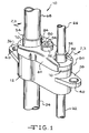
- Fig. 1 is a perspective view of a first embodiment coupling assembly according to the present invention;
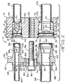
- Fig. 2 is a cross-sectional view taken through the center of the first embodiment coupling assembly according to the present invention with the female body separated from the male coupling portion;
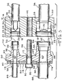
- Fig. 3 is a view similar to the view of Fig. 2 showing the female body joined to the male coupling portion;
- Fig. 4 is a perspective view of a second embodiment coupling assembly according to the present invention;
- Fig. 5 is a cross-sectional view taken through the center of the second embodiment coupling assembly according to the present invention with the female body separated from the male coupling portion;
- Fig. 6 is a view similar to the view of Fig. 5 showing the female body joined to the male coupling portion;
- Fig. 7 is a perspective view of a third embodiment coupling assembly according to the present invention; and
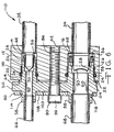
- Fig. 8 is a cross-sectional view of the third embodiment coupling assembly according to the present invention showing the female body joined to the male coupling portion.
- The preferred embodiments and best mode of the present invention will now be described in detail with reference being made to the drawings. Referring to Figs. 1-3, a first
embodiment coupling assembly 10 is shown. Thecoupling assembly 10 includes a unitaryfemale body 12 formed of metal that includes at least twocylindrical passageways passageways passageway first end 18 and asecond end 20. Anannular sealing edge 22 is positioned adjacent to thefirst end 18 of eachpassageway annular seal 24 is positioned in anannular groove 25 formed in eachpassageway first end 18. A frangible metalfemale diaphragm 26 is positioned in eachpassageway annular seal 24 and has anannular sidewall 27 soldered or brazed to the inside surface of eachpassageway sidewall 27 engages ashoulder 29 in eachpassageway metal cutting device 28 having asharp edge 30 is positioned in eachpassageway female diaphragm 26. The size and shape of thecutting device 28 is determined by the diameter of the passageway in which it is positioned. Thecutting device 28 has anannular flange 33 at the end opposite thecutting edge 30 which rests against ashoulder 31 of thefemale body 12 adjacent to eachpassageway - A
first line 32 is positioned in thefirst passageway 14 adjacent to thesecond end 20. Asecond line 34 is positioned in thesecond passageway 16 adjacent to thesecond end 20. As shown in Fig. 1, thefemale body 12 includes twomounting flanges mounting flanges female body 12 to, for example, an outside unit of a split-type air conditioning system (not shown). As shown in Fig. 2, thefemale body 12 includes a threadedopening 42. - Still referring to Figs. 1-3, the
coupling assembly 10 includes amale coupling portion 50 including a firstmale coupling half 52 and a separate secondmale coupling half 54. The first andsecond coupling halves coupling half end 56, atrailing end 58 and acylindrical bore 60 extending between the leading andtrailing ends ends 56 of the first and secondmale coupling halves first ends 18 of the first andsecond passageways coupling half male diaphragm 62 positioned in thebore 60 adjacent to theleading end 56. Eachdiaphragm 62 has anannular sidewall 63 soldered or brazed to the inside surface of itsrespective bore 60 in the area adjacent to theleading end 56. The end of thesidewall 63 engages ashoulder 65 spaced from the leadingend 56. Eachcoupling half annular sealing surface 64 sized and configured for engagement with a corresponding annular sealingedge 22 of thefemale body 12. Still referring to Fig. 2, the firstmale coupling half 52 includes athird line 66 positioned in thebore 60 adjacent to the trailingend 58. The secondmale coupling half 54 includes afourth line 68 positioned in thebore 60 adjacent to the trailingend 58. As shown in Fig. 2, eachcoupling half annular shoulder 70. - Referring to Figs. 1-3, the
coupling assembly 10 includes ametal bracket 80 having afirst recess 82 and asecond recess 84. Thefirst recess 82 receives the firstmale coupling half 52 and thesecond recess 84 receives the secondmale coupling half 54. As shown in Fig. 2, eachrecess stop 86 that is sized and configured to receive a correspondingannular shoulder 70 of the first and second male coupling halves 52 and 54. As shown in Fig. 2, thebracket 80 defines anopening 88. - Still referring to Figs. 1-3, the
coupling assembly 10 includes a threadedbolt 90 having ahead 92 that defines atool recess 94. Thebolt 90 extends through theopening 88 and further includes a threadedportion 96 that is sized and configured to be received by the threadedopening 42 of thefemale body 12. - Referring to Fig. 3, the intended use of the
coupling assembly 10 will be described. Prior to the connection of thefemale body 12 with themale coupling portion 50, the first, second, third andfourth lines male diaphragms lines female body 12 is connected to themale coupling portion 50 by the insertion of the first and second male coupling halves 52 and 54 into the first ends 18 of the first andsecond passageways bracket 80 is positioned adjacent to theannular shoulders 70 of the first and second male coupling halves 52 and 54. Thebolt 90 is inserted through theopening 88 of thebracket 80 and into the threadedopening 42 of thefemale body 12. A tightening tool, such as a wrench (not shown), is inserted into thetool recess 94 of thehead 92 of thebolt 90. Thebolt 90 is then torqued so that the threadedportion 96 of thebolt 90 engages the threadedopening 42 to draw thebracket 80 toward thefemale body 12. The stops 86 of thebracket 80 engage theannular shoulders 70 of the first and second male coupling halves 52 and 54 to cause them to be in axial alignment with the first andsecond passageways - Still referring to Fig. 3, as the first and second male coupling halves 52 and 54 are moved into the first and
second passageways sharp edges 30 of thecutting devices 28 of thefemale body 12 engage first thefemale diaphragms 26 and then themale diaphragms 62 to cause thediaphragms respective passageways second passageways female body 12 to be in fluid communication with thebores 60 of the first and second male coupling halves 52 and 54. Accordingly, this allows for the movement of refrigerant through the first, second, third andfourth lines - As shown in Fig. 3, the
bolt 90 is torqued until thebracket 80 causes the annular sealing surfaces 64 of the first and second male coupling halves 52 and 54 to engage the corresponding annular sealing edges 22 of thefemale body 12. This provides "metal-to-metal" seals between thefemale body 12 and the first and second male coupling halves 52 and 54. Theannular seals 24 maintain seals between theexterior surfaces 98 of the first and second male coupling halves 52 and 54 and the first andsecond passageways female body 12 to prevent leakage of refrigerant during connection. - A second
embodiment coupling assembly 110 is shown in Figs. 4-6. Thecoupling assembly 110 includes the elements described above with respect to the firstembodiment coupling assembly 10. In thecoupling assembly 110, themale coupling portion 50 is unitary. Themale coupling portion 50 includes anopening 112 for receiving thebolt 90. Thebracket 80 includes afirst opening 114 and asecond opening 116 that are sized and configured to receive the trailing ends 58 of the first and second coupling halves 52 and 54. As shown in Fig. 5, thebracket 80 includes acenter portion 118 that is bowed. As shown in Fig. 6, thehead 92 of thebolt 90 engages thecenter portion 118 and forces it toward themale coupling portion 50 so that the bracket becomes flush with anexterior surface 120 of themale coupling portion 50 to equally distribute the clamping force on themale coupling portion 50 and to provide a visual indication that thebolt 90 has been properly torqued. - A third
embodiment coupling assembly 210 is shown in Figs. 7 and 8. Thecoupling assembly 210 includes the elements described above with respect to the firstembodiment coupling assembly 10. In thecoupling assembly 210 thefemale body 12 has afirst side 212 and asecond side 214. Thefirst side 212 includes arecess 216. Themale coupling portion 50 includes aprojection 218 that is received by therecess 216 of thefemale body 12. This ensures the proper alignment of thefemale body 12 with respect to themale coupling portion 50. - Still referring to Figs. 7 and 8, the
coupling assembly 210 further includes afrangible head 220 having an unthreadedtop portion 222 and a threadedbottom portion 224. The unthreadedtop portion 222 has an inwardly facingwall surface 223 spaced from thebolt 90. Anannular slot 226 partially divides thetop portion 222 from thebottom portion 224. Awasher 228 is positioned in theslot 226. When thefemale body 12 is connected to themale coupling portion 50, a wrench (not shown) engages thetop portion 222. Thewasher 228 prevents contact between the wrench and thebottom portion 224. Thehead 220 has a predetermined torque value as determined by the depth of theslot 226 and the thickness of the metal between the radially innermost portion of theslot 226 and thewall surface 223 so that once the proper amount of torque has been applied to thehead 220, thetop portion 222 breaks away from thebottom portion 224. - The above detailed description of the present invention is given for explanatory purposes. It will be apparent to those skilled in the art that numerous changes and modifications can be made without departing from the scope of the invention. Accordingly, the whole of the foregoing description is to be construed in an illustrative and not a limitative sense, the scope of the invention being defined solely by the appended claims.
Claims (10)
- A coupling assembly (10), comprising:(A) a unitary female body (12) including at least two passageways (14,16), each of said passageways including:(i) a first end (18) adapted to receive a male coupling half (52;54) and a second end (20) adapted to receive a conduit (32;34):(ii) an annular sealing edge (22) positioned adjacent to said first end;(iii)an annular seal (24) positioned in said passageway adjacent to said first end;(iv) a frangible female diaphragm (26) positioned in said passageway adjacent to said annular seal;(v) cutting means (28) positioned in said passageway adjacent to said female diaphragm (26) for cutting said female diaphragm;(vi) a conduit (32;34) positioned in said passageway (14;16) adjacent to said second end (20);(B) a male coupling member (50) including at least two male coupling halves (52,54), each of said coupling halves including;(i)a leading end (56) for insertion in said first end of said passageway and a trailing end (58) adapted to receive a second conduit (66,68), a bore (60) extending between said leading and trailing ends;(ii)a frangible male diaphragm (62) positioned in said bore adjacent to said leading end;(iii) an annular sealing surface (64) positioned on said male coupling member for engaging said annular sealing edge surface (22) to form a seal therebetween;(iv) a second conduit (66) positioned in said bore (60) adjacent to said trailing end;(C) a bracket (80) including at least two recesses (82,84) for receiving said at least two male coupling halves (52,54) for securing said male coupling member to said female body; and(D) fastening means (90,92) for fastening said bracket on said coupling assembly.
- The coupling assembly of claim 1, wherein each of said passageways (14,16) is substantially cylindrical.
- The coupling assembly of claim 2, wherein said passageways (14, 16) have different diameters.
- The coupling assembly of claim 2, wherein said passageways (14,16) have substantially identical diameters.
- The coupling assembly of claim 1, wherein said male coupling member (50) is unitary.
- The coupling assembly of claims 1, wherein each of said coupling halves (52,54) further includes an annular shoulder (70).
- The coupling assembly of claim 6, wherein said bracket (80) includes stops (86) for engaging said annular shoulders (70).
- The coupling assembly of claim 1, wherein said bracket (80) includes a bowed center portion (118) prior to securement of said male coupling member (50) to said female body (12).
- The coupling assembly of claim 1, wherein said fastening means consists of a threaded bolt (90) extending through said bracket (80) into a threaded opening (42) included on said female body (12).
- The coupling assembly of claim 9, wherein said bolt (90) includes a frangible head (220) having an unthreaded top portion (222) and a threaded bottom portion (224).
Applications Claiming Priority (5)
| Application Number | Priority Date | Filing Date | Title |
|---|---|---|---|
| US397397 | 1995-03-02 | ||
| US10275198P | 1998-10-02 | 1998-10-02 | |
| US102751P | 1998-10-02 | ||
| US09/397,397 US6382678B1 (en) | 1998-10-02 | 1999-09-16 | Coupling assembly |
| PCT/US1999/021730 WO2000020792A1 (en) | 1998-10-02 | 1999-09-22 | Coupling assembly |
Publications (2)
| Publication Number | Publication Date |
|---|---|
| EP1117959A1 EP1117959A1 (en) | 2001-07-25 |
| EP1117959B1 true EP1117959B1 (en) | 2007-07-18 |
Family
ID=26799694
Family Applications (1)
| Application Number | Title | Priority Date | Filing Date |
|---|---|---|---|
| EP99948343A Expired - Lifetime EP1117959B1 (en) | 1998-10-02 | 1999-09-22 | Coupling assembly |
Country Status (8)
| Country | Link |
|---|---|
| US (1) | US6481756B1 (en) |
| EP (1) | EP1117959B1 (en) |
| JP (1) | JP2002526736A (en) |
| CN (1) | CN1321232A (en) |
| AU (1) | AU6154699A (en) |
| DE (1) | DE69936591T2 (en) |
| EG (1) | EG21943A (en) |
| WO (1) | WO2000020792A1 (en) |
Families Citing this family (52)
| Publication number | Priority date | Publication date | Assignee | Title |
|---|---|---|---|---|
| DE10051606A1 (en) * | 2000-10-18 | 2002-05-02 | Loi Thermprocess Gmbh | Method and device for annealing pipes |
| US6834893B2 (en) | 2001-11-01 | 2004-12-28 | Visteon Global Technologies, Inc. | Peanut fittings for CO2 air conditioning systems |
| GB2382391B (en) * | 2001-11-01 | 2004-10-13 | Visteon Global Tech Inc | Peanut fittings for CO2 air conditioning systems |
| US6676167B2 (en) * | 2002-05-20 | 2004-01-13 | Visteon Global Technologies, Inc. | Air conditioning block fitting with two surface sealing |
| US20050017503A1 (en) * | 2003-07-23 | 2005-01-27 | Garry Tsaur | Connector with frangible seal |
| US6896298B2 (en) * | 2003-08-01 | 2005-05-24 | Paccar Inc | Conduit coupling assembly |
| US7464966B2 (en) * | 2004-06-30 | 2008-12-16 | Tokai Rubber Industries, Inc. | Through-panel fixing device for piping member |
| US7472557B2 (en) * | 2004-12-27 | 2009-01-06 | Carrier Corporation | Automatic refrigerant charging apparatus |
| US7552596B2 (en) * | 2004-12-27 | 2009-06-30 | Carrier Corporation | Dual thermochromic liquid crystal temperature sensing for refrigerant charge indication |
| US20060138772A1 (en) * | 2004-12-27 | 2006-06-29 | Carrier Corporation | Braze-free connector |
| US20060137369A1 (en) * | 2004-12-27 | 2006-06-29 | Carrier Corporation | Single sensor three-step refrigerant charge indicator |
| US20060138771A1 (en) * | 2004-12-27 | 2006-06-29 | Carrier Corporation | Braze-free connector for joining a pair of flow lines |
| US7712319B2 (en) | 2004-12-27 | 2010-05-11 | Carrier Corporation | Refrigerant charge adequacy gauge |
| US7610765B2 (en) | 2004-12-27 | 2009-11-03 | Carrier Corporation | Refrigerant charge status indication method and device |
| SE0500494L (en) * | 2005-03-04 | 2005-12-13 | Novaseptic Ab | Method and apparatus for tightly interconnecting the ends of elongated elements such as hoses or lines |
| US7591485B2 (en) * | 2005-07-11 | 2009-09-22 | Simmons Tom M | Connections for tubing and method of connecting tubing segments |
| US7419192B2 (en) * | 2005-07-13 | 2008-09-02 | Carrier Corporation | Braze-free connector utilizing a sealant coated ferrule |
| DE102005055046A1 (en) * | 2005-11-16 | 2007-05-24 | J. Eberspächer GmbH & Co. KG | Crosstalk for an exhaust system |
| US8186691B2 (en) * | 2006-02-17 | 2012-05-29 | Parker-Hannifin Corporation | Composite seal and coupling |
| JP2007315482A (en) * | 2006-05-25 | 2007-12-06 | Calsonic Kansei Corp | Piping joint |
| US8221363B2 (en) | 2006-10-18 | 2012-07-17 | Baxter Healthcare S.A. | Luer activated device with valve element under tension |
| US7981090B2 (en) | 2006-10-18 | 2011-07-19 | Baxter International Inc. | Luer activated device |
| US7753338B2 (en) | 2006-10-23 | 2010-07-13 | Baxter International Inc. | Luer activated device with minimal fluid displacement |
| US9568226B2 (en) * | 2006-12-20 | 2017-02-14 | Carrier Corporation | Refrigerant charge indication |
| US8290722B2 (en) | 2006-12-20 | 2012-10-16 | Carrier Corporation | Method for determining refrigerant charge |
| US8251087B2 (en) * | 2007-03-12 | 2012-08-28 | Automatic Bar Controls, Inc. | Modular fittings and assemblies for fluid switching |
| KR101206811B1 (en) * | 2007-07-26 | 2012-11-30 | 삼성전자주식회사 | hermetic compressor |
| FR2933155B1 (en) * | 2008-06-30 | 2010-08-27 | Staubli Sa Ets | CONNECTION ASSEMBLY AND METHOD FOR CONNECTING SUCH AN ASSEMBLY |
| US8833803B2 (en) * | 2011-03-31 | 2014-09-16 | Denso International America, Inc. | Connecting block |
| GB2505132A (en) | 2011-06-08 | 2014-02-19 | Nxstage Medical Inc | Methods, devices, and systems for coupling fluid lines |
| US9759465B2 (en) | 2011-12-27 | 2017-09-12 | Carrier Corporation | Air conditioner self-charging and charge monitoring system |
| US9199691B2 (en) * | 2012-08-03 | 2015-12-01 | Shimano Inc. | Hydraulic bicycle component kit |
| US9227692B2 (en) | 2012-08-03 | 2016-01-05 | Shimano Inc. | Hydraulic bicycle component system |
| US9550546B2 (en) * | 2012-08-03 | 2017-01-24 | Shimano Inc. | Hydraulic bicycle hose structure |
| US10131339B2 (en) | 2012-08-03 | 2018-11-20 | Shimano Inc. | Hydraulic bicycle component |
| US9777878B2 (en) | 2012-08-31 | 2017-10-03 | Hanon Systems | Connector |
| US10164373B1 (en) * | 2013-03-15 | 2018-12-25 | Koolance, Inc. | Automatic engagement system for liquid or power connections |
| US8820351B1 (en) * | 2013-06-25 | 2014-09-02 | Chilldyne, Inc. | No drip hot swap connector and method of use |
| EA201690512A1 (en) * | 2013-09-02 | 2016-07-29 | Аборра Аг | HOSE SYSTEM FOR BREAKDOWN |
| DE112016002972T5 (en) * | 2015-07-01 | 2018-03-15 | Denso Corporation | Pair of fasteners |
| DE202016100195U1 (en) * | 2016-01-15 | 2016-02-01 | Ti Automotive Engineering Centre (Heidelberg) Gmbh | Connecting arrangement for an air conditioner |
| US9963192B2 (en) * | 2016-02-01 | 2018-05-08 | Shimano Inc. | Non-metallic bracket for a bicycle hydraulic component |
| US11353145B2 (en) * | 2016-07-18 | 2022-06-07 | Nissan North America, Inc. | Seal member for a hydraulic fluid actuator |
| CN107387918A (en) * | 2017-07-21 | 2017-11-24 | 珠海格力电器股份有限公司 | Connection structure of filter element group spare and water route board reaches purifier including it |
| DE102017222604A1 (en) | 2017-12-13 | 2019-06-13 | Bayerische Motoren Werke Aktiengesellschaft | Plug connection, method for producing a line arrangement and cooling system |
| CN108561653A (en) * | 2018-06-27 | 2018-09-21 | 绵阳创格科技有限公司 | A kind of Multichannel device of fast assembling-disassembling |
| JP2020055194A (en) * | 2018-10-01 | 2020-04-09 | セイコーエプソン株式会社 | Liquid ejection device |
| US12135104B2 (en) | 2019-04-09 | 2024-11-05 | Nxstage Medical, Inc. | Methods, devices, and systems for coupling fluid lines |
| DE102019004659A1 (en) * | 2019-07-02 | 2021-01-07 | Bomag Gmbh | VALVE LOCKING FOR HYDRAULIC HOSE COUPLINGS, CONSTRUCTION MACHINE AND PROCESS |
| EP4425022A3 (en) | 2019-09-12 | 2025-03-12 | A. Raymond Et Cie | Flow control valve and system for cleaning a vehicle surface |
| US12202446B2 (en) | 2019-09-12 | 2025-01-21 | A. Raymond Et Cie | Flow control valve and system for cleaning a vehicle surface |
| GB2612089B (en) * | 2021-10-21 | 2024-10-30 | Mark Vince Fenson | Pipe interconnector |
Family Cites Families (25)
| Publication number | Priority date | Publication date | Assignee | Title |
|---|---|---|---|---|
| US3202442A (en) * | 1961-05-19 | 1965-08-24 | Aeroquip Corp | Coupling |
| FR1423028A (en) * | 1964-11-17 | 1966-01-03 | Pierre Cibie | Advanced connection set, especially for hydraulic circuits |
| US3874710A (en) * | 1972-11-02 | 1975-04-01 | Weatherhead Co | Tubing manifold coupling |
| US3844585A (en) | 1973-07-10 | 1974-10-29 | Mueller Co | Pipe coupling |
| US4029379A (en) * | 1973-09-14 | 1977-06-14 | Westinghouse Electric Corporation | Electrical bus duct with torque indication nut |
| US3929356A (en) | 1974-11-13 | 1975-12-30 | Gen Motors Corp | Tube to block mounting assembly |
| US4022496A (en) | 1975-03-31 | 1977-05-10 | Aeroquip Corporation | Frangible diaphragm refrigeration coupling |
| US3978761A (en) * | 1975-06-26 | 1976-09-07 | Thomas & Betts Corporation | Fastener assembly |
| US4019512A (en) * | 1975-12-04 | 1977-04-26 | Tenczar Francis J | Adhesively activated sterile connector |
| US4290276A (en) | 1979-11-01 | 1981-09-22 | Aeroquip Corporation | Valve with frangible closure |
| US4468054A (en) * | 1982-11-03 | 1984-08-28 | The Singer Company | Flange mounted thermostatic expansion valve |
| JP3168589B2 (en) | 1991-02-20 | 2001-05-21 | 株式会社デンソー | Refrigerant cycle refrigerant piping connection device |
| US5092797A (en) | 1991-07-08 | 1992-03-03 | Amp Incorporated | Electrical wire connector |
| JPH061985U (en) | 1992-06-15 | 1994-01-14 | サンデン株式会社 | Gas charge connector |
| US5338075A (en) | 1993-06-03 | 1994-08-16 | Albrecht David E | Combination fluid flow ports |
| US5354101A (en) * | 1993-09-13 | 1994-10-11 | General Motors Corporation | Sealing washer block connection |
| CA2127506A1 (en) * | 1993-10-22 | 1995-04-23 | Daniel F. Kiblawi | Quick connect swivel coupling |
| EP0657680A3 (en) * | 1993-12-06 | 1997-05-28 | Ford Motor Co | Tube coupling block. |
| US5354103A (en) * | 1994-01-28 | 1994-10-11 | Eaton Corporation | Quick connect conduit coupling |
| US5464042A (en) | 1994-04-29 | 1995-11-07 | Aeroquip Corporation | Quick connect air-conditioning coupling |
| US5467611A (en) | 1994-11-07 | 1995-11-21 | General Motors Corporation | Two plate TXV block connector for automotive A/C system with common bolts and independently attachable sides |
| US5492147A (en) * | 1995-01-17 | 1996-02-20 | Aeroquip Corporation | Dry break coupling |
| AU4125696A (en) * | 1995-10-20 | 1997-05-07 | Moonlight Security Ab | Screw bolt |
| DE19828650C2 (en) * | 1998-06-26 | 2000-10-19 | Fresenius Medical Care De Gmbh | Connector element with integrated shut-off element |
| US6382678B1 (en) * | 1998-10-02 | 2002-05-07 | Parker-Hannifin Corporation | Coupling assembly |
-
1999
- 1999-09-22 DE DE69936591T patent/DE69936591T2/en not_active Expired - Lifetime
- 1999-09-22 JP JP2000574867A patent/JP2002526736A/en active Pending
- 1999-09-22 CN CN99811696A patent/CN1321232A/en active Pending
- 1999-09-22 EP EP99948343A patent/EP1117959B1/en not_active Expired - Lifetime
- 1999-09-22 WO PCT/US1999/021730 patent/WO2000020792A1/en not_active Ceased
- 1999-09-22 AU AU61546/99A patent/AU6154699A/en not_active Abandoned
- 1999-09-30 EG EG122199A patent/EG21943A/en active
-
2000
- 2000-10-31 US US09/703,256 patent/US6481756B1/en not_active Expired - Lifetime
Also Published As
| Publication number | Publication date |
|---|---|
| DE69936591D1 (en) | 2007-08-30 |
| JP2002526736A (en) | 2002-08-20 |
| AU6154699A (en) | 2000-04-26 |
| EP1117959A1 (en) | 2001-07-25 |
| CN1321232A (en) | 2001-11-07 |
| EG21943A (en) | 2002-04-30 |
| WO2000020792A1 (en) | 2000-04-13 |
| US6481756B1 (en) | 2002-11-19 |
| DE69936591T2 (en) | 2008-02-14 |
Similar Documents
| Publication | Publication Date | Title |
|---|---|---|
| US6382678B1 (en) | Coupling assembly | |
| US6481756B1 (en) | Coupling assembly | |
| US6869107B2 (en) | Air conditioning block fitting with two surface sealing | |
| US5328215A (en) | Pipe joint assembly | |
| US5496073A (en) | Disengagement tool for use with a pipe joint assembly | |
| US6158784A (en) | Connector for tubular members | |
| US4712812A (en) | Universal fittings | |
| US5513882A (en) | Universal non-threaded pipe connector system | |
| EP0177116B1 (en) | Adapter seal | |
| US4428603A (en) | Flange union with improved metal-to-metal seals | |
| US3202442A (en) | Coupling | |
| AU660129B1 (en) | Quick connect swivel coupling | |
| EP0830538B1 (en) | High pressure quick connect for use in automotive brake system application | |
| CN109073122B (en) | Fittings with Tab Retainers and Viewing Ports | |
| US6234544B1 (en) | Quick connector with confirmation feature | |
| US5308125A (en) | Sealed connector for automotive A/C system | |
| EP2908040B1 (en) | Block fitting for metal seal structures | |
| US5076616A (en) | Hydraulic fitting with O-ring seal end stop | |
| US4290276A (en) | Valve with frangible closure | |
| CA2143215A1 (en) | Tubular assembly and method of making same | |
| US20030197378A1 (en) | Sealing compression ferrule for plumbing connection fitting | |
| US20070018450A1 (en) | Fitting assembly for internally sealing a corrugated tube and a method for using the same | |
| US20030056843A1 (en) | Pipe line blind | |
| US20230375111A1 (en) | Splice for joining expanded tube to unexpanded tube | |
| MXPA01003393A (en) | Coupling assembly |
Legal Events
| Date | Code | Title | Description |
|---|---|---|---|
| PUAI | Public reference made under article 153(3) epc to a published international application that has entered the european phase |
Free format text: ORIGINAL CODE: 0009012 |
|
| 17P | Request for examination filed |
Effective date: 20010308 |
|
| AK | Designated contracting states |
Kind code of ref document: A1 Designated state(s): AT BE CH CY DE DK ES FI FR GB GR IE IT LI LU MC NL PT SE |
|
| AX | Request for extension of the european patent |
Free format text: AL;LT;LV;MK;RO;SI |
|
| RAP1 | Party data changed (applicant data changed or rights of an application transferred) |
Owner name: EATON AEROQUIP INC. |
|
| RAP1 | Party data changed (applicant data changed or rights of an application transferred) |
Owner name: PARKER-HANNIFIN CORPORATION |
|
| RBV | Designated contracting states (corrected) |
Designated state(s): DE FR GB IT |
|
| 17Q | First examination report despatched |
Effective date: 20050405 |
|
| GRAP | Despatch of communication of intention to grant a patent |
Free format text: ORIGINAL CODE: EPIDOSNIGR1 |
|
| GRAS | Grant fee paid |
Free format text: ORIGINAL CODE: EPIDOSNIGR3 |
|
| GRAA | (expected) grant |
Free format text: ORIGINAL CODE: 0009210 |
|
| AK | Designated contracting states |
Kind code of ref document: B1 Designated state(s): DE FR GB IT |
|
| REG | Reference to a national code |
Ref country code: GB Ref legal event code: FG4D |
|
| REF | Corresponds to: |
Ref document number: 69936591 Country of ref document: DE Date of ref document: 20070830 Kind code of ref document: P |
|
| ET | Fr: translation filed | ||
| PLBE | No opposition filed within time limit |
Free format text: ORIGINAL CODE: 0009261 |
|
| STAA | Information on the status of an ep patent application or granted ep patent |
Free format text: STATUS: NO OPPOSITION FILED WITHIN TIME LIMIT |
|
| 26N | No opposition filed |
Effective date: 20080421 |
|
| REG | Reference to a national code |
Ref country code: FR Ref legal event code: PLFP Year of fee payment: 18 |
|
| REG | Reference to a national code |
Ref country code: FR Ref legal event code: PLFP Year of fee payment: 19 |
|
| REG | Reference to a national code |
Ref country code: FR Ref legal event code: PLFP Year of fee payment: 20 |
|
| PGFP | Annual fee paid to national office [announced via postgrant information from national office to epo] |
Ref country code: FR Payment date: 20180925 Year of fee payment: 20 Ref country code: IT Payment date: 20180920 Year of fee payment: 20 Ref country code: DE Payment date: 20180927 Year of fee payment: 20 |
|
| PGFP | Annual fee paid to national office [announced via postgrant information from national office to epo] |
Ref country code: GB Payment date: 20180927 Year of fee payment: 20 |
|
| REG | Reference to a national code |
Ref country code: DE Ref legal event code: R071 Ref document number: 69936591 Country of ref document: DE |
|
| REG | Reference to a national code |
Ref country code: GB Ref legal event code: PE20 Expiry date: 20190921 |
|
| PG25 | Lapsed in a contracting state [announced via postgrant information from national office to epo] |
Ref country code: GB Free format text: LAPSE BECAUSE OF EXPIRATION OF PROTECTION Effective date: 20190921 |