EP1117011A2 - Printer belt drive control circuit - Google Patents
Printer belt drive control circuit Download PDFInfo
- Publication number
- EP1117011A2 EP1117011A2 EP01100107A EP01100107A EP1117011A2 EP 1117011 A2 EP1117011 A2 EP 1117011A2 EP 01100107 A EP01100107 A EP 01100107A EP 01100107 A EP01100107 A EP 01100107A EP 1117011 A2 EP1117011 A2 EP 1117011A2
- Authority
- EP
- European Patent Office
- Prior art keywords
- belt
- motor
- servo
- encoder
- drive
- Prior art date
- Legal status (The legal status is an assumption and is not a legal conclusion. Google has not performed a legal analysis and makes no representation as to the accuracy of the status listed.)
- Withdrawn
Links
Images




Classifications
-
- B—PERFORMING OPERATIONS; TRANSPORTING
- B41—PRINTING; LINING MACHINES; TYPEWRITERS; STAMPS
- B41J—TYPEWRITERS; SELECTIVE PRINTING MECHANISMS, i.e. MECHANISMS PRINTING OTHERWISE THAN FROM A FORME; CORRECTION OF TYPOGRAPHICAL ERRORS
- B41J2/00—Typewriters or selective printing mechanisms characterised by the printing or marking process for which they are designed
- B41J2/385—Typewriters or selective printing mechanisms characterised by the printing or marking process for which they are designed characterised by selective supply of electric current or selective application of magnetism to a printing or impression-transfer material
-
- G—PHYSICS
- G03—PHOTOGRAPHY; CINEMATOGRAPHY; ANALOGOUS TECHNIQUES USING WAVES OTHER THAN OPTICAL WAVES; ELECTROGRAPHY; HOLOGRAPHY
- G03G—ELECTROGRAPHY; ELECTROPHOTOGRAPHY; MAGNETOGRAPHY
- G03G15/00—Apparatus for electrographic processes using a charge pattern
- G03G15/50—Machine control of apparatus for electrographic processes using a charge pattern, e.g. regulating differents parts of the machine, multimode copiers, microprocessor control
- G03G15/5008—Driving control for rotary photosensitive medium, e.g. speed control, stop position control
Definitions
- the present invention relates to a printer belt drive control circuit and in particular, to a color electro-photographic printer belt drive control circuit.
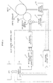
- Fig. 6 is a schematic side view of a printer belt drive control scheme as a first conventional example (as disclosed in Japanese Patent Publication 03-133670).
- the printer belt drive control scheme shown in Fig. 6 includes rotary drums 225a and 225b, a photosensitive belt 221 placed over the rotary drums 225a and 225b, an encoder 223 arranged on a pulley for controlling the feed speed of the photosensitive belt 221; rotary drums 226a and 226b, a paper feed belt 222 placed over the rotary drums 226a and 226b, and an encoder 224 arranged on a pulley for controlling the feed speed of the paper feed belt 222.
- one color printing process includes a cycle of exposure, development, and transfer repeated for the number of colors of the developer and it is very difficult to overlap the color images.
- an eccentricity is present in the rotary drums 225a and 225b feeding the photosensitive belt 221 or in the rotary drums 226 and 226b feeding the paper feed belt 222 or in the pulleys of the encoders 223 and 224, the respective color images are obtained out of the ideal image positions, disabling the correct overlap of the color images.
- an image data write is started by a laser beam oscillation from a laser beam oscillator (not depicted) upon reception of a detection signal of the top of a paper (not depicted) from an image top detection sensor (not depicted), and if it is assumed that the time t 1 required for the paper top to travel from an image top detection position B to a transfer position A is equal to the time t2 required for the write tip of the photosensitive belt 221 to travel from a write position C to the transfer position A, then an image exposed and developed is transferred to the paper, starting from the paper top.
- t 1 x 1 / v 1
- v 1 is a feed speed of the photosensitive belt 221 detected by the encoder 223
- v 2 is a feed speed of the paper feed belt 222 detected by the encoder 224
- x 1 is a feed distance of the photosensitive belt 221 from the write position C to the transfer position A
- x 2 is a feed distance of the paper feed belt 222 from the image top detection position B to the transfer position A.
- the feed speed vl of the photosensitive belt 221 and the feed speed v2 of the paper feed belt 222 are maintained at a constant value by the encoders 223 and 224 and if the feed distance xl of the photosensitive belt 221 and the feed distance x2 of the paper feed belt 222 are maintained at a constant value, the color images at the respective cycles of exposure, development, and transfer are completely matched with one another.
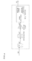
- Fig. 7 is circuit diagram and Fig. 8 is a servo block diagram of a second conventional example.
- a belt motor 6 is provided with only a motor encoder 7 and a belt is controlled by feed back of the motor speed information. There is no consideration on the allowance or rigid components of the gears in a drive transmission mechanism. To obtain a constant rotation of the belt via a drive roller, it has been difficult to constitute a stable belt control system.
- the printer belt drive control circuit includes: an encoder attached to a drive roller for driving a belt to be controlled, and a servo circuit for controlling a rotation speed of a motor for driving the drive roller to be constant according to an output signal from the encoder.
- the printer belt drive control circuit includes: a first encoder attached to a drive roller for driving a belt to be controlled, a second encoder attached to a main shaft of a motor for driving the drive roller, and a servo circuit for controlling a rotation speed of a motor driving the drive roller to be constant according to an output signal from the first encoder and an output signal from the second encoder.
- the printer belt drive control circuit includes: an encoder count circuit (4) for counting output signals from a drive encoder (11) attached to a drive motor (10) and from a motor encoder attached to a belt motor (6), a servo controller which under control of a CPU (1) and outputs a rotation speed information of the belt motor (6) according to tan output signal from the encoder count circuit (4), and a motor drive signal generation circuit for converting an output information from the servo controller (2) into a form appropriate for an H-bridge driver circuit (5) which directly drives the belt motor (6).
- the servo controller includes: an internal ROM contains a program of a control algorithm used for driving a belt (12) and computation equations for control by a software servo method, and an internal register containing servo constants and servo parameters used for a servo computation, which are read out, when necessary, to be substituted in a computation equation.
- the belt drive control circuit (8) is controlled in a closed loop.
- the belt drive control circuit (8) is controlled in a closed loop using software servo control.
- Fig. 1 is a block diagram showing a first embodiment of the present invention.
- Fig. 2 shows an external load configuration around a belt drive block.
- Fig. 3 is a servo block diagram explaining details of the present invention.
- Fig. 4 is a servo block diagram explaining details of the present invention.
- Fig. 5 is a servo block diagram explaining details of the present invention.
- Fig. 6 is a schematic side view of a first conventional example.
- Fig. 7 is a circuit diagram of a second conventional example.
- Fig. 8 is a servo block diagram of the second conventional example.
- Fig. 1 is a block diagram of the embodiment of the present invention.
- a belt drive control circuit 8 includes a servo controller 2, a motor drive signal generation circuit 3, an H-bridge driver circuit 5, and an encoder count circuit 4.
- a color electro-photographic printer belt drive unit includes a belt motor 6, a gear 9 for transmitting a belt motor drive force, a drive roller 10 to which the drive force is transmitted via the gear 9, and a belt 12 rotated by rotation of the drive roller 10.
- the belt motor is provided with a motor encoder 7 and the drive roller 10 is provided with a drive roller encoder for feed back of a speed information of the belts to be controlled.
- the servo controller 2 controls the belt drive control circuit 8 according to the present invention and includes an internal ROM containing a program of the algorithm for controlling to drive the belt.
- the ROM contains computation equations and the like used for controlling by a so-called software servo method.
- the servo controller 2 includes an internal register (not depicted) containing a servo constant and servo parameters used in servo computation performed by the servo controller 2. They are read out from the servo controller 2 when required and substituted into computation equations.
- the motor drive signal generation circuit 3 converts a computation result output from the servo controller 3, into a drive signal to the belt drive motor.
- the H-bridge driver circuit 5 is composed of a driver IC and the like for converting the motor drive signal output from the motor drive signal generation circuit 4, into a motor drive voltage.
- the encoder count circuit 4 computes a speed information of the motor encoder 7 fed back from the belt motor 6 and a speed information of the drive roller encoder 11 fed back from the drive motor 10, and outputs computation results to the servo controller 2.
- the belt drive control circuit 8 constitutes a belt motor control system as a closed loop and controls the belt motor to rotate at a constant speed.
- Fig. 2 shows an external load configuration around a belt drive block in the electro-photographic printer.
- the belt drive block to be controlled according to the present invention has such a configuration that when a print sequence is performed, an external load such as developing rollers 1 to 4 and a transfer roller 107 is brought into a pressed contact with a belt 108.
- the belt 108 is rotated by a drive force for a belt motor (not depicted)d which is transmitted via a gear to a drive roller 100.
- the belt 108 is held by a steering roller for collecting a meander of the belt, a backup roller 106 arranged against the transfer roller via the belt 108, and the like, so that the belt 108 is rotated at a constant speed. Even when the external load round the belt drive block is applied, it is possible to rotate the belt at a constant stable speed by using the color electro-photographic printer belt drive control circuit according to the present invention, whose function will now be explained with reference to Fig. 1.
- a CPU 1 at an upper node to the belt drive control circuit controls the entire print sequence of the electro-photographic printer.
- the CPU 1 upon reception of a print request made by an operator through an operation panel, transmits control instructions to respective units constituting the electro-photographic printer.
- a servo controller 2 receives a motor rotation instruction from the CPU 1.
- the servo controller 2 upon reception of the belt rotation instruction, executes a servo computation equation programmed in advance and outputs a belt rotation speed information to a motor drive signal generation circuit 3.
- the servo controller 2 reads out an optimal servo constant and a servo parameter from an internal register and substitute them in the aforementioned servo computation equation to execute the servo computation equation.
- the motor drive signal generation circuit 3 converts the rotation speed information received from the servo controller 2, into a signal for driving a driver circuit 5 composed of an H-bridge, and outputs the signal.
- the H-bridge driver circuit 5 converts the drive signal into a motor drive voltage and outputs it to a belt motor 6, so that the belt motor 6 starts rotation.
- the drive force of the rotation of the belt motor 6 is transmitted via a gear 9 to a drive roller 10, and the drive roller 10 starts rotation.
- the rotation speed of the drive roller 10 is detected as a speed information by a drive roller encoder 11 and converted into a digital information by an encoder count circuit 4, which is fed back to the servo controller 2.
- the servo controller 2 compares the actual rotation speed information of the drive roller 10 fed back, to a target speed, after which the servo controller 2 again executes the servo computation equation and outputs a rotation speed information to the motor drive signal generation circuit 3.
- the aforementioned control is repeated so that the drive roller 10 is rotated at a constant speed by the belt motor 6, thereby controlling the belt 12 to rotate at a constant speed.
- Fig. 3 is a servo block diagram explaining details of the present invention. This servo block diagram explains the servo control computed by the servo controller shown in Fig. 1.
- a speed instruction (1) for rotating the drive roller at a constant speed and a current speed (6) of the drive roller fed back are supplied to an adder.
- a difference (2) between (1) and (6) is supplied to an integrator.
- An integration result (3) is obtained in the integrator.
- a feed back gain (4) of a drive roller control system is given to the integration result and supplied to a motor feed back control system including the belt motor.
- the belt motor feed back control system has a configuration as shown in Fig. 4.
- the feed back gain (4) of the drive roller is given to the feed back control system, it is supplied to the adder (here, the motor speed feed back is not input and accordingly, not input to a minus side adder) and the output result (4)' is integrated in the integrator to obtain (4)' ', which is then converted into a PWM voltage (4)' ' ' by giving the motor feed back gain.
- the (4) ' ' ' is supplied to the belt motor.
- the belt motor with the PWM voltage, rotates, generating a motor speed.
- the rotation output (5) is transmitted to a gear + drive roller control system.
- the gear + drive roller shown in Fig. 3 receives the rotation output (5) and the gear rotates. Its drive force is transmitted to the drive roller to rotate the drive roller.
- This rotation generates a drive roller speed (6) to rotate the belt connected to the drive roller.
- the drive roller speed (6) is fed back to the drive roller control system and added to the speed instruction (1).
- the aforementioned control is repeated for computation so as to rotate the drive roller at a constant speed.
- control is performed according to a speed information of the encoder attached to the drive roller.
- the printer belt drive control circuit additionally includes a drive roller encoder so as to constitute a stable belt control system considering the gear allowance and rigidity component present in the drive transmission means from a motor to a gear, thereby enabling to rotate a belt at a constant speed.
Landscapes
- Engineering & Computer Science (AREA)
- Microelectronics & Electronic Packaging (AREA)
- Physics & Mathematics (AREA)
- General Physics & Mathematics (AREA)
- Control Of Electric Motors In General (AREA)
- Control Or Security For Electrophotography (AREA)
- Dry Development In Electrophotography (AREA)
- Color Electrophotography (AREA)
- Character Spaces And Line Spaces In Printers (AREA)
Abstract
Description
Claims (6)
- A printer belt drive control circuit comprising:an encoder attached to a drive roller for driving a belt to be controlled, anda servo circuit for controlling a rotation speed of a motor for driving the drive roller to be constant according to an output signal from the encoder.
- A printer belt drive control circuit comprising:a first encoder attached to a drive roller for driving a belt to be controlled,a second encoder attached to a main shaft of a motor for driving the drive roller, anda servo circuit for controlling a rotation speed of a motor driving the drive roller to be constant according to an output signal from the first encoder and an output signal from the second encoder.
- A printer belt drive control circuit comprising:an encoder count circuit for counting output signals from a drive encoder attached to a drive roller and from a motor encoder attached to a belt motor,a servo controller which under control of a CPU and outputs a rotation speed information of the belt motor according to an output signal from the encoder count circuit, anda motor drive signal generation circuit for converting an output information from the servo controller into a form appropriate for an H-bridge driver circuit which directly drives the belt motor.
- A printer belt drive control circuit as claimed in Claim 3, wherein the servo controller includes:an internal ROM containing a program of a control algorithm used for driving a belt and computation equations for control by a software servo method, andan internal register containing servo constants and servo parameters used for a servo computation, which are read out, when necessary, to be substituted in a computation equation.
- A printer belt drive control circuit as claimed in Claim 3 or 4, characterized in that the belt drive control circuit is controlled in a closed loop.
- A printer belt drive control circuit as claimed in Claim 3 or 4, characterized in that the belt drive control circuit is controlled in a closed loop using software servo control.
Applications Claiming Priority (2)
| Application Number | Priority Date | Filing Date | Title |
|---|---|---|---|
| JP2000003425A JP2001194975A (en) | 2000-01-12 | 2000-01-12 | Belt drive control circuit for printer |
| JP2000003425 | 2000-01-12 |
Publications (2)
| Publication Number | Publication Date |
|---|---|
| EP1117011A2 true EP1117011A2 (en) | 2001-07-18 |
| EP1117011A3 EP1117011A3 (en) | 2002-12-04 |
Family
ID=18532373
Family Applications (1)
| Application Number | Title | Priority Date | Filing Date |
|---|---|---|---|
| EP01100107A Withdrawn EP1117011A3 (en) | 2000-01-12 | 2001-01-11 | Printer belt drive control circuit |
Country Status (4)
| Country | Link |
|---|---|
| US (1) | US6538409B2 (en) |
| EP (1) | EP1117011A3 (en) |
| JP (1) | JP2001194975A (en) |
| KR (1) | KR100387155B1 (en) |
Families Citing this family (8)
| Publication number | Priority date | Publication date | Assignee | Title |
|---|---|---|---|---|
| JP4272565B2 (en) * | 2003-07-18 | 2009-06-03 | 株式会社リコー | Belt drive control device and image forming apparatus |
| JP4196902B2 (en) * | 2004-08-23 | 2008-12-17 | ソニー株式会社 | Printing medium traveling apparatus, printing apparatus equipped with the traveling apparatus, printing medium traveling speed control method, and computer program |
| JP4949651B2 (en) * | 2004-10-27 | 2012-06-13 | 株式会社リコー | Belt drive control method, belt drive control device, and image forming apparatus |
| CN100382966C (en) * | 2005-03-15 | 2008-04-23 | 无锡宝南机器制造有限公司 | Servo driving method for folding drawing roller |
| JP4404221B2 (en) * | 2006-09-26 | 2010-01-27 | 株式会社沖データ | Image forming apparatus |
| JP2013219871A (en) * | 2012-04-05 | 2013-10-24 | Canon Inc | Motor control device |
| US10432816B1 (en) * | 2018-08-17 | 2019-10-01 | Hewlett-Packard Development Company, L.P. | Finishing line controllers to optimize the initialization of a printing device |
| WO2023043452A1 (en) * | 2021-09-17 | 2023-03-23 | Hewlett-Packard Development Company, L.P. | Detection of printer motor characteristic |
Family Cites Families (7)
| Publication number | Priority date | Publication date | Assignee | Title |
|---|---|---|---|---|
| US5076568A (en) * | 1990-07-26 | 1991-12-31 | Xerox Corporation | Damping servo-motor control |
| US5325155A (en) | 1993-05-06 | 1994-06-28 | Eastman Kodak Company | Controlling the speed of an image-bearing member using relative states |
| JPH07303385A (en) | 1994-05-09 | 1995-11-14 | Fuji Xerox Co Ltd | Rotary body drive controller |
| US5967445A (en) * | 1996-09-20 | 1999-10-19 | Kabushiki Kaisha Yuyama Seisakusho | Method of adjusting tension applied to sheet, and device for the same |
| JPH10151732A (en) * | 1996-11-21 | 1998-06-09 | Brother Ind Ltd | Inkjet printer |
| US5963706A (en) | 1997-10-23 | 1999-10-05 | Baik; Edward Hyeen | Control system for multi-phase brushless DC motor |
| US6113232A (en) * | 1997-12-19 | 2000-09-05 | Hewlett-Packard Company | Stationary pen printer |
-
2000
- 2000-01-12 JP JP2000003425A patent/JP2001194975A/en active Pending
-
2001
- 2001-01-10 KR KR10-2001-0001415A patent/KR100387155B1/en not_active Expired - Fee Related
- 2001-01-10 US US09/757,933 patent/US6538409B2/en not_active Expired - Fee Related
- 2001-01-11 EP EP01100107A patent/EP1117011A3/en not_active Withdrawn
Also Published As
| Publication number | Publication date |
|---|---|
| JP2001194975A (en) | 2001-07-19 |
| KR20010070493A (en) | 2001-07-25 |
| US6538409B2 (en) | 2003-03-25 |
| KR100387155B1 (en) | 2003-06-12 |
| EP1117011A3 (en) | 2002-12-04 |
| US20010007415A1 (en) | 2001-07-12 |
Similar Documents
| Publication | Publication Date | Title |
|---|---|---|
| CN105071711B (en) | Controller for motor, image forming apparatus and motor control method | |
| US7904000B2 (en) | Image forming apparatus with deceleration measuring section | |
| US10298156B2 (en) | Driving device, drive system, image forming apparatus, conveyance device, and driving method | |
| US6538409B2 (en) | Printer belt drive control circuit | |
| JPH09114348A (en) | Driving controller for image forming device | |
| JP2003021943A (en) | Image forming device | |
| US6933696B2 (en) | Driving device and image forming device | |
| JP3259440B2 (en) | Photoconductor drive control device | |
| JPH10232566A (en) | Image forming device | |
| EP1510875A1 (en) | Colour image forming apparatus with a phase adjusting device | |
| US7962067B2 (en) | Image forming apparatus having phase control of photoconductor groups | |
| JPH09182488A (en) | Drive controller for image formation apparatus | |
| JP4538251B2 (en) | Image forming apparatus | |
| US20020159792A1 (en) | Image forming apparatus | |
| JP2002132008A (en) | Image forming device | |
| JPH08220966A (en) | Drive control device for image forming device | |
| JP2000347535A (en) | Rotary body driving device, image forming device using it and driving method for rotary body | |
| JP4378831B2 (en) | Rotating body driving device, image forming apparatus using the same, and rotating body driving method | |
| JP2002252993A (en) | Motor control method, motor control device, image forming device, image reading device, and recording medium | |
| JP2006023598A (en) | Image forming apparatus | |
| JP3484304B2 (en) | Color image forming apparatus and color image forming method | |
| JPH10119355A (en) | Color image forming equipment | |
| JP4701703B2 (en) | Image forming apparatus and phase adjustment method in the apparatus | |
| JP2006154352A (en) | Rotational speed detection device and image forming apparatus | |
| JPH1152658A (en) | Image forming device |
Legal Events
| Date | Code | Title | Description |
|---|---|---|---|
| PUAI | Public reference made under article 153(3) epc to a published international application that has entered the european phase |
Free format text: ORIGINAL CODE: 0009012 |
|
| AK | Designated contracting states |
Kind code of ref document: A2 Designated state(s): AT BE CH CY DE DK ES FI FR GB GR IE IT LI LU MC NL PT SE TR |
|
| AX | Request for extension of the european patent |
Free format text: AL;LT;LV;MK;RO;SI |
|
| RAP1 | Party data changed (applicant data changed or rights of an application transferred) |
Owner name: FUJI XEROX CO., LTD. |
|
| PUAL | Search report despatched |
Free format text: ORIGINAL CODE: 0009013 |
|
| AK | Designated contracting states |
Kind code of ref document: A3 Designated state(s): AT BE CH CY DE DK ES FI FR GB GR IE IT LI LU MC NL PT SE TR |
|
| AX | Request for extension of the european patent |
Free format text: AL;LT;LV;MK;RO;SI |
|
| 17P | Request for examination filed |
Effective date: 20030604 |
|
| AKX | Designation fees paid |
Designated state(s): DE FR GB |
|
| 17Q | First examination report despatched |
Effective date: 20041026 |
|
| STAA | Information on the status of an ep patent application or granted ep patent |
Free format text: STATUS: THE APPLICATION IS DEEMED TO BE WITHDRAWN |
|
| 18D | Application deemed to be withdrawn |
Effective date: 20050307 |