EP1116961A2 - Method and system for tracking human speakers - Google Patents
Method and system for tracking human speakers Download PDFInfo
- Publication number
- EP1116961A2 EP1116961A2 EP00311706A EP00311706A EP1116961A2 EP 1116961 A2 EP1116961 A2 EP 1116961A2 EP 00311706 A EP00311706 A EP 00311706A EP 00311706 A EP00311706 A EP 00311706A EP 1116961 A2 EP1116961 A2 EP 1116961A2
- Authority
- EP
- European Patent Office
- Prior art keywords
- voice
- speaker
- favorable
- human speaker
- beamformer
- Prior art date
- Legal status (The legal status is an assumption and is not a legal conclusion. Google has not performed a legal analysis and makes no representation as to the accuracy of the status listed.)
- Granted
Links
Images

Classifications
-
- G—PHYSICS
- G01—MEASURING; TESTING
- G01V—GEOPHYSICS; GRAVITATIONAL MEASUREMENTS; DETECTING MASSES OR OBJECTS; TAGS
- G01V1/00—Seismology; Seismic or acoustic prospecting or detecting
- G01V1/001—Acoustic presence detection
-
- G—PHYSICS
- G10—MUSICAL INSTRUMENTS; ACOUSTICS
- G10K—SOUND-PRODUCING DEVICES; METHODS OR DEVICES FOR PROTECTING AGAINST, OR FOR DAMPING, NOISE OR OTHER ACOUSTIC WAVES IN GENERAL; ACOUSTICS NOT OTHERWISE PROVIDED FOR
- G10K11/00—Methods or devices for transmitting, conducting or directing sound in general; Methods or devices for protecting against, or for damping, noise or other acoustic waves in general
- G10K11/18—Methods or devices for transmitting, conducting or directing sound
- G10K11/26—Sound-focusing or directing, e.g. scanning
- G10K11/34—Sound-focusing or directing, e.g. scanning using electrical steering of transducer arrays, e.g. beam steering
-
- H—ELECTRICITY
- H04—ELECTRIC COMMUNICATION TECHNIQUE
- H04R—LOUDSPEAKERS, MICROPHONES, GRAMOPHONE PICK-UPS OR LIKE ACOUSTIC ELECTROMECHANICAL TRANSDUCERS; ELECTRIC HEARING AIDS; PUBLIC ADDRESS SYSTEMS
- H04R3/00—Circuits for transducers
- H04R3/005—Circuits for transducers for combining the signals of two or more microphones
-
- H—ELECTRICITY
- H04—ELECTRIC COMMUNICATION TECHNIQUE
- H04R—LOUDSPEAKERS, MICROPHONES, GRAMOPHONE PICK-UPS OR LIKE ACOUSTIC ELECTROMECHANICAL TRANSDUCERS; ELECTRIC HEARING AIDS; PUBLIC ADDRESS SYSTEMS
- H04R2201/00—Details of transducers, loudspeakers or microphones covered by H04R1/00 but not provided for in any of its subgroups
- H04R2201/40—Details of arrangements for obtaining desired directional characteristic by combining a number of identical transducers covered by H04R1/40 but not provided for in any of its subgroups
- H04R2201/401—2D or 3D arrays of transducers
-
- H—ELECTRICITY
- H04—ELECTRIC COMMUNICATION TECHNIQUE
- H04R—LOUDSPEAKERS, MICROPHONES, GRAMOPHONE PICK-UPS OR LIKE ACOUSTIC ELECTROMECHANICAL TRANSDUCERS; ELECTRIC HEARING AIDS; PUBLIC ADDRESS SYSTEMS
- H04R2201/00—Details of transducers, loudspeakers or microphones covered by H04R1/00 but not provided for in any of its subgroups
- H04R2201/40—Details of arrangements for obtaining desired directional characteristic by combining a number of identical transducers covered by H04R1/40 but not provided for in any of its subgroups
- H04R2201/403—Linear arrays of transducers
Definitions
- the present invention relates generally to a microphone array that tracks the direction of the voice of human speakers and, more specifically, to a hands-free mobile phone.
- Mobile phones are commonly used in a car to provide the car driver a convenient telecommunication means.
- the user can use the phone while in the car without stopping the car or pulling the car over to a parking area.
- using a mobile phone while driving raises a safety issue because the driver must constantly adjust the position of the phone with one hand. This may distract the driver from paying attention to the driving.
- a hands-free car phone system that uses a single microphone and a loudspeaker located at a distance from the driver can be a solution to the above-described problem, regarding the safety issue in driving.
- a hands-free system with several microphones, or a multi-microphone system is able to improve the speech-to-ambient noise ratio and make the speech signal sound more natural without the need of bringing the microphone closer to the user's mouth. This approach does not compromise the comfort and convenience of the user.
- Speech enhancement in a multi-microphone system can be achieved by an analog or digital beamforming technique.
- the digital beamforming technique involves a beamformer that uses a plurality of digital filters to filter the electro-acoustic signals received from a plurality of microphones and the filtered signals are summed.
- the beamformer amplifies the microphone signals responsive to sound arriving from a certain direction and attenuates the signals arriving from other directions.
- the beamformer directs a beam of increased sensitivity towards the source in a selected direction in order to improve the signal-to-noise ratio of the microphone system.
- U.S. Patent No. 4,741,038 discloses a sound location arrangement wherein a plurality of electro-acoustical transducers are used to form a plurality of receiving beams to intercept sound from one or more specified directions.
- at least one of the beams is steerable.
- the steerable beam can be used to scan a plurality of predetermined locations in order to compare the sound from those locations to the sound from a currently selected location.
- the above-described systems are either too complicated or they are not designed to perform in an environment such as the interior of a moving car where the ambient noise levels are high and the human speakers in the car are allowed to move within a broader range. Furthermore, the above-described systems do not distinguish the voice from the near-end human speakers from the voice of the far-end human speakers through the loudspeaker of a hands-free phone system.
- the first aspect of the present invention is to provide a system that uses a plurality of acoustic sensors for tracking at least one human speaker in order to effectively detect the voice from the human speaker, wherein the human speaker and the acoustic sensors are separated by a speaker distance along a speaker direction, and wherein the human speaker is allowed to move relative to the acoustic sensors resulting in a change in the speaker direction within an angular range, and wherein each acoustic sensor produces an electrical signal responsive to the voice of the human speaker.
- the system comprises: a) a beamformer operatively connected to the acoustic sensors to receive the electrical signal, wherein the beamformer is capable of forming N different beams, and each of the beams defines a favorable direction to detect the voice from the human speaker by the acoustic sensors and each different beam is directed in a substantially different direction within the angular range, and wherein the beamformer further outputs for each beam a beam power responsive to the voice detected by the acoustic sensors; and b) a comparator operatively connected to the beamformer for comparing the beam power of each beam in order to determine a most favorable direction to detect the voice of the human speaker, wherein the comparator compares the beam power of each beam periodically so as to determine the most favorable detection direction according to the change in the speaker direction.
- the second aspect of the present invention is to provide a method of tracking at least one human speaker using a plurality of acoustic sensors in order to effectively detect the voice from the human speaker, wherein the human speaker and the acoustic sensors are separated by a speaker distance along a speaker direction, and wherein the human speaker is allowed to move relative to the acoustic sensors resulting in a change in the speaker direction within an angular range, and wherein each acoustic sensor produces an electrical signal responsive to the voice of the speaker.
- the method includes the steps of: a) forming N different beams from the electrical signal such that each beam defines a favorable direction to detect the voice of the human speaker by the acoustic sensors and each different beam is directed in a substantially different direction within the angular range, wherein each beam has a beam power responsive to the electrical signal; and b) periodically comparing the beam power of each beam in order to determine the most favorable direction to detect the voice of the human speaker according to the change of the speaker direction.
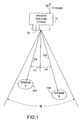
- Figure 1 is a schematic representation of a speaker tracking system showing a plurality of microphones arranged in an array to detect the sounds from two human speakers located at different distances and in different directions.
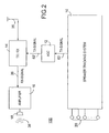
- Figure 2 is a block diagram showing the speaker tracking system being connected to a transceiver to be used as a telecommunication device.
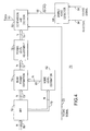
- FIG. 3 is a block diagram showing the components of the speaker tracking system, according to the present invention.
- FIG. 4 is a block diagram showing the detail of the speaker tracking processor of the present invention.
- FIG. 1 shows a speaker tracking system 10 including a plurality of microphones or acoustic sensors 20 arranged in an array for detecting and processing the sounds of human speakers A and B who are located in front of the speaker tracking system 10 .
- This arrangement can be viewed as a hands-free telephone system for use in a car where speaker A represents the driver and speaker B represents a passenger in the back seat.
- the speakers are allowed to move within a certain range.
- the movement range of speaker A is represented by a loop denoted by reference numeral 102 .
- the approximate distance of speaker A from the acoustic sensors 20 is denoted by DA along a general direction denoted by an angle ⁇ A.
- the movement range of speaker B is denoted by reference numeral 104
- the approximate distance of speaker B from the acoustic sensors 20 is denoted by DB along a general direction denoted by an angle ⁇ B.
- the speaker tracking system 10 is used to select a favorable detection direction to track the speaker who speaks.
- the speaker tracking system 10 is designed to form N different beams to cover N different directions within an angular range, ⁇ . Each beam approximately covers an angular range of ⁇ /N.
- the signal responsive to the voice of the speaker as detected in the favorable detection direction is denoted as output signal 62 (Tx-Signal).
- the output signal 62 which can be in a digital or analog form, is conveyed to the transceiver ( Figure 2) so that speakers A and B can communicate with a far-end human speaker at a remote location.
- the acoustic sensors 20 are arranged in a single array substantially along a horizontal line.
- the acoustic sensors 20 can be arranged along a different direction, or in a 2D or 3D array.
- the number of the acoustic sensors 20 is preferably between 4 to 6, when the speaker tracking system 10 is used in a relatively small space such as the interior of a car.
- the number of the acoustic sensors 20 can be smaller or greater, depending on the available installation space and the desired beam resolution.
- the spacing between two adjacent acoustic sensors 20 is about 9cm (3.54").
- the spacing between any two adjacent acoustic sensors can be smaller or larger depending on the number of acoustic sensors in the array.
- the angular range ⁇ is about 120 degrees, but it can be smaller or larger.
- the number N of the beams is 6 to 8, but it can be smaller or larger, depending on the angular coverage of the beams and the desired beam resolution. It should be noted, however, that the coverage angle ⁇ /N for each beam is estimated only from the main lobe of the beam. In practice, the coverage angle of the side-lobes is much larger than ⁇ /N.
- FIG 2 illustrates a telecommunication device 100 , such as a hands-free phone, using the speaker tracking system of the present invention.
- the telecommunication device 100 allows one or more near-end human speakers ( A , B in Figure 1) to communicate with a far-end human speaker (not shown) at a remote location.
- the output signal 62 (Tx-Signal) is conveyed to a transceiver 14 for transmitting to the far-end speaker.
- a gain control device 12 is used to adjust the power level of the output signal 62 .
- the far-end signal 36 (Rx-Signal) received by the transceiver 14 is processed and amplified by an amplifier 16 .
- a loudspeaker 18 is then used to produce sound waves responsive to the processed signal so as to allow the near-end speakers to hear the voice of the far-end speaker in a hands-free fashion.
- FIG. 3 shows the structure of the speaker tracking system 10 .
- each of the acoustic sensors 20 is operatively connected to an A/D converter 30 so that the electro-acoustic signals from the acoustic sensors 20 are conveyed to a beamformer 40 in a digital form.
- the beamformer 40 is used to form N different beams covering N different directions in order to cover the whole area of interest.
- the N signal outputs 50 from the beamformer 40 are conveyed to a speaker tracking processor 70 which compares the N signal outputs 50 to determine the highest signal-to-noise levels among the N signal outputs 50 .
- the speaker tracking processor 70 selects the most favorable direction for receiving the voice of a speaker for a certain time window and sends a signal 90 to a beam power selecting device, such as an overlap-add device 60 .
- the signal 90 includes information indicating a direction of arrival (DOA) which is the most favorable detection direction.
- DOA direction of arrival
- the overlap-add device 60 which also receives the N output signals 50 from the beamformer 40 , selects the output signal according to the DOA sent by the speaker tracking processor 70 .
- the beamformer 40 updates the N output signals 50 with a certain sampling frequency F and sends the N updated output signals 50 to the speaker tracking processor 70 in order to update the DOA.
- the DOA remains the same and there is no need for the overlap-add device 60 to change to a new output signal.
- the speaker tracking processor 70 sends out a new DOA signal 90 to the overlap-add device 60 .
- the overlap-add device selects a new output signal among the N updated output signals 50 .
- an overlap-add procedure is used to join the successive beamformer output segments corresponding to the old beam direction and the new beam direction.
- a voice activity detection device is used to differentiate noise from the voice of the human speakers. With a preset detection level, a voice activity detection device can indicate when a voice is present and when there is only noise.
- a voice-activity detector (Tx-VAD) 32 is used to send a signal 33 to the speaker tracking processor 70 to indicate when any of the human speakers speaks and when it is a noise-only period.
- a voice-activity detector (Rx-VAD) 34 is used to send a signal 35 to the speaker tracking processor 70 to indicate when the voice of the far-end human speaker is detected and when there is no voice but noise from the far-end being detected.
- the voice-activity detector 34 can be implemented near the speaker tracking processor 70 as part of the speaker tracking system 10 , or it can be implemented at the transmitter end of the far-end human speakers for sending information related to the signal 35 to the speaker tracking processor 70 .
- a signal 36 responsive to the sound from the far-end human speaker is conveyed to the speaker tracking processor 70 for babble noise estimation, as described in conjunction with Figure 4 below.
- the update frequency F for direction estimation is between 8Hz to 50Hz, but it can be higher or lower.
- the DOA as indicated by signal 90 generally represents a favorable detection direction within a time window defined by 1/F, which ranges from 20ms to 125ms.
- the speaker tracking system 10 is allowed to operate in at least two different modes:
- a MODE control device 38 is used to send a MODE signal 39 to the speaker tracking processor 70 .
- the overlap-add procedure for directional smoothing is carried out as follows.
- the overlapping frames of the output of the beamformer 40 are windowed by a trapezoidal window and the overlapping windowed frames are added together.
- the slope of the window must be long enough to smooth the effect arising from the changing of beam directions.
- the Tx-Signal 62 represents the beam power of a selected beam within a sampling window as smoothed by the overlap-add device 60 .
- a typical overlap time is about 50ms.
- FIG 4 illustrates the direction estimation process carried out by the speaker tracking processor 70 of the present invention.
- each of the N output signals 50 is filtered by a band-pass filter (BPF) 72 in order to optimize the speech-to-ambient noise ratio and the beamformer directivity.
- the band-pass filter frequency is about 1kHz to 2kHz.
- the band-pass filtered signals 73 are simultaneously conveyed to a noise-level estimation device 82 and a beam-power estimation device 74.
- a Tx-VAD signal 33 provided by the voice-activity detector 32 ( Figure 3) is conveyed to both the noise-level estimation device 82 and a comparison and decision device 80 .
- the noise-level estimation device 82 estimates the noise power level of each beam.
- FLEN is the frame length used for noise estimation.
- the estimated noise power level 83 for each of the N beams is conveyed to the beam-power estimation device 74 .
- Each power level is normalized with the noise level of the corresponding beam. This normalization process helps bring out only the power differences in the voice in different beam directions. It also helps reduce the differences in the power level due to the possible differences in the beam-width.
- the sound level from speaker B as detected by the acoustic sensors is generally lower. It is possible that a different weighting factor is given to the signals responsive to the sound of different speakers in order to increase the level of a weaker sound. For example, a weighting factor of 1 can be given to the beams that are directed towards the general direction of speaker B , while a weighting factor of 0.8 can be given to the beams that are directed towards the general direction of speaker A . However, if it is desirable to design a speaker tracking system that favors the driver, then a larger weighting factor can be given to the beams that are directed towards to the general direction of the driver.
- the adjusted power levels 79 are conveyed to a comparison and decision device 80 .
- the normalization device 76 and the power level adjuster 78 are omitted so that the estimated power levels from the beam-power estimation device 74 are directly conveyed to the comparison and decision device 80 . Based on the power levels received, the comparison and decision device 80 select the highest power.
- the voice of the far-end speaker is reproduced on a loudspeaker of a hands-free telecommunication device ( Figure 2).
- the voice of the far-end speaker on the loudspeaker may confuse the comparison and decision device 80 as to which should be used for the selection of the DOA.
- the power level of the currently selected direction is compared to those of the other directions. If one of the other directions has a clearly higher level, such as the difference is over 2dBs, for example, that direction is chosen as the new DOA.
- the major advantage of the VADs is that the speaker tracking system 10 only reacts to true near-end speech and not some noise-related impulses, or the voice of the far-end speaker from the loudspeaker of the hands-free phone system.
- the electro-acoustic signals from the acoustic sensors 20 are conveyed to the beamformer 40 in a digital form. Accordingly, a filter-and-sum beamforming technique is used for beamforming. However, the electro-acoustic signals from the acoustic sensors 20 can also be conveyed to the beamformer 40 in an analog form. Accordingly, a delay-and-sum technique can be used for beamforming.
- the acoustic sensors 20 can be arranged in a 2D array or a 3D array in different arrangements. It is understood that the beamforming process using a single array can only steer a beam in one direction, the beamforming process using a 2D array can steer the beam in two directions. With a 3D acoustic sensor array, the distance of the speaker can also be determined, in addition to the directions. In spite of the complexity of a system the uses a 2D or 3D acoustic sensor array, the principle of speaker tracking remains the same.
Landscapes
- Physics & Mathematics (AREA)
- Acoustics & Sound (AREA)
- Engineering & Computer Science (AREA)
- Life Sciences & Earth Sciences (AREA)
- Environmental & Geological Engineering (AREA)
- General Life Sciences & Earth Sciences (AREA)
- Signal Processing (AREA)
- General Health & Medical Sciences (AREA)
- Health & Medical Sciences (AREA)
- Geology (AREA)
- Remote Sensing (AREA)
- Otolaryngology (AREA)
- General Physics & Mathematics (AREA)
- Geophysics (AREA)
- Multimedia (AREA)
- Circuit For Audible Band Transducer (AREA)
- Telephone Set Structure (AREA)
- Telephone Function (AREA)
- Measurement Of Velocity Or Position Using Acoustic Or Ultrasonic Waves (AREA)
Abstract
Description
Claims (24)
- A system having a plurality of acoustic sensors for tracking at least one human speaker in order to effectively detect a voice from the human speaker, wherein the human speaker and the acoustic sensors are separated by a speaker distance along a speaker direction and wherein the human speaker is allowed to move relative to the acoustic sensors resulting in a change in the speaker direction within an angular range, and wherein each acoustic sensor produces an electrical signal responsive to the voice of the human speaker, said system comprising:a) a beamformer operatively connected to the acoustic sensors to receive the electrical signal, wherein the beamformer is capable of forming N different beams, wherein N is a positive integer greater than 1 and each beam defining a favorable direction to detect the voice from the human speaker by the acoustic sensors and each different beam is directed in a substantially different direction within the angular range, said beamformer further outputting an output signal representative of a beam power for each beam when the acoustic sensors detect the voice; andb) a comparator operatively connected to said beamformer for comparing the beam power of each beam in order to determine a most favorable direction to detect the voice of the human speaker, wherein said comparator compares the beam power of each beam periodically so as to determine the most favorable direction to detect the voice of the human speaker according to the change in the speaker direction.
- The system of claim 1, further comprising a voice activity detection device to define a near-end speech activity period when the voice from the human speaker is detected during a detection period, wherein the comparator determines the most favorable detection direction only in the near-end speech activity period.
- The system of claim 2, wherein the voice activity detection device further defines a near-end speech inactivity period when the voice of the human speaker using the system is not detected in the detection period, said system further comprising a power estimation device and a noise level estimation device operatively connected to the beamformer to receive the beam power of each beam, wherein the noise level estimation device estimates an ambient noise in the near-end speech inactivity period and wherein the power estimation device estimates the beam power of each beam based on the ambient noise and provides the estimated beam power to the comparator in order for the comparator to determine the most favorable detection direction.
- The system of claim 3, further comprising a band-pass filter to filter the output signal from the beamformer prior to the beam power of each beam from the beamformer being conveyed to the power estimation device and the noise level estimation device.
- The system of claim 1, further comprising a transceiver to transmit the voice of the human speaker utilizing the system to communicate with a far-end human speaker in a communication period and to receive a far-end voice signal responsive to a voice from the far-end human speaker during the communication period.
- The system of claim 5, further comprising a voice activity detection device to indicate a far-end speech inactivity period, wherein the comparator determines the most favorable detection direction only in the far-end speech inactivity period.
- The system of claim 6, further comprising a babble noise detector for receiving the far-end voice signal and a signal from the voice activity detection device in order to generate a far-end speech inactivity signal conveyed to the comparator for indicating the far-end speech inactivity period.
- The system of claim 1, wherein the comparator compares the beam power of each beam within a predetermined time period in order to determine the most favorable detection direction and wherein the most favorable detection direction determined within the predetermined time period is kept unchanged after the predetermined time period has expired.
- A method of tracking at least one human speaker using a plurality of acoustic sensors in order to effectively detect a voice from the human speaker, wherein the human speaker and the acoustic sensors are separated by a speaker distance along a speaker direction and wherein the human speaker is allowed to move relative to the acoustic sensors resulting in a change in the speaker direction within an angular range, and wherein each acoustic sensor produces an electrical signal responsive to the voice of the human speaker, said method comprising the steps of:a) forming N different beams from the electrical signal, wherein N is a positive integer greater than 1 and each beam defining a favorable direction to detect the voice of the human speaker by the acoustic sensors and each different beam is directed in a substantially different direction within the angular range, wherein each beam has a beam power responsive to the electrical signal; andb) periodically comparing the beam power of each beam in order to determine a most favorable direction to detect the voice of the human speaker according to the change of the speaker direction.
- The method of claim 9, further comprising the step of determining a near-end speech activity period when the voice of the human speaker is detected in a detection period so that the beam power of each beam in the detection period is compared to determine the most favorable detection direction only in the near-end speech activity period.
- The method of claim 10, further comprising the steps of:determining a near-end speech inactivity period when the voice of the human speaker is not detected in the detection period;estimating an ambient noise during the near-end speech inactivity period; andestimating the beam power of each beam based on the ambient noise so as to use the estimated beam power of each beam to determine the most favorable detection direction.
- The method of claim 9, wherein the human speaker communicates with a far-end human speaker at a remote location in a communication period, said method further comprising the step of receiving a voice of the far-end human speaker and indicating a far-end speech inactivity period so that the beam power of each beam is compared to determine the most favorable detection direction only in the far-end speech inactivity period.
- The method of claim 9, wherein each beam has a beamformer output related to the power of said beam, the method further comprising the step of frequency filtering the beamformer output of each beam prior to determining the most favorable detection direction in step 2.
- The method of claim 13, wherein the beamformer output is filtered by a band-pass filter having a frequency range of 1kHz and 2kHz.
- The method of claim 13, wherein the most favorable detection direction is updated with a frequency ranging from 8Hz to 50Hz in order to obtain a new most favorable detection direction for replacing a current most favorable detection direction, said method further comprising the step of adding a part of the beamformer output of the current most favorable detection direction to a part of the beamformer output of the new most favorable detection direction in order to smooth out the beamformer output difference between the new and the current most favorable detection direction.
- The method of claim 9, wherein the beam power comparing step is carried out within a predetermined time period and wherein the most favorable direction so determined is kept unchanged after the predetermined time period has expired.
- The method of claim 9, wherein the acoustic sensors are arranged in a single array.
- The method of claim 9, wherein the acoustic sensors are arranged in a 2D array.
- The method of claim 9, wherein the acoustic sensors are arranged in a 3D array.
- The method of claim 9, wherein the most favorable detection direction is updated with a frequency ranging from 8Hz to 50Hz in order to obtain a new most favorable detection direction for replacing a current most favorable detection direction.
- The method of claim 20, wherein the current most favorable detection direction is replaced by the new most favorable detection direction only when the beam power difference between the new and the current most favorable detection direction exceeds 2dBs.
- The method of claim 9, further comprising the step of assigning a weighting factor to each beam according to the speaker direction in order to adjust the beam power of each beam prior to determining the most favorable detection direction in step 2.
- The method of claim 9, further comprising the step of assigning a weighting factor to each beam according to the speaker location in order to adjust the beam power of each beam prior to determining the most favorable detection direction in step 2.
- A system having a plurality of acoustic sensors (20) for detecting and tracking the voice of a human speaker that can move relative to the sensors so as to be separated by a speaker distance along a speaker direction and within an angular range, and wherein each acoustic sensor produces an electrical signal responsive to the voice of the human speaker, characterised bya beamformer (40) operatively connected to the acoustic sensors to receive the electrical signal, wherein the beamformer is capable of forming N different beams, wherein N is a positive integer greater than 1 and each beam defining a favorable direction to detect the voice from the human speaker by the acoustic sensors and each different beam is directed in a substantially different direction within the angular range, said beamformer further outputting an output signal (75) representative of a beam power for each beam when the acoustic sensors detect the voice; anda comparator (80) operatively connected to said beamformer for comparing the beam power of each beam in order to determine a most favorable direction to detect the voice of the human speaker.
Applications Claiming Priority (2)
| Application Number | Priority Date | Filing Date | Title |
|---|---|---|---|
| US09/482,825 US6449593B1 (en) | 2000-01-13 | 2000-01-13 | Method and system for tracking human speakers |
| US482825 | 2000-01-13 |
Publications (3)
| Publication Number | Publication Date |
|---|---|
| EP1116961A2 true EP1116961A2 (en) | 2001-07-18 |
| EP1116961A3 EP1116961A3 (en) | 2002-03-13 |
| EP1116961B1 EP1116961B1 (en) | 2005-08-31 |
Family
ID=23917606
Family Applications (1)
| Application Number | Title | Priority Date | Filing Date |
|---|---|---|---|
| EP00311706A Expired - Lifetime EP1116961B1 (en) | 2000-01-13 | 2000-12-27 | Method and system for tracking human speakers |
Country Status (4)
| Country | Link |
|---|---|
| US (1) | US6449593B1 (en) |
| EP (1) | EP1116961B1 (en) |
| JP (1) | JP4694700B2 (en) |
| DE (1) | DE60022304T2 (en) |
Cited By (20)
| Publication number | Priority date | Publication date | Assignee | Title |
|---|---|---|---|---|
| WO2003073786A1 (en) * | 2002-02-27 | 2003-09-04 | Shure Incorporated | Multiple beam microphone array having automatic mixing processing via speech detection |
| EP1475997A3 (en) * | 2003-05-09 | 2004-12-22 | Harman/Becker Automotive Systems GmbH | Method and system for communication enhancement in a noisy environment |
| WO2007004188A3 (en) * | 2005-07-06 | 2007-05-03 | Koninkl Philips Electronics Nv | Apparatus and method for acoustic beamforming |
| WO2007122749A1 (en) * | 2006-04-21 | 2007-11-01 | Yamaha Corporation | Sound pickup device and voice conference apparatus |
| WO2007125449A1 (en) * | 2006-04-28 | 2007-11-08 | Koninklijke Philips Electronics N.V. | Device for and method of estimating directivity of a microphone arrangement |
| EP1571875A3 (en) * | 2004-03-02 | 2009-01-28 | Microsoft Corporation | A system and method for beamforming using a microphone array |
| US7643641B2 (en) | 2003-05-09 | 2010-01-05 | Nuance Communications, Inc. | System for communication enhancement in a noisy environment |
| EP2404453A4 (en) * | 2009-04-16 | 2013-05-01 | Nokia Corp | APPARATUS, METHODS AND COMPUTER PROGRAM PRODUCTS FOR CONVERTING SOUND WAVES IN ELECTRICAL SIGNALS |
| US8724822B2 (en) | 2003-05-09 | 2014-05-13 | Nuance Communications, Inc. | Noisy environment communication enhancement system |
| WO2016028448A1 (en) * | 2014-08-19 | 2016-02-25 | Apple Inc. | Method and apparatus for estimating talker distance |
| WO2016093855A1 (en) * | 2014-12-12 | 2016-06-16 | Nuance Communications, Inc. | System and method for generating a self-steering beamformer |
| US9502050B2 (en) | 2012-06-10 | 2016-11-22 | Nuance Communications, Inc. | Noise dependent signal processing for in-car communication systems with multiple acoustic zones |
| EP3116235A1 (en) * | 2015-07-10 | 2017-01-11 | Samsung Electronics Co., Ltd. | Electronic device and input/output method thereof |
| US9613633B2 (en) | 2012-10-30 | 2017-04-04 | Nuance Communications, Inc. | Speech enhancement |
| US9805738B2 (en) | 2012-09-04 | 2017-10-31 | Nuance Communications, Inc. | Formant dependent speech signal enhancement |
| DE102016013042A1 (en) * | 2016-11-02 | 2018-05-03 | Audi Ag | Microphone system for a motor vehicle with dynamic directional characteristics |
| EP3337189A1 (en) * | 2016-12-15 | 2018-06-20 | Sivantos Pte. Ltd. | Method for determining a position of a signal source |
| EP3416407A1 (en) * | 2017-06-13 | 2018-12-19 | Nxp B.V. | Signal processor |
| WO2022022139A1 (en) * | 2020-07-27 | 2022-02-03 | 腾讯科技(深圳)有限公司 | Voice detection method based on multiple sound regions, related device, and storage medium |
| EP3811633A4 (en) * | 2018-06-25 | 2022-03-23 | Biamp Systems, LLC | MICROPHONE ARRANGEMENT WITH AUTOMATED ADAPTIVE BEAM TRACKING |
Families Citing this family (89)
| Publication number | Priority date | Publication date | Assignee | Title |
|---|---|---|---|---|
| JP2001075594A (en) * | 1999-08-31 | 2001-03-23 | Pioneer Electronic Corp | Speech recognition system |
| US20020031234A1 (en) * | 2000-06-28 | 2002-03-14 | Wenger Matthew P. | Microphone system for in-car audio pickup |
| GB2364121B (en) * | 2000-06-30 | 2004-11-24 | Mitel Corp | Method and apparatus for locating a talker |
| EP1184676B1 (en) * | 2000-09-02 | 2004-05-06 | Nokia Corporation | System and method for processing a signal being emitted from a target signal source into a noisy environment |
| GB2367730B (en) * | 2000-10-06 | 2005-04-27 | Mitel Corp | Method and apparatus for minimizing far-end speech effects in hands-free telephony systems using acoustic beamforming |
| US6529608B2 (en) * | 2001-01-26 | 2003-03-04 | Ford Global Technologies, Inc. | Speech recognition system |
| GB2379148A (en) * | 2001-08-21 | 2003-02-26 | Mitel Knowledge Corp | Voice activity detection |
| GB0121206D0 (en) * | 2001-08-31 | 2001-10-24 | Mitel Knowledge Corp | System and method of indicating and controlling sound pickup direction and location in a teleconferencing system |
| US20030050777A1 (en) * | 2001-09-07 | 2003-03-13 | Walker William Donald | System and method for automatic transcription of conversations |
| US6937980B2 (en) * | 2001-10-02 | 2005-08-30 | Telefonaktiebolaget Lm Ericsson (Publ) | Speech recognition using microphone antenna array |
| GB2388001A (en) * | 2002-04-26 | 2003-10-29 | Mitel Knowledge Corp | Compensating for beamformer steering delay during handsfree speech recognition |
| WO2003105124A1 (en) * | 2002-06-11 | 2003-12-18 | Sony Electronics Inc. | Microphone array with time-frequency source discrimination |
| US7224981B2 (en) * | 2002-06-20 | 2007-05-29 | Intel Corporation | Speech recognition of mobile devices |
| GB0317158D0 (en) * | 2003-07-23 | 2003-08-27 | Mitel Networks Corp | A method to reduce acoustic coupling in audio conferencing systems |
| KR20060113714A (en) * | 2003-11-24 | 2006-11-02 | 코닌클리케 필립스 일렉트로닉스 엔.브이. | Adaptive Beamformer Immunity to Uncorrelated Noise |
| US7778425B2 (en) * | 2003-12-24 | 2010-08-17 | Nokia Corporation | Method for generating noise references for generalized sidelobe canceling |
| WO2005065012A2 (en) * | 2003-12-24 | 2005-07-21 | Nokia Corporation | A method for efficient beamforming using a complementary noise separation filter |
| US20050147258A1 (en) * | 2003-12-24 | 2005-07-07 | Ville Myllyla | Method for adjusting adaptation control of adaptive interference canceller |
| US8275147B2 (en) * | 2004-05-05 | 2012-09-25 | Deka Products Limited Partnership | Selective shaping of communication signals |
| KR100586893B1 (en) * | 2004-06-28 | 2006-06-08 | 삼성전자주식회사 | Speaker Location Estimation System and Method in Time-Varying Noise Environment |
| US7475014B2 (en) * | 2005-07-25 | 2009-01-06 | Mitsubishi Electric Research Laboratories, Inc. | Method and system for tracking signal sources with wrapped-phase hidden markov models |
| JP4675381B2 (en) * | 2005-07-26 | 2011-04-20 | 本田技研工業株式会社 | Sound source characteristic estimation device |
| US7689248B2 (en) * | 2005-09-27 | 2010-03-30 | Nokia Corporation | Listening assistance function in phone terminals |
| US7706549B2 (en) * | 2006-09-14 | 2010-04-27 | Fortemedia, Inc. | Broadside small array microphone beamforming apparatus |
| US20080146289A1 (en) * | 2006-12-14 | 2008-06-19 | Motorola, Inc. | Automatic audio transducer adjustments based upon orientation of a mobile communication device |
| WO2008106036A2 (en) | 2007-02-26 | 2008-09-04 | Dolby Laboratories Licensing Corporation | Speech enhancement in entertainment audio |
| JP4897519B2 (en) * | 2007-03-05 | 2012-03-14 | 株式会社神戸製鋼所 | Sound source separation device, sound source separation program, and sound source separation method |
| EP1983799B1 (en) * | 2007-04-17 | 2010-07-07 | Harman Becker Automotive Systems GmbH | Acoustic localization of a speaker |
| US8244528B2 (en) * | 2008-04-25 | 2012-08-14 | Nokia Corporation | Method and apparatus for voice activity determination |
| US8611556B2 (en) * | 2008-04-25 | 2013-12-17 | Nokia Corporation | Calibrating multiple microphones |
| US8275136B2 (en) * | 2008-04-25 | 2012-09-25 | Nokia Corporation | Electronic device speech enhancement |
| WO2009145192A1 (en) * | 2008-05-28 | 2009-12-03 | 日本電気株式会社 | Voice detection device, voice detection method, voice detection program, and recording medium |
| DE102008064484B4 (en) * | 2008-12-22 | 2012-01-19 | Siemens Medical Instruments Pte. Ltd. | Method for selecting a preferred direction of a directional microphone and corresponding hearing device |
| JP2011090408A (en) * | 2009-10-20 | 2011-05-06 | Canon Inc | Information processor, and action estimation method and program of the same |
| WO2011055410A1 (en) * | 2009-11-06 | 2011-05-12 | 株式会社 東芝 | Voice recognition device |
| TWI396862B (en) * | 2009-12-04 | 2013-05-21 | Teco Elec & Machinery Co Ltd | Method, computer readable storage medium and system for localizing acoustic source |
| WO2011073735A1 (en) * | 2009-12-18 | 2011-06-23 | Telefonaktiebolaget L M Ericsson (Publ) | Activity actuated speech enhancement in multi-microphone teleconference systems |
| KR101750338B1 (en) * | 2010-09-13 | 2017-06-23 | 삼성전자주식회사 | Method and apparatus for microphone Beamforming |
| JP5872163B2 (en) | 2011-01-07 | 2016-03-01 | オムロン株式会社 | Acoustic transducer and microphone using the acoustic transducer |
| US9380380B2 (en) | 2011-01-07 | 2016-06-28 | Stmicroelectronics S.R.L. | Acoustic transducer and interface circuit |
| JP5273162B2 (en) * | 2011-01-11 | 2013-08-28 | ヤマハ株式会社 | Sound collector |
| US9264553B2 (en) * | 2011-06-11 | 2016-02-16 | Clearone Communications, Inc. | Methods and apparatuses for echo cancelation with beamforming microphone arrays |
| US9232310B2 (en) * | 2012-10-15 | 2016-01-05 | Nokia Technologies Oy | Methods, apparatuses and computer program products for facilitating directional audio capture with multiple microphones |
| CN104010265A (en) * | 2013-02-22 | 2014-08-27 | 杜比实验室特许公司 | Audio space rendering device and method |
| US9232072B2 (en) | 2013-03-13 | 2016-01-05 | Google Inc. | Participant controlled spatial AEC |
| US9813808B1 (en) * | 2013-03-14 | 2017-11-07 | Amazon Technologies, Inc. | Adaptive directional audio enhancement and selection |
| US9847082B2 (en) * | 2013-08-23 | 2017-12-19 | Honeywell International Inc. | System for modifying speech recognition and beamforming using a depth image |
| KR101491354B1 (en) * | 2013-11-25 | 2015-02-06 | 현대자동차주식회사 | Apparatus and Method for Recognize of Voice |
| KR102177553B1 (en) * | 2014-03-27 | 2020-11-11 | 삼성전자주식회사 | Method and apparatus for beamforming to serving multiple user |
| US9716946B2 (en) | 2014-06-01 | 2017-07-25 | Insoundz Ltd. | System and method thereof for determining of an optimal deployment of microphones to achieve optimal coverage in a three-dimensional space |
| US9930462B2 (en) | 2014-09-14 | 2018-03-27 | Insoundz Ltd. | System and method for on-site microphone calibration |
| US20160150315A1 (en) * | 2014-11-20 | 2016-05-26 | GM Global Technology Operations LLC | System and method for echo cancellation |
| CN107004426B (en) * | 2014-11-28 | 2020-09-11 | 华为技术有限公司 | Method and mobile terminal for recording voice of video recording object |
| US9554207B2 (en) | 2015-04-30 | 2017-01-24 | Shure Acquisition Holdings, Inc. | Offset cartridge microphones |
| US9565493B2 (en) | 2015-04-30 | 2017-02-07 | Shure Acquisition Holdings, Inc. | Array microphone system and method of assembling the same |
| DE102015210652B4 (en) | 2015-06-10 | 2019-08-08 | Sivantos Pte. Ltd. | Method for improving a recording signal in a hearing system |
| US10849205B2 (en) | 2015-10-14 | 2020-11-24 | Current Lighting Solutions, Llc | Luminaire having a beacon and a directional antenna |
| US10367948B2 (en) | 2017-01-13 | 2019-07-30 | Shure Acquisition Holdings, Inc. | Post-mixing acoustic echo cancellation systems and methods |
| US11133036B2 (en) | 2017-03-13 | 2021-09-28 | Insoundz Ltd. | System and method for associating audio feeds to corresponding video feeds |
| JP6686977B2 (en) * | 2017-06-23 | 2020-04-22 | カシオ計算機株式会社 | Sound source separation information detection device, robot, sound source separation information detection method and program |
| US11317232B2 (en) | 2017-10-17 | 2022-04-26 | Hewlett-Packard Development Company, L.P. | Eliminating spatial collisions due to estimated directions of arrival of speech |
| CN109859749A (en) | 2017-11-30 | 2019-06-07 | 阿里巴巴集团控股有限公司 | A kind of voice signal recognition method and device |
| US11172319B2 (en) | 2017-12-21 | 2021-11-09 | Insoundz Ltd. | System and method for volumetric sound generation |
| CN112335261B (en) | 2018-06-01 | 2023-07-18 | 舒尔获得控股公司 | patterned microphone array |
| US11297423B2 (en) | 2018-06-15 | 2022-04-05 | Shure Acquisition Holdings, Inc. | Endfire linear array microphone |
| US11310596B2 (en) | 2018-09-20 | 2022-04-19 | Shure Acquisition Holdings, Inc. | Adjustable lobe shape for array microphones |
| US11303981B2 (en) | 2019-03-21 | 2022-04-12 | Shure Acquisition Holdings, Inc. | Housings and associated design features for ceiling array microphones |
| US11558693B2 (en) | 2019-03-21 | 2023-01-17 | Shure Acquisition Holdings, Inc. | Auto focus, auto focus within regions, and auto placement of beamformed microphone lobes with inhibition and voice activity detection functionality |
| JP7572964B2 (en) | 2019-03-21 | 2024-10-24 | シュアー アクイジッション ホールディングス インコーポレイテッド | Beamforming with rejection Autofocus, autofocus in area, and autoplacement of microphone lobes |
| TW202101422A (en) | 2019-05-23 | 2021-01-01 | 美商舒爾獲得控股公司 | Steerable speaker array, system, and method for the same |
| WO2020243471A1 (en) | 2019-05-31 | 2020-12-03 | Shure Acquisition Holdings, Inc. | Low latency automixer integrated with voice and noise activity detection |
| CN114467312A (en) | 2019-08-23 | 2022-05-10 | 舒尔获得控股公司 | Two-dimensional microphone array with improved directivity |
| US12028678B2 (en) | 2019-11-01 | 2024-07-02 | Shure Acquisition Holdings, Inc. | Proximity microphone |
| US11552611B2 (en) | 2020-02-07 | 2023-01-10 | Shure Acquisition Holdings, Inc. | System and method for automatic adjustment of reference gain |
| USD944776S1 (en) | 2020-05-05 | 2022-03-01 | Shure Acquisition Holdings, Inc. | Audio device |
| US11706562B2 (en) | 2020-05-29 | 2023-07-18 | Shure Acquisition Holdings, Inc. | Transducer steering and configuration systems and methods using a local positioning system |
| EP4207196B1 (en) * | 2020-11-11 | 2025-10-29 | Audio-Technica Corporation | Sound collection system, sound collection method, and program |
| JP7814400B2 (en) | 2021-01-28 | 2026-02-16 | シュアー アクイジッション ホールディングス インコーポレイテッド | Hybrid Audio Beamforming System |
| US12452584B2 (en) | 2021-01-29 | 2025-10-21 | Shure Acquisition Holdings, Inc. | Scalable conferencing systems and methods |
| US12542123B2 (en) | 2021-08-31 | 2026-02-03 | Shure Acquisition Holdings, Inc. | Mask non-linear processor for acoustic echo cancellation |
| US12289584B2 (en) | 2021-10-04 | 2025-04-29 | Shure Acquisition Holdings, Inc. | Networked automixer systems and methods |
| US11741982B2 (en) * | 2021-10-05 | 2023-08-29 | Dell Products L.P. | Contextual beamforming to improve signal-to-noise ratio sensitive audio input processing efficiency in noisy environments |
| EP4427465A1 (en) | 2021-11-05 | 2024-09-11 | Shure Acquisition Holdings, Inc. | Distributed algorithm for automixing speech over wireless networks |
| CN114267335B (en) * | 2021-11-29 | 2025-04-08 | 苏州君林智能科技有限公司 | Voice acquisition method and system for multi-factor acquisition room |
| KR20230094005A (en) * | 2021-12-20 | 2023-06-27 | 삼성전자주식회사 | Apparatus and method for classifying a speaker using acoustic sensor |
| EP4202922A1 (en) * | 2021-12-23 | 2023-06-28 | GN Audio A/S | Audio device and method for speaker extraction |
| US12250526B2 (en) | 2022-01-07 | 2025-03-11 | Shure Acquisition Holdings, Inc. | Audio beamforming with nulling control system and methods |
| US12598261B2 (en) | 2022-09-28 | 2026-04-07 | Shure Acquisition Holdings, Inc. | Wideband doubletalk detection for optimization of acoustic echo cancellation |
| US20260046558A1 (en) * | 2024-08-12 | 2026-02-12 | Cisco Technology, Inc. | Gain control of beams of microphone array and external microphone in a videoconference |
Family Cites Families (11)
| Publication number | Priority date | Publication date | Assignee | Title |
|---|---|---|---|---|
| US4741038A (en) * | 1986-09-26 | 1988-04-26 | American Telephone And Telegraph Company, At&T Bell Laboratories | Sound location arrangement |
| GB2202942B (en) * | 1987-03-21 | 1991-08-21 | Ferranti Plc | Production of directionally limited acoustic power spectra |
| US5335011A (en) * | 1993-01-12 | 1994-08-02 | Bell Communications Research, Inc. | Sound localization system for teleconferencing using self-steering microphone arrays |
| US5737430A (en) * | 1993-07-22 | 1998-04-07 | Cardinal Sound Labs, Inc. | Directional hearing aid |
| JPH08335977A (en) * | 1995-06-06 | 1996-12-17 | Kobe Steel Ltd | Loudspeaking device |
| JP3518579B2 (en) * | 1997-06-23 | 2004-04-12 | 日本電信電話株式会社 | Speaker-following room loudspeaker and voice input method |
| JP3541339B2 (en) * | 1997-06-26 | 2004-07-07 | 富士通株式会社 | Microphone array device |
| JP3302300B2 (en) * | 1997-07-18 | 2002-07-15 | 株式会社東芝 | Signal processing device and signal processing method |
| JP3677143B2 (en) * | 1997-07-31 | 2005-07-27 | 株式会社東芝 | Audio processing method and apparatus |
| FI114422B (en) | 1997-09-04 | 2004-10-15 | Nokia Corp | Source speech activity detection |
| JP2000224685A (en) * | 1999-02-03 | 2000-08-11 | Aiwa Co Ltd | Microphone unit |
-
2000
- 2000-01-13 US US09/482,825 patent/US6449593B1/en not_active Expired - Lifetime
- 2000-12-27 DE DE60022304T patent/DE60022304T2/en not_active Expired - Lifetime
- 2000-12-27 EP EP00311706A patent/EP1116961B1/en not_active Expired - Lifetime
-
2001
- 2001-01-10 JP JP2001002788A patent/JP4694700B2/en not_active Expired - Lifetime
Cited By (35)
| Publication number | Priority date | Publication date | Assignee | Title |
|---|---|---|---|---|
| WO2003073786A1 (en) * | 2002-02-27 | 2003-09-04 | Shure Incorporated | Multiple beam microphone array having automatic mixing processing via speech detection |
| US7643641B2 (en) | 2003-05-09 | 2010-01-05 | Nuance Communications, Inc. | System for communication enhancement in a noisy environment |
| EP1475997A3 (en) * | 2003-05-09 | 2004-12-22 | Harman/Becker Automotive Systems GmbH | Method and system for communication enhancement in a noisy environment |
| WO2004100602A3 (en) * | 2003-05-09 | 2005-01-06 | Harman Becker Automotive Sys | Method and system for communication enhancement ina noisy environment |
| US8724822B2 (en) | 2003-05-09 | 2014-05-13 | Nuance Communications, Inc. | Noisy environment communication enhancement system |
| US9002028B2 (en) | 2003-05-09 | 2015-04-07 | Nuance Communications, Inc. | Noisy environment communication enhancement system |
| EP1571875A3 (en) * | 2004-03-02 | 2009-01-28 | Microsoft Corporation | A system and method for beamforming using a microphone array |
| WO2007004188A3 (en) * | 2005-07-06 | 2007-05-03 | Koninkl Philips Electronics Nv | Apparatus and method for acoustic beamforming |
| CN101218848B (en) * | 2005-07-06 | 2011-11-16 | 皇家飞利浦电子股份有限公司 | Apparatus and method for acoustic beamforming |
| US8103023B2 (en) | 2005-07-06 | 2012-01-24 | Koninklijke Philips Electronics N.V. | Apparatus and method for acoustic beamforming |
| CN101297587B (en) * | 2006-04-21 | 2011-12-07 | 雅马哈株式会社 | Pickups and voice conferencing equipment |
| US8238573B2 (en) | 2006-04-21 | 2012-08-07 | Yamaha Corporation | Conference apparatus |
| WO2007122749A1 (en) * | 2006-04-21 | 2007-11-01 | Yamaha Corporation | Sound pickup device and voice conference apparatus |
| WO2007125449A1 (en) * | 2006-04-28 | 2007-11-08 | Koninklijke Philips Electronics N.V. | Device for and method of estimating directivity of a microphone arrangement |
| EP2404453A4 (en) * | 2009-04-16 | 2013-05-01 | Nokia Corp | APPARATUS, METHODS AND COMPUTER PROGRAM PRODUCTS FOR CONVERTING SOUND WAVES IN ELECTRICAL SIGNALS |
| US9502050B2 (en) | 2012-06-10 | 2016-11-22 | Nuance Communications, Inc. | Noise dependent signal processing for in-car communication systems with multiple acoustic zones |
| US9805738B2 (en) | 2012-09-04 | 2017-10-31 | Nuance Communications, Inc. | Formant dependent speech signal enhancement |
| US9613633B2 (en) | 2012-10-30 | 2017-04-04 | Nuance Communications, Inc. | Speech enhancement |
| WO2016028448A1 (en) * | 2014-08-19 | 2016-02-25 | Apple Inc. | Method and apparatus for estimating talker distance |
| US9769552B2 (en) | 2014-08-19 | 2017-09-19 | Apple Inc. | Method and apparatus for estimating talker distance |
| WO2016093855A1 (en) * | 2014-12-12 | 2016-06-16 | Nuance Communications, Inc. | System and method for generating a self-steering beamformer |
| US10924846B2 (en) | 2014-12-12 | 2021-02-16 | Nuance Communications, Inc. | System and method for generating a self-steering beamformer |
| US10299034B2 (en) | 2015-07-10 | 2019-05-21 | Samsung Electronics Co., Ltd | Electronic device and input/output method thereof |
| EP3116235A1 (en) * | 2015-07-10 | 2017-01-11 | Samsung Electronics Co., Ltd. | Electronic device and input/output method thereof |
| DE102016013042A1 (en) * | 2016-11-02 | 2018-05-03 | Audi Ag | Microphone system for a motor vehicle with dynamic directional characteristics |
| US10623853B2 (en) | 2016-11-02 | 2020-04-14 | Audi Ag | Microphone system for a motor vehicle with dynamic directivity |
| US10349189B2 (en) | 2016-12-15 | 2019-07-09 | Sivantos Pte. Ltd. | Method and acoustic system for determining a direction of a useful signal source |
| EP3337189A1 (en) * | 2016-12-15 | 2018-06-20 | Sivantos Pte. Ltd. | Method for determining a position of a signal source |
| CN109087663A (en) * | 2017-06-13 | 2018-12-25 | 恩智浦有限公司 | signal processor |
| US10356515B2 (en) | 2017-06-13 | 2019-07-16 | Nxp B.V. | Signal processor |
| EP3416407A1 (en) * | 2017-06-13 | 2018-12-19 | Nxp B.V. | Signal processor |
| CN109087663B (en) * | 2017-06-13 | 2023-08-29 | 恩智浦有限公司 | signal processor |
| EP3811633A4 (en) * | 2018-06-25 | 2022-03-23 | Biamp Systems, LLC | MICROPHONE ARRANGEMENT WITH AUTOMATED ADAPTIVE BEAM TRACKING |
| WO2022022139A1 (en) * | 2020-07-27 | 2022-02-03 | 腾讯科技(深圳)有限公司 | Voice detection method based on multiple sound regions, related device, and storage medium |
| US12051441B2 (en) | 2020-07-27 | 2024-07-30 | Tencent Technology (Shenzhen) Company Limited | Multi-register-based speech detection method and related apparatus, and storage medium |
Also Published As
| Publication number | Publication date |
|---|---|
| DE60022304T2 (en) | 2006-06-29 |
| JP4694700B2 (en) | 2011-06-08 |
| JP2001245382A (en) | 2001-09-07 |
| EP1116961B1 (en) | 2005-08-31 |
| US6449593B1 (en) | 2002-09-10 |
| EP1116961A3 (en) | 2002-03-13 |
| DE60022304D1 (en) | 2005-10-06 |
Similar Documents
| Publication | Publication Date | Title |
|---|---|---|
| EP1116961B1 (en) | Method and system for tracking human speakers | |
| US8204248B2 (en) | Acoustic localization of a speaker | |
| EP2211564B1 (en) | Passenger compartment communication system | |
| KR102352928B1 (en) | Dual microphone voice processing for headsets with variable microphone array orientation | |
| JP2843278B2 (en) | Noise control handset | |
| EP1732352B1 (en) | Detection and suppression of wind noise in microphone signals | |
| EP1850640B1 (en) | Vehicle communication system | |
| US7724891B2 (en) | Method to reduce acoustic coupling in audio conferencing systems | |
| JP4955676B2 (en) | Acoustic beam forming apparatus and method | |
| US6535609B1 (en) | Cabin communication system | |
| US20060147063A1 (en) | Echo cancellation in telephones with multiple microphones | |
| US6748088B1 (en) | Method and device for operating a microphone system, especially in a motor vehicle | |
| US20090055170A1 (en) | Sound Source Separation Device, Speech Recognition Device, Mobile Telephone, Sound Source Separation Method, and Program | |
| US20110129095A1 (en) | Audio Zoom | |
| WO2008041878A2 (en) | System and procedure of hands free speech communication using a microphone array | |
| KR20120049534A (en) | Apparatus for sound source signal processing and method thereof | |
| EP1425738A2 (en) | System and apparatus for speech communication and speech recognition | |
| KR20070073735A (en) | Headset for separation of language signals in noisy environments | |
| JP2001095083A (en) | Method and device for compensating loss of signal | |
| US20220174404A1 (en) | Microphone array device, conference system including microphone array device and method of controlling a microphone array device | |
| JP3332143B2 (en) | Sound pickup method and device | |
| EP1065909A2 (en) | Noise canceling microphone array | |
| Adcock et al. | Practical issues in the use of a frequency‐domain delay estimator for microphone‐array applications | |
| JP5022459B2 (en) | Sound collection device, sound collection method, and sound collection program | |
| JPH1118191A (en) | Sound pickup method and device |
Legal Events
| Date | Code | Title | Description |
|---|---|---|---|
| PUAI | Public reference made under article 153(3) epc to a published international application that has entered the european phase |
Free format text: ORIGINAL CODE: 0009012 |
|
| AK | Designated contracting states |
Kind code of ref document: A2 Designated state(s): AT BE CH CY DE DK ES FI FR GB GR IE IT LI LU MC NL PT SE TR Kind code of ref document: A2 Designated state(s): DE FR GB IT |
|
| AX | Request for extension of the european patent |
Free format text: AL;LT;LV;MK;RO;SI |
|
| PUAL | Search report despatched |
Free format text: ORIGINAL CODE: 0009013 |
|
| AK | Designated contracting states |
Kind code of ref document: A3 Designated state(s): AT BE CH CY DE DK ES FI FR GB GR IE IT LI LU MC NL PT SE TR |
|
| AX | Request for extension of the european patent |
Free format text: AL;LT;LV;MK;RO;SI |
|
| RAP1 | Party data changed (applicant data changed or rights of an application transferred) |
Owner name: NOKIA CORPORATION |
|
| 17P | Request for examination filed |
Effective date: 20020626 |
|
| AKX | Designation fees paid |
Free format text: DE FR GB IT |
|
| 17Q | First examination report despatched |
Effective date: 20040628 |
|
| GRAP | Despatch of communication of intention to grant a patent |
Free format text: ORIGINAL CODE: EPIDOSNIGR1 |
|
| GRAS | Grant fee paid |
Free format text: ORIGINAL CODE: EPIDOSNIGR3 |
|
| GRAA | (expected) grant |
Free format text: ORIGINAL CODE: 0009210 |
|
| AK | Designated contracting states |
Kind code of ref document: B1 Designated state(s): DE FR GB IT |
|
| REG | Reference to a national code |
Ref country code: GB Ref legal event code: FG4D |
|
| REF | Corresponds to: |
Ref document number: 60022304 Country of ref document: DE Date of ref document: 20051006 Kind code of ref document: P |
|
| ET | Fr: translation filed | ||
| PLBE | No opposition filed within time limit |
Free format text: ORIGINAL CODE: 0009261 |
|
| STAA | Information on the status of an ep patent application or granted ep patent |
Free format text: STATUS: NO OPPOSITION FILED WITHIN TIME LIMIT |
|
| 26N | No opposition filed |
Effective date: 20060601 |
|
| REG | Reference to a national code |
Ref country code: GB Ref legal event code: 732E Free format text: REGISTERED BETWEEN 20150910 AND 20150916 |
|
| REG | Reference to a national code |
Ref country code: DE Ref legal event code: R082 Ref document number: 60022304 Country of ref document: DE Representative=s name: BECKER, KURIG, STRAUS, DE Ref country code: DE Ref legal event code: R081 Ref document number: 60022304 Country of ref document: DE Owner name: NOKIA TECHNOLOGIES OY, FI Free format text: FORMER OWNER: NOKIA CORP., 02610 ESPOO, FI |
|
| REG | Reference to a national code |
Ref country code: FR Ref legal event code: PLFP Year of fee payment: 16 |
|
| REG | Reference to a national code |
Ref country code: FR Ref legal event code: PLFP Year of fee payment: 17 |
|
| REG | Reference to a national code |
Ref country code: FR Ref legal event code: TP Owner name: NOKIA TECHNOLOGIES OY, FI Effective date: 20170109 |
|
| PGFP | Annual fee paid to national office [announced via postgrant information from national office to epo] |
Ref country code: IT Payment date: 20161221 Year of fee payment: 17 |
|
| REG | Reference to a national code |
Ref country code: FR Ref legal event code: PLFP Year of fee payment: 18 |
|
| PG25 | Lapsed in a contracting state [announced via postgrant information from national office to epo] |
Ref country code: IT Free format text: LAPSE BECAUSE OF NON-PAYMENT OF DUE FEES Effective date: 20171227 |
|
| REG | Reference to a national code |
Ref country code: GB Ref legal event code: 732E Free format text: REGISTERED BETWEEN 20190124 AND 20190130 |
|
| PGFP | Annual fee paid to national office [announced via postgrant information from national office to epo] |
Ref country code: FR Payment date: 20181219 Year of fee payment: 19 |
|
| REG | Reference to a national code |
Ref country code: DE Ref legal event code: R082 Ref document number: 60022304 Country of ref document: DE Representative=s name: BECKER, KURIG, STRAUS, DE Ref country code: DE Ref legal event code: R081 Ref document number: 60022304 Country of ref document: DE Owner name: PROVENANCE ASSET GROUP LLC, PITTSFORD, US Free format text: FORMER OWNER: NOKIA TECHNOLOGIES OY, ESPOO, FI Ref country code: DE Ref legal event code: R082 Ref document number: 60022304 Country of ref document: DE Representative=s name: BECKER-KURIG-STRAUS PATENTANWAELTE PARTNERSCHA, DE Ref country code: DE Ref legal event code: R082 Ref document number: 60022304 Country of ref document: DE Representative=s name: BECKER & KURIG PARTNERSCHAFT PATENTANWAELTE MB, DE Ref country code: DE Ref legal event code: R082 Ref document number: 60022304 Country of ref document: DE Representative=s name: BECKER & KURIG PARTNERSCHAFT PATENTANWAELTE PA, DE |
|
| PGFP | Annual fee paid to national office [announced via postgrant information from national office to epo] |
Ref country code: DE Payment date: 20191210 Year of fee payment: 20 |
|
| PGFP | Annual fee paid to national office [announced via postgrant information from national office to epo] |
Ref country code: GB Payment date: 20191220 Year of fee payment: 20 |
|
| REG | Reference to a national code |
Ref country code: DE Ref legal event code: R071 Ref document number: 60022304 Country of ref document: DE |
|
| REG | Reference to a national code |
Ref country code: GB Ref legal event code: PE20 Expiry date: 20201226 |
|
| PG25 | Lapsed in a contracting state [announced via postgrant information from national office to epo] |
Ref country code: GB Free format text: LAPSE BECAUSE OF EXPIRATION OF PROTECTION Effective date: 20201226 |
|
| PG25 | Lapsed in a contracting state [announced via postgrant information from national office to epo] |
Ref country code: FR Free format text: LAPSE BECAUSE OF NON-PAYMENT OF DUE FEES Effective date: 20191231 |