EP1116881A1 - Method for forming film on machine part - Google Patents
Method for forming film on machine part Download PDFInfo
- Publication number
- EP1116881A1 EP1116881A1 EP00946476A EP00946476A EP1116881A1 EP 1116881 A1 EP1116881 A1 EP 1116881A1 EP 00946476 A EP00946476 A EP 00946476A EP 00946476 A EP00946476 A EP 00946476A EP 1116881 A1 EP1116881 A1 EP 1116881A1
- Authority
- EP
- European Patent Office
- Prior art keywords
- machine component
- feed form
- swash plate
- work surface
- coating
- Prior art date
- Legal status (The legal status is an assumption and is not a legal conclusion. Google has not performed a legal analysis and makes no representation as to the accuracy of the status listed.)
- Withdrawn
Links
- 238000000034 method Methods 0.000 title claims abstract description 46
- 238000000576 coating method Methods 0.000 claims abstract description 47
- 239000011248 coating agent Substances 0.000 claims abstract description 39
- 239000007769 metal material Substances 0.000 claims abstract description 23
- 238000005520 cutting process Methods 0.000 claims abstract description 22
- 229910052751 metal Inorganic materials 0.000 claims abstract description 19
- 239000002184 metal Substances 0.000 claims abstract description 19
- 238000003466 welding Methods 0.000 claims abstract description 14
- 238000005304 joining Methods 0.000 claims abstract description 4
- 239000000463 material Substances 0.000 claims description 26
- CWYNVVGOOAEACU-UHFFFAOYSA-N Fe2+ Chemical group [Fe+2] CWYNVVGOOAEACU-UHFFFAOYSA-N 0.000 claims description 10
- 239000000314 lubricant Substances 0.000 claims description 6
- 239000007787 solid Substances 0.000 claims description 6
- 229910052782 aluminium Inorganic materials 0.000 claims description 5
- XAGFODPZIPBFFR-UHFFFAOYSA-N aluminium Chemical compound [Al] XAGFODPZIPBFFR-UHFFFAOYSA-N 0.000 claims description 5
- 238000002844 melting Methods 0.000 claims description 5
- 230000008018 melting Effects 0.000 claims description 5
- RYGMFSIKBFXOCR-UHFFFAOYSA-N Copper Chemical compound [Cu] RYGMFSIKBFXOCR-UHFFFAOYSA-N 0.000 claims description 4
- 229910052802 copper Inorganic materials 0.000 claims description 4
- 239000010949 copper Substances 0.000 claims description 4
- CWQXQMHSOZUFJS-UHFFFAOYSA-N molybdenum disulfide Chemical compound S=[Mo]=S CWQXQMHSOZUFJS-UHFFFAOYSA-N 0.000 claims description 3
- 230000007246 mechanism Effects 0.000 description 13
- 229910018125 Al-Si Inorganic materials 0.000 description 11
- 229910018520 Al—Si Inorganic materials 0.000 description 11
- 239000010410 layer Substances 0.000 description 9
- 238000005507 spraying Methods 0.000 description 8
- 239000003507 refrigerant Substances 0.000 description 6
- XUIMIQQOPSSXEZ-UHFFFAOYSA-N Silicon Chemical compound [Si] XUIMIQQOPSSXEZ-UHFFFAOYSA-N 0.000 description 4
- 238000005461 lubrication Methods 0.000 description 4
- 229910052710 silicon Inorganic materials 0.000 description 4
- 239000010703 silicon Substances 0.000 description 4
- 239000003595 mist Substances 0.000 description 3
- 230000000704 physical effect Effects 0.000 description 3
- 239000000126 substance Substances 0.000 description 3
- ATJFFYVFTNAWJD-UHFFFAOYSA-N Tin Chemical compound [Sn] ATJFFYVFTNAWJD-UHFFFAOYSA-N 0.000 description 2
- 229910045601 alloy Inorganic materials 0.000 description 2
- 239000000956 alloy Substances 0.000 description 2
- 238000001816 cooling Methods 0.000 description 2
- 238000009792 diffusion process Methods 0.000 description 2
- 238000007772 electroless plating Methods 0.000 description 2
- 238000009713 electroplating Methods 0.000 description 2
- 239000010687 lubricating oil Substances 0.000 description 2
- 238000003754 machining Methods 0.000 description 2
- 239000003921 oil Substances 0.000 description 2
- 238000007788 roughening Methods 0.000 description 2
- 229910000838 Al alloy Inorganic materials 0.000 description 1
- 229910001018 Cast iron Inorganic materials 0.000 description 1
- 229910000831 Steel Inorganic materials 0.000 description 1
- 238000005422 blasting Methods 0.000 description 1
- KYKAJFCTULSVSH-UHFFFAOYSA-N chloro(fluoro)methane Chemical compound F[C]Cl KYKAJFCTULSVSH-UHFFFAOYSA-N 0.000 description 1
- 230000006835 compression Effects 0.000 description 1
- 238000007906 compression Methods 0.000 description 1
- 239000000470 constituent Substances 0.000 description 1
- 230000000593 degrading effect Effects 0.000 description 1
- 238000010586 diagram Methods 0.000 description 1
- 230000000694 effects Effects 0.000 description 1
- 229910000765 intermetallic Inorganic materials 0.000 description 1
- 230000000873 masking effect Effects 0.000 description 1
- 239000002245 particle Substances 0.000 description 1
- 230000002093 peripheral effect Effects 0.000 description 1
- 239000004033 plastic Substances 0.000 description 1
- 238000007747 plating Methods 0.000 description 1
- 238000005498 polishing Methods 0.000 description 1
- 239000000843 powder Substances 0.000 description 1
- 239000012791 sliding layer Substances 0.000 description 1
- 239000010959 steel Substances 0.000 description 1
Images

Classifications
-
- C—CHEMISTRY; METALLURGY
- C23—COATING METALLIC MATERIAL; COATING MATERIAL WITH METALLIC MATERIAL; CHEMICAL SURFACE TREATMENT; DIFFUSION TREATMENT OF METALLIC MATERIAL; COATING BY VACUUM EVAPORATION, BY SPUTTERING, BY ION IMPLANTATION OR BY CHEMICAL VAPOUR DEPOSITION, IN GENERAL; INHIBITING CORROSION OF METALLIC MATERIAL OR INCRUSTATION IN GENERAL
- C23C—COATING METALLIC MATERIAL; COATING MATERIAL WITH METALLIC MATERIAL; SURFACE TREATMENT OF METALLIC MATERIAL BY DIFFUSION INTO THE SURFACE, BY CHEMICAL CONVERSION OR SUBSTITUTION; COATING BY VACUUM EVAPORATION, BY SPUTTERING, BY ION IMPLANTATION OR BY CHEMICAL VAPOUR DEPOSITION, IN GENERAL
- C23C26/00—Coating not provided for in groups C23C2/00 - C23C24/00
- C23C26/02—Coating not provided for in groups C23C2/00 - C23C24/00 applying molten material to the substrate
-
- C—CHEMISTRY; METALLURGY
- C23—COATING METALLIC MATERIAL; COATING MATERIAL WITH METALLIC MATERIAL; CHEMICAL SURFACE TREATMENT; DIFFUSION TREATMENT OF METALLIC MATERIAL; COATING BY VACUUM EVAPORATION, BY SPUTTERING, BY ION IMPLANTATION OR BY CHEMICAL VAPOUR DEPOSITION, IN GENERAL; INHIBITING CORROSION OF METALLIC MATERIAL OR INCRUSTATION IN GENERAL
- C23C—COATING METALLIC MATERIAL; COATING MATERIAL WITH METALLIC MATERIAL; SURFACE TREATMENT OF METALLIC MATERIAL BY DIFFUSION INTO THE SURFACE, BY CHEMICAL CONVERSION OR SUBSTITUTION; COATING BY VACUUM EVAPORATION, BY SPUTTERING, BY ION IMPLANTATION OR BY CHEMICAL VAPOUR DEPOSITION, IN GENERAL
- C23C24/00—Coating starting from inorganic powder
- C23C24/02—Coating starting from inorganic powder by application of pressure only
-
- F—MECHANICAL ENGINEERING; LIGHTING; HEATING; WEAPONS; BLASTING
- F04—POSITIVE - DISPLACEMENT MACHINES FOR LIQUIDS; PUMPS FOR LIQUIDS OR ELASTIC FLUIDS
- F04B—POSITIVE-DISPLACEMENT MACHINES FOR LIQUIDS; PUMPS
- F04B27/00—Multi-cylinder pumps specially adapted for elastic fluids and characterised by number or arrangement of cylinders
- F04B27/08—Multi-cylinder pumps specially adapted for elastic fluids and characterised by number or arrangement of cylinders having cylinders coaxial with, or parallel or inclined to, main shaft axis
- F04B27/10—Multi-cylinder pumps specially adapted for elastic fluids and characterised by number or arrangement of cylinders having cylinders coaxial with, or parallel or inclined to, main shaft axis having stationary cylinders
- F04B27/1036—Component parts, details, e.g. sealings, lubrication
- F04B27/1054—Actuating elements
-
- F—MECHANICAL ENGINEERING; LIGHTING; HEATING; WEAPONS; BLASTING
- F05—INDEXING SCHEMES RELATING TO ENGINES OR PUMPS IN VARIOUS SUBCLASSES OF CLASSES F01-F04
- F05C—INDEXING SCHEME RELATING TO MATERIALS, MATERIAL PROPERTIES OR MATERIAL CHARACTERISTICS FOR MACHINES, ENGINES OR PUMPS OTHER THAN NON-POSITIVE-DISPLACEMENT MACHINES OR ENGINES
- F05C2201/00—Metals
- F05C2201/04—Heavy metals
- F05C2201/0469—Other heavy metals
-
- F—MECHANICAL ENGINEERING; LIGHTING; HEATING; WEAPONS; BLASTING
- F05—INDEXING SCHEMES RELATING TO ENGINES OR PUMPS IN VARIOUS SUBCLASSES OF CLASSES F01-F04
- F05C—INDEXING SCHEME RELATING TO MATERIALS, MATERIAL PROPERTIES OR MATERIAL CHARACTERISTICS FOR MACHINES, ENGINES OR PUMPS OTHER THAN NON-POSITIVE-DISPLACEMENT MACHINES OR ENGINES
- F05C2253/00—Other material characteristics; Treatment of material
- F05C2253/12—Coating
Definitions
- This invention relates to a method of forming a coating on a work surface of a machine component.
- the coating is of a metal material that is softer than the work surface of the machine component, and more particularly, to a method of forming a coating on a surface of a swash plate for use in a swash plate compressor to improve sliding contact between the surface of the swash plate and shoes.
- lubrication between sliding contact members that form an internal mechanism is generally provided by forming a mist of a lubricating oil in the compressor by using a gas (e.g. a refrigerant gas such as chlorofluorocarbon gas) flowing in the compressor, in accordance with operation of the compressor, and delivering the oil in the form of mist to the respective sliding contact members.
- a gas e.g. a refrigerant gas such as chlorofluorocarbon gas
- lubricating oil attached to the sliding contact members has often been washed away by the refrigerant gas.
- Coating techniques not only disclosed in patent documents but also employed on products (swash plate) include electrolytic and electroless plating techniques using tin or the like and a spray coating technique using a copper-based alloy, an aluminum-based alloy, or the like.
- a spray coating technique in which metal material in powder form is melted and sprayed together with flame onto a work surface does not encounter significant difficulties with regard to coating thickness or electro-chemical relationship.
- the technique suffers from the following intrinsic problems in operations: In many cases, it is required to roughen the surface of a work surface of a machine component by shot blasting or the like before providing spray coating. Time and labor required for the pretreatment and a cost for hard particles (auxiliary material) used in the surface roughening treatment are factors increasing the time and cost for the spray coating. Further, considerable noise is generated during the surface roughening treatment, which degrades the working environment. Moreover, before providing spray coating, it is required to mask portions that do not need spraying, which further increases the time and cost. As described above, in spite of its high general versatility as a technique for forming a metal coating on a metal work surface, the spray coating technique has many problems to be solved with respect to the working environment on the shop floor as well as the labor, time and cost.
- the gist of the present invention consists in a method of forming a coating on a work surface of a machine component including a preparatory step of preparing a feed form made of a metal material softer than at least a work surface of the machine component, a pressure-welding step of pressure-welding an end face of the feed form to the work surface of the machine component while causing relative rotation between the machine component and the feed form, to thereby join the feed form to the machine component, and a cutting step of cutting the feed form in a direction substantially orthogonal to an axis of the relative rotation at a position near a joining position at which the machine component and the feed form are joined to each other, to thereby add a soft metal layer having a predetermined thickness to the work surface of the machine component.
- a soft metal layer having a predetermined thickness is formed on the work surface of the machine component by joining the machine component and the feed form to each other by friction welding, and subsequently cutting the feed form. Therefore, by selecting a cutting position for cutting the feed form as desired, it is possible to control the thickness of a metal coating on the work surface with ease. Further, it is possible to form a metal material coating having a desired thickness on the work surface of the machine component with ease at low cost.
- the method further comprises a surface-finishing step of carrying out surface finishing of the soft metal layer added to the work surface of the machine component.
- a surface-finishing step of carrying out surface finishing of the soft metal layer added to the work surface of the machine component.
- the metal material forming the feed form has a lower melting point than the material forming the machine component.
- the material forming the machine component is a ferrous material while the metal material forming the feed form is an aluminum-based material or a copper-based material.
- the machine component is a swash plate for use in a swash plate compressor.
- the method of the present invention is an extremely suitable method of forming a coating on a surface of the swash plate.
- the work surface of the swash plate machine component is a surface that makes sliding contact with a shoe.
- the method may further include forming a solid lubricant coating containing a solid lubricant, such as molybdenum sulfide, on a surface of the soft metal layer added to the work surface of the machine component.
- a solid lubricant such as molybdenum sulfide
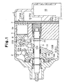
- the swash plate compressor is comprised of a cylinder block 1, a front housing 2 joined to the front end of the cylinder block 1, and a rear housing 4 joined to the rear end of the cylinder block 1 via a valve plate 3. These components are secured to each other by a plurality of bolts, not shown, to form a housing of the compressor.
- a crankcase 5 Within the housing, there are defined a crankcase 5, a suction chamber 6, and a discharge chamber 7.
- the cylinder block 1 is formed with a plurality of cylinder bores la (only one of which is shown), and each cylinder bore la has a single-headed piston 8 housed therein such that the piston 8 reciprocates.
- the suction chamber 6 and the discharge chamber 7 can selectively communicate with the respective cylinder bores la via various flap valves formed in the valve plate 3.
- a drive shaft 9 is rotatably supported, and a swash plate 10 is accommodated.
- the swash plate 10 has a central through hole 10a, and the drive shaft 9 extends through the through hole 10a.
- the swash plate 10 is connected to the drive shaft 9 via a hinge mechanism 13 and a lug plate 11, such that the swash plate 10 rotates integrally with the drive shaft 9.
- the swash plate 10 rotates in unison with the drive shaft 9 and, at the same time, may incline with respect to the drive shaft 9 while sliding in the axial direction.
- the outer periphery of the swash plate 10 is slidably engaged with an end of each piston 8 via a pair of front and rear shoes 20A, 20B, and all the pistons 8 are operatively connected to the swash plate 10.
- each piston 8 is caused to reciprocate by a stroke that corresponds to the inclination angle of the swash plate 10.
- suction of refrigerant gas from the suction chamber 6 region of suction pressure Ps
- the swash plate 10 is urged by an inclination-decreasing spring 14 toward the cylinder block (i.e. in an inclination-decreasing direction).
- the inclining and sliding motion of the swash plate 10 in the inclination-decreasing direction is restricted by, for example, a circlip 15, which is fitted on the drive shaft 9, whereby the minimum inclination angle ⁇ min (e.g., within a range of 3 to 5 degrees) of the swash plate 10 is set.
- the maximum inclination angle ⁇ max of the swash plate 10 is limited, e.g., by abutment of a counter-weight portion 10b of the swash plate on a stopper portion lla of the lug plate 11.
- the inclination angle of the swash plate 10 is determined based on a mutual balance among various moments, such as a turning moment based on centrifugal force produced by rotation of the swash plate, a moment based on a resilient force produced by the inclination-decreasing spring 14, a moment based on the inertial force of reciprocating motion of each piston, and a moment based on gas pressure.
- crank pressure Pc crank pressure
- the moment based on gas pressure is produced based on the relationship between the internal pressure within the cylinder bores and the internal pressure within the crankcase (crank pressure Pc), which corresponds to the back pressure of the corresponding piston.
- the moment acts in the inclination-decreasing direction or in the inclination-increasing direction depending on the crank pressure Pc.
- a control valve 16 not shown, to set the inclination angle of the swash plate 10 to a desired angle ⁇ between the minimum inclination angle ⁇ min and the maximum inclination angle ⁇ max.
- the swash plate 10 has annular sliding contact surfaces 30A, 30B formed on the respective front and rear sides of the outer periphery thereof.
- the annular front and rear sliding contact surfaces 30A, 30B are in sliding contact with the pair of shoes 20A, 20B, respectively.
- the swash plate 10 is made of a relatively heavy ferrous material (e.g. a cast iron such as FCD700) to properly generate the turning moment based on the centrifugal force produced by rotation of the swash plate 10.
- the shoes 20A, 20B are also made of a ferrous material (e.g. bearing steel) in view of mechanical strength.
- coatings 31A, 31B are formed at least on the respective sliding contact surfaces 30A, 30B of the swash plate 10 to form sliding layers for improving sliding contact between the sliding contact surfaces 30A, 30B and the shoes. That is, in the present embodiment, the sliding contact surfaces 30A, 30B of the swash plate 10 each form a work surface.
- the coatings 31A, 31B are each made of a different kind of metal material from the ferrous material used as a base material of the swash plate 10 and from that forming the shoes 20A, 20B.
- the metal material forming the coatings 31A, 31B may be an aluminum alloy containing silicon or an intermetallic compound of aluminum and silicon (hereinafter both referred to as "the Al-Si metal material"), or a copper-based material.
- the Al-Si metal material as the aluminum-based material, physical properties thereof, such as hardness and a melting point, vary with its silicon content.
- the Al-Si metal material used here has a silicon content of 15 to 20 wt%.
- the coatings 31A, 31B By forming the coatings 31A, 31B with the Al-Si metal material, it is possible not only to prevent seizure due to the aforementioned same metal phenomenon but also to improve sliding contact between the swash plate 10 and the shoes 20A, 20B. That is, the coatings 31A, 31B so formed make it possible to ensure a certain degree of lubrication between the swash plate 10 and the shoes 20A, 20B even under oil-free circumstances.
- the ferrous materials forming the swash plate 10 and the shoes 20A, 20B are very hard and each have a relatively high melting point, above one thousand and several hundred °C (e.g. above approximately 1500°C), whereas the Al-Si metal material forming the coatings 31A, 31B is softer than the ferrous materials and has a melting point of approximately 600°C to 700°C, which is lower than those of the ferrous materials.
- the differences in physical properties between the Al-Si metal material and the ferrous materials contribute to improving of the sliding contact between the swash plate 10 and the shoes 20A, 20B. Further, the differences in physical properties are very important in the determination of use of a method of forming a coating, described hereafter.
- a feed form 40 is prepared.
- the feed form 40 is formed entirely of the Al-Si metal material and has a hollow cylindrical shape and a thick wall.
- One end face 41 of the feed form 40 is an annular end face corresponding to the annular sliding contact surface 30B (or 30A) of the swash plate 10. Therefore, when the end face 41 of the feed form 40 is joined to the sliding contact surface 30B of the swash plate 10, the end face 41 covers the whole sliding contact surface 30B.
- a second step pressure-welding step
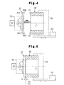
- the swash plate 10 is fitted on a rotary holding mechanism 51 (conceptually shown by two-dot-chain lines), while the feed form 40 is fitted in a sliding and holding mechanism 52 (conceptually shown by two-dot-chain lines).
- the rotary holding mechanism 51 is connected to a motor M such that it rotates integrally with the motor M, to rotate the swash plate 10 about an axis L by torque from the motor M.
- the annular sliding contact surface 30B is on a plane orthogonal to the axis L and opposed to the end face 41 of the feed form and spaced from the feed form.
- the sliding and holding mechanism 52 is connected to a sliding device 53 such that it moved integrally with the sliding device 53.
- the sliding and holding mechanism 52 is operated to bring the feed form 40 into contact with the swash plate 10, to press the feed form 40 against the swash plate 10, and to move the feed form 40 away from the swash plate 10.
- an axis L' of the feed form 40 and the axis L of the swash plate 10 coincide with each other, and when the feed form 40 is moved forward to the swash plate 10, the end face 41 is brought into face-to-face contact with the sliding contact surface 30B of the swash plate.
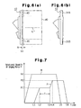
- the motor M and the rotary holding mechanism 51 are operated to rotate the swash plate 10 at a predetermined rotational speed N1 (e.g., at a rotational speed equal to or higher than 1800 rpm) as shown in Fig. 7. More specifically, a relative difference in speed in a circumferential direction is produced between the feed form 40, which is stationary, and the swash plate 10 to cause relative rotation about the common axis L and L' between the feed form 40 and the swash plate 10. Then, while maintaining the rotation of the swash plate 10, the sliding device 53 is operated to move the feed form 40 toward the swash plate 10 together with the sliding holding mechanism 52 until the end face 41 is brought into contact with the sliding contact surface 30B.
- N1 e.g., at a rotational speed equal to or higher than 1800 rpm
- the feed form 40 is further urged in the advancing direction and the force P of the feed form 40 against the swash plate 10 is increased to a final force P2 (time t4).
- the cylindrical end portion of the feed form 40 undergoes plastic deformation such that it expands radially outward and inward, and at the same time, the feed form 40 is reliably joined to the swash plate 10.
- the rotation of the swash plate 10 and the feed form 40 is stopped (time t5), and then, the force P is removed (time t6). Then, after the lapse of a predetermined cooling time period or without any particular cooling time period, the processing proceeds to a third step.
- the feed form 40 is cut from the swash plate 10.
- the operation for cutting off the feed form 40 is carried out at a cutting position S2, which is offset toward the feed form 40 from a joint position S1 by a predetermined distance R.
- a cutting tool not shown, such as a turning tool for use in machining or a cutter device, not shown, is used for the cutting.
- the feed form 40 is cut at the cutting position S2 in a direction orthogonal to the axis L'. In other words, the feed form 40 is cut and separated into a front portion and a rear portion along a plane orthogonal to the axis L'(see Fig. 6(A)).
- the distance R between the joint position S1 and the cutting position S2 corresponds to a length obtained by adding together the required thickness of the coating 31B and the thickness of a portion to be cut away in surface finishing, which is described below.
- the distance (or the thickness) R is within a range of 200 to 400. ⁇ m (micrometers).
- a fourth step surface finishing step
- surface finishing is performed on a preliminary coating (a soft metal layer made of the Al-Si metal material and having the thickness of R) formed on the sliding contact surface 30B of the swash plate 10.
- a preliminary coating a soft metal layer made of the Al-Si metal material and having the thickness of R
- lathe machining by a tool, such as a triangular tip, and polishing can be employed.
- a rough surface of the preliminary coating is removed, and the coating 31B is finished to have a desired thickness (e.g., 10 to 150 ⁇ m, and more preferably, 50 to 100 ⁇ m) and a smooth surface (see Fig. 6(B)).
- the third and fourth steps may be carried out at another worksite by removing the swash plate 10 from the rotary holding mechanism 51.
- the method of forming a coating according to this embodiment makes it possible to form the coatings 31A, 31B made of the Al-Si metal material on the respective sliding contact surfaces 30A, 30B of the swash plate 10 efficiently in a relatively short time by following a simple procedure.
- the present method does not require any special pretreatment to be effected on the work surfaces of the swash plate 10. Further, since the shape of each work surface and that of the end face of the feed form 40 are made correspondent to each other, no special masking or the like is required, either. Therefore, it is possible to largely reduce the labor, time and cost required for the operations.
- the present method is a versatile coating-forming technique because the coating 31A or 31B is applied or added to the work surface basically by making a physical joint by pressure welding, which requires no close chemical affinity.
- the feed form 40 is cut into the front and rear portions at the cutting position S2 after the feed form 40 is pressure-welded to the swash plate 10, and the preliminary coating is added to the work surface of the swash plate 10. Accordingly, it is possible to set the thickness R of the preliminary coating to a dimension that includes the final thickness of the coating 31A or 31B and that of the portion to be removed by surface finishing, which makes it easy to adjust the coating thickness as desired while ensuring the smoothness of the surface of the coating 31A or 31B.
- the swash plate 10 is rotated while the feed form 40 is displaced, this is not limitative.
- the feed form 40 may be rotated, and the swash plate 10 may be displaced.
- the swash plate 10 and the feed form 40 may be rotated at different rotational speeds, respectively, such that a relative difference in rotational speed is produced between the swash plate 10 and the feed form 40, and pressed against each other.
- the portions or sites to which the method of the present invention can be applied are not limited to the sliding contact surfaces 30A, 30B of the swash plate 10.
- Al-Si metal coatings may be similarly formed on the plane surfaces of the shoes 20A, 20B, which contact the respective sliding contact surfaces of the swash plate.
- a solid lubricant coating containing a solid lubricant such as molybdenum sulfide or the like, may be formed on the soft metal layer.
- the method according to the present invention is a very versatile technique of forming a coating for a metal material on a work surface of a machine component. Further, the method makes it possible to preserve an excellent working environment and at the same time effectively reduce the labor, time, and cost required for the operations. Moreover, the present invention facilitates control of the thickness of a coating.
Landscapes
- Chemical & Material Sciences (AREA)
- Engineering & Computer Science (AREA)
- Mechanical Engineering (AREA)
- Chemical Kinetics & Catalysis (AREA)
- Materials Engineering (AREA)
- Metallurgy (AREA)
- Organic Chemistry (AREA)
- General Engineering & Computer Science (AREA)
- Compressors, Vaccum Pumps And Other Relevant Systems (AREA)
Abstract
A method of forming a coating on a work surface of a
machine component. The method includes a preparatory step
of preparing a feed form formed of a metal material that is
softer than at least a work surface of a machine component,
a pressure-welding step of pressure-welding an end face of
the feed form to the work surface of the machine component
while causing relative rotation between the machine
component and the feed form, to join the feed form to the
machine component, and a cutting step of cutting the feed
form in a direction substantially orthogonal to an axis of
the relative rotation at a portion near a joining position
at which the machine component and the feed form are joined,
to add a soft metal layer having a predetermined thickness
to the work surface of the machine component.
Description
This invention relates to a method of forming a coating
on a work surface of a machine component. The coating is of
a metal material that is softer than the work surface of the
machine component, and more particularly, to a method of
forming a coating on a surface of a swash plate for use in a
swash plate compressor to improve sliding contact between
the surface of the swash plate and shoes.
Within a swash plate compressor, lubrication between
sliding contact members that form an internal mechanism is
generally provided by forming a mist of a lubricating oil in
the compressor by using a gas (e.g. a refrigerant gas such
as chlorofluorocarbon gas) flowing in the compressor, in
accordance with operation of the compressor, and delivering
the oil in the form of mist to the respective sliding
contact members. However, at a restart of the compressor,
for instance, after it has been left in an inoperative state
for a long time, lubricating oil attached to the sliding
contact members has often been washed away by the
refrigerant gas. For this reason, immediately after the
restart of the compressor, the sliding contact members,
which need lubrication, are insufficiently oiled, in spite
of operation of the compressor, over a time period
(approximately one minute) until a sufficient mist of oil is
formed by refrigerant gas that returns to the compressor.
Therefore, conventionally, there have been proposed
techniques of coating the surfaces of the sliding contact
members to ensure minimum lubrication between the sliding
contact members even when they are insufficiently oiled
during the above-mentioned time period.
Conventionally, various techniques have been proposed,
even in a limited field of art, in which a coating is formed
on surfaces of a swash plate, more specifically, surfaces of
a swash plate in sliding contact with shoes. Coating
techniques not only disclosed in patent documents but also
employed on products (swash plate) include electrolytic and
electroless plating techniques using tin or the like and a
spray coating technique using a copper-based alloy, an
aluminum-based alloy, or the like.
In the electrolytic or electroless plating technique
using tin, however, an extremely thin coating having a
thickness of several micrometers (e.g. 1 to 10 µm) can be
formed without much difficulty, whereas a relatively thick
coating having a thickness of several tens of micrometers
(e.g. 20 to 70 µm) cannot always be formed with ease.
Further, in this plating technique, the electro-chemical
relationship between the base material and the metal to be
deposited matters and can present problems. Thus, the
technique cannot always be employed.
On the other hand, a spray coating technique, in which
metal material in powder form is melted and sprayed together
with flame onto a work surface does not encounter
significant difficulties with regard to coating thickness or
electro-chemical relationship. However, the technique
suffers from the following intrinsic problems in operations:
In many cases, it is required to roughen the surface of a
work surface of a machine component by shot blasting or the
like before providing spray coating. Time and labor
required for the pretreatment and a cost for hard particles
(auxiliary material) used in the surface roughening
treatment are factors increasing the time and cost for the
spray coating. Further, considerable noise is generated
during the surface roughening treatment, which degrades the
working environment. Moreover, before providing spray
coating, it is required to mask portions that do not need
spraying, which further increases the time and cost. As
described above, in spite of its high general versatility as
a technique for forming a metal coating on a metal work
surface, the spray coating technique has many problems to be
solved with respect to the working environment on the shop
floor as well as the labor, time and cost.
It is an object of the present invention to provide a
method of forming a coating that is versatile, improves the
working environment, and reduces the required labor, time
and cost. Further, it is another object to provide a method
of forming a coating that facilitates control of thickness
of the coating.
The gist of the present invention consists in a method
of forming a coating on a work surface of a machine
component including a preparatory step of preparing a feed
form made of a metal material softer than at least a work
surface of the machine component, a pressure-welding step of
pressure-welding an end face of the feed form to the work
surface of the machine component while causing relative
rotation between the machine component and the feed form, to
thereby join the feed form to the machine component, and a
cutting step of cutting the feed form in a direction
substantially orthogonal to an axis of the relative rotation
at a position near a joining position at which the machine
component and the feed form are joined to each other, to
thereby add a soft metal layer having a predetermined
thickness to the work surface of the machine component.
According to this method, a soft metal layer having a
predetermined thickness is formed on the work surface of the
machine component by joining the machine component and the
feed form to each other by friction welding, and
subsequently cutting the feed form. Therefore, by selecting
a cutting position for cutting the feed form as desired, it
is possible to control the thickness of a metal coating on
the work surface with ease. Further, it is possible to form
a metal material coating having a desired thickness on the
work surface of the machine component with ease at low cost.
Preferably, the method further comprises a surface-finishing
step of carrying out surface finishing of the soft
metal layer added to the work surface of the machine
component. By providing the surface-finishing step after
the cutting step, it is possible not only to improve the
smoothness of the surface of the soft metal layer, but also
to widen a range of selection in determining the cutting
position for cutting the feed form, thereby facilitating the
operation for cutting the feed form.
Preferably, the metal material forming the feed form
has a lower melting point than the material forming the
machine component. Also preferably, the material forming
the machine component is a ferrous material while the metal
material forming the feed form is an aluminum-based material
or a copper-based material.
For example, the machine component is a swash plate for
use in a swash plate compressor. The method of the present
invention is an extremely suitable method of forming a
coating on a surface of the swash plate. Preferably, the
work surface of the swash plate machine component is a
surface that makes sliding contact with a shoe.
The method may further include forming a solid
lubricant coating containing a solid lubricant, such as
molybdenum sulfide, on a surface of the soft metal layer
added to the work surface of the machine component.
First, a brief description will be made of an example
of a variable capacity swash plate compressor to which the
present invention is applied. As shown in Fig. 1, the swash
plate compressor is comprised of a cylinder block 1, a front
housing 2 joined to the front end of the cylinder block 1,
and a rear housing 4 joined to the rear end of the cylinder
block 1 via a valve plate 3. These components are secured
to each other by a plurality of bolts, not shown, to form a
housing of the compressor. Within the housing, there are
defined a crankcase 5, a suction chamber 6, and a discharge
chamber 7. The cylinder block 1 is formed with a plurality
of cylinder bores la (only one of which is shown), and each
cylinder bore la has a single-headed piston 8 housed therein
such that the piston 8 reciprocates. The suction chamber 6
and the discharge chamber 7 can selectively communicate with
the respective cylinder bores la via various flap valves
formed in the valve plate 3.
Within the crankcase 5, a drive shaft 9 is rotatably
supported, and a swash plate 10 is accommodated. The swash
plate 10 has a central through hole 10a, and the drive shaft
9 extends through the through hole 10a. The swash plate 10
is connected to the drive shaft 9 via a hinge mechanism 13
and a lug plate 11, such that the swash plate 10 rotates
integrally with the drive shaft 9. The swash plate 10
rotates in unison with the drive shaft 9 and, at the same
time, may incline with respect to the drive shaft 9 while
sliding in the axial direction. Further, the outer
periphery of the swash plate 10 is slidably engaged with an
end of each piston 8 via a pair of front and rear shoes 20A,
20B, and all the pistons 8 are operatively connected to the
swash plate 10.
As the swash plate 10, which is inclined by a
predetermined angle, rotates in unison with the drive shaft
9, each piston 8 is caused to reciprocate by a stroke that
corresponds to the inclination angle of the swash plate 10.
In each bore 1a, suction of refrigerant gas from the suction
chamber 6 (region of suction pressure Ps), compression of
the refrigerant gas, and delivery of the refrigerant gas to
the discharge chamber 7 (region of discharge pressure Pd)
are sequentially and repeatedly carried out.
The swash plate 10 is urged by an inclination-decreasing
spring 14 toward the cylinder block (i.e. in an
inclination-decreasing direction). However, the inclining
and sliding motion of the swash plate 10 in the inclination-decreasing
direction is restricted by, for example, a
circlip 15, which is fitted on the drive shaft 9, whereby
the minimum inclination angle min (e.g., within a range of
3 to 5 degrees) of the swash plate 10 is set. On the other
hand, the maximum inclination angle max of the swash plate
10 is limited, e.g., by abutment of a counter-weight portion
10b of the swash plate on a stopper portion lla of the lug
plate 11. The inclination angle of the swash plate 10 is
determined based on a mutual balance among various moments,
such as a turning moment based on centrifugal force produced
by rotation of the swash plate, a moment based on a
resilient force produced by the inclination-decreasing
spring 14, a moment based on the inertial force of
reciprocating motion of each piston, and a moment based on
gas pressure.
The moment based on gas pressure is produced based on
the relationship between the internal pressure within the
cylinder bores and the internal pressure within the
crankcase (crank pressure Pc), which corresponds to the back
pressure of the corresponding piston. The moment acts in
the inclination-decreasing direction or in the inclination-increasing
direction depending on the crank pressure Pc.
In the swash plate compressor shown in Fig. 1, it is
possible to change the moment produced by the gas pressure
as desired by adjusting the crank pressure Pc with a control
valve 16, not shown, to set the inclination angle of the
swash plate 10 to a desired angle between the minimum
inclination angle min and the maximum inclination angle
max.
In the compressor constructed as above, one of the
machine components to be coated is e.g. the swash plate 10.
As shown in Figs. 1 to 3, the swash plate 10 has annular
sliding contact surfaces 30A, 30B formed on the respective
front and rear sides of the outer periphery thereof. The
annular front and rear sliding contact surfaces 30A, 30B are
in sliding contact with the pair of shoes 20A, 20B,
respectively. The swash plate 10 is made of a relatively
heavy ferrous material (e.g. a cast iron such as FCD700) to
properly generate the turning moment based on the
centrifugal force produced by rotation of the swash plate
10. The shoes 20A, 20B are also made of a ferrous material
(e.g. bearing steel) in view of mechanical strength. If the
two components (the swash plate and the shoe in the present
embodiment) are formed of materials of the same kind and are
brought into sliding contact with each other under severe
conditions, seizure of the components occurs due to so-called
"same metal phenomenon." Therefore, in the present
embodiment, coatings 31A, 31B are formed at least on the
respective sliding contact surfaces 30A, 30B of the swash
plate 10 to form sliding layers for improving sliding
contact between the sliding contact surfaces 30A, 30B and
the shoes. That is, in the present embodiment, the sliding
contact surfaces 30A, 30B of the swash plate 10 each form a
work surface.
The coatings 31A, 31B are each made of a different kind
of metal material from the ferrous material used as a base
material of the swash plate 10 and from that forming the
shoes 20A, 20B. The metal material forming the coatings
31A, 31B may be an aluminum alloy containing silicon or an
intermetallic compound of aluminum and silicon (hereinafter
both referred to as "the Al-Si metal material"), or a
copper-based material. In the case of the Al-Si metal
material as the aluminum-based material, physical properties
thereof, such as hardness and a melting point, vary with its
silicon content. The Al-Si metal material used here has a
silicon content of 15 to 20 wt%. By forming the coatings
31A, 31B with the Al-Si metal material, it is possible not
only to prevent seizure due to the aforementioned same metal
phenomenon but also to improve sliding contact between the
swash plate 10 and the shoes 20A, 20B. That is, the
coatings 31A, 31B so formed make it possible to ensure a
certain degree of lubrication between the swash plate 10 and
the shoes 20A, 20B even under oil-free circumstances.
In this connection, the ferrous materials forming the
swash plate 10 and the shoes 20A, 20B are very hard and each
have a relatively high melting point, above one thousand and
several hundred °C (e.g. above approximately 1500°C), whereas
the Al-Si metal material forming the coatings 31A, 31B is
softer than the ferrous materials and has a melting point of
approximately 600°C to 700°C, which is lower than those of
the ferrous materials. No doubt, the differences in
physical properties between the Al-Si metal material and the
ferrous materials contribute to improving of the sliding
contact between the swash plate 10 and the shoes 20A, 20B.
Further, the differences in physical properties are very
important in the determination of use of a method of forming
a coating, described hereafter.
Next, detailed description will be made of a procedure
for forming the coating 31B on the rear sliding contact
surface (work surface) 30B of the swash plate machine
component 10. The coating 31A is similarly formed on the
front sliding contact surface 30A by following the steps
described below.
In a first step (preparatory step), a feed form 40, as
shown in Fig. 3, is prepared. The feed form 40 is formed
entirely of the Al-Si metal material and has a hollow
cylindrical shape and a thick wall. One end face 41 of the
feed form 40 is an annular end face corresponding to the
annular sliding contact surface 30B (or 30A) of the swash
plate 10. Therefore, when the end face 41 of the feed form
40 is joined to the sliding contact surface 30B of the swash
plate 10, the end face 41 covers the whole sliding contact
surface 30B.
In a second step (pressure-welding step), as shown in
Fig. 4, the swash plate 10 is fitted on a rotary holding
mechanism 51 (conceptually shown by two-dot-chain lines),
while the feed form 40 is fitted in a sliding and holding
mechanism 52 (conceptually shown by two-dot-chain lines).
The rotary holding mechanism 51 is connected to a motor M
such that it rotates integrally with the motor M, to rotate
the swash plate 10 about an axis L by torque from the motor
M. When the swash plate is fitted on the rotary holding
mechanism 51, the annular sliding contact surface 30B is on
a plane orthogonal to the axis L and opposed to the end face
41 of the feed form and spaced from the feed form. On the
other hand, the sliding and holding mechanism 52 is
connected to a sliding device 53 such that it moved
integrally with the sliding device 53. The sliding and
holding mechanism 52 is operated to bring the feed form 40
into contact with the swash plate 10, to press the feed form
40 against the swash plate 10, and to move the feed form 40
away from the swash plate 10. When the feed form 40 is held
in the sliding mechanism 52, an axis L' of the feed form 40
and the axis L of the swash plate 10 coincide with each
other, and when the feed form 40 is moved forward to the
swash plate 10, the end face 41 is brought into face-to-face
contact with the sliding contact surface 30B of the swash
plate.
After the swash plate 10 and the feed form 40 have been
fixed in the respective mechanisms 51, 52, the motor M and
the rotary holding mechanism 51 are operated to rotate the
swash plate 10 at a predetermined rotational speed N1 (e.g.,
at a rotational speed equal to or higher than 1800 rpm) as
shown in Fig. 7. More specifically, a relative difference
in speed in a circumferential direction is produced between
the feed form 40, which is stationary, and the swash plate
10 to cause relative rotation about the common axis L and L'
between the feed form 40 and the swash plate 10. Then,
while maintaining the rotation of the swash plate 10, the
sliding device 53 is operated to move the feed form 40
toward the swash plate 10 together with the sliding holding
mechanism 52 until the end face 41 is brought into contact
with the sliding contact surface 30B.
Even after time tl in Fig. 7 when the feed form 40 has
been brought into contact with the swash plate 10, the feed
form 40 is urged in an advancing direction, and a force P of
the feed form 40 against the swash plate 10 is increased to
an intermediate force P1. Then, the intermediate pressure
P1 is held over a predetermined time period T (T = t3 - t2).
By causing the swash plate 10 and the feed form 40 to
perform relative rotation over the predetermined time period
T while maintaining the intermediate force P1, the Al-Si
metal material of the feed form 40 is melted to conform to
the ferrous material of the swash plate 10. As a result, a
diffusion layer formed by mutual diffusion of elements of
constituents of the material of the swash plate 10 and the
material of the feed form 40 is formed in the contact area
(or interface) between the swash plate 10 and the feed form
40.
After the predetermined time period T, the feed form 40
is further urged in the advancing direction and the force P
of the feed form 40 against the swash plate 10 is increased
to a final force P2 (time t4). At this time, as shown in
Fig. 5, the cylindrical end portion of the feed form 40
undergoes plastic deformation such that it expands radially
outward and inward, and at the same time, the feed form 40
is reliably joined to the swash plate 10. When the force P
has reached the final force P2, the rotation of the swash
plate 10 and the feed form 40 is stopped (time t5), and
then, the force P is removed (time t6). Then, after the
lapse of a predetermined cooling time period or without any
particular cooling time period, the processing proceeds to a
third step.
In the third step (cutting step), the feed form 40 is
cut from the swash plate 10. The operation for cutting off
the feed form 40 is carried out at a cutting position S2,
which is offset toward the feed form 40 from a joint
position S1 by a predetermined distance R. A cutting tool,
not shown, such as a turning tool for use in machining or a
cutter device, not shown, is used for the cutting. The feed
form 40 is cut at the cutting position S2 in a direction
orthogonal to the axis L'. In other words, the feed form 40
is cut and separated into a front portion and a rear portion
along a plane orthogonal to the axis L'(see Fig. 6(A)). The
distance R between the joint position S1 and the cutting
position S2 corresponds to a length obtained by adding
together the required thickness of the coating 31B and the
thickness of a portion to be cut away in surface finishing,
which is described below. Preferably, the distance (or the
thickness) R is within a range of 200 to 400. µm
(micrometers).
In a fourth step (surface-finishing step), surface
finishing is performed on a preliminary coating (a soft
metal layer made of the Al-Si metal material and having the
thickness of R) formed on the sliding contact surface 30B of
the swash plate 10. For the surface finishing, lathe
machining by a tool, such as a triangular tip, and polishing
can be employed. By carrying out the surface finishing, a
rough surface of the preliminary coating is removed, and the
coating 31B is finished to have a desired thickness (e.g.,
10 to 150 µm, and more preferably, 50 to 100 µm) and a
smooth surface (see Fig. 6(B)). The third and fourth steps
may be carried out at another worksite by removing the swash
plate 10 from the rotary holding mechanism 51.
According to the present embodiment, it is possible to
achieve the following effects:
The method of forming a coating according to this
embodiment makes it possible to form the coatings 31A, 31B
made of the Al-Si metal material on the respective sliding
contact surfaces 30A, 30B of the swash plate 10 efficiently
in a relatively short time by following a simple procedure.
Differently from the conventional spray coating
technique, the present method does not require any special
pretreatment to be effected on the work surfaces of the
swash plate 10. Further, since the shape of each work
surface and that of the end face of the feed form 40 are
made correspondent to each other, no special masking or the
like is required, either. Therefore, it is possible to
largely reduce the labor, time and cost required for the
operations.
Since no especially large noise is produced during the
operation for the pressure welding of the feed form 40 to
the swash plate 10, there is no fear of degrading the
working environment due to noise or the like.
The present method is a versatile coating-forming
technique because the coating 31A or 31B is applied or added
to the work surface basically by making a physical joint by
pressure welding, which requires no close chemical affinity.
In the present method, the feed form 40 is cut into the
front and rear portions at the cutting position S2 after the
feed form 40 is pressure-welded to the swash plate 10, and
the preliminary coating is added to the work surface of the
swash plate 10. Accordingly, it is possible to set the
thickness R of the preliminary coating to a dimension that
includes the final thickness of the coating 31A or 31B and
that of the portion to be removed by surface finishing,
which makes it easy to adjust the coating thickness as
desired while ensuring the smoothness of the surface of the
coating 31A or 31B.
The embodiment of the present invention may be modified
as follows:
Although in the above embodiment, the swash plate 10 is
rotated while the feed form 40 is displaced, this is not
limitative. The feed form 40 may be rotated, and the swash
plate 10 may be displaced. Alternatively, the swash plate
10 and the feed form 40 may be rotated at different
rotational speeds, respectively, such that a relative
difference in rotational speed is produced between the swash
plate 10 and the feed form 40, and pressed against each
other.
The portions or sites to which the method of the
present invention can be applied are not limited to the
sliding contact surfaces 30A, 30B of the swash plate 10.
Al-Si metal coatings may be similarly formed on the plane
surfaces of the shoes 20A, 20B, which contact the respective
sliding contact surfaces of the swash plate.
Further, after a soft metal layer with a predetermined
thickness is formed on each work surface, a solid lubricant
coating containing a solid lubricant, such as molybdenum
sulfide or the like, may be formed on the soft metal layer.
As described above in detail, the method according to
the present invention is a very versatile technique of
forming a coating for a metal material on a work surface of
a machine component. Further, the method makes it possible
to preserve an excellent working environment and at the same
time effectively reduce the labor, time, and cost required
for the operations. Moreover, the present invention
facilitates control of the thickness of a coating.
Claims (7)
- A method of forming a coating on a work surface of a machine component, the method comprising:a preparatory step of preparing a feed form made of a metal material softer than at least said work surface of said machine component;a pressure-welding step of pressure-welding an end face of said feed form to said work surface of said machine component while causing relative rotation between said machine component and said feed form, to thereby join said feed form to said machine component; anda cutting step of cutting said feed form in a direction substantially orthogonal to an axis of said relative rotation at a position near a joining position at which said machine component and said feed form are joined to each other, to thereby add a soft metal layer having a predetermined thickness to said work surface of said machine component.
- The method as claimed in claim 1, further comprising a surface-finishing step of carrying out surface finishing of said soft metal layer added to said work surface of said machine component.
- The method as claimed in claim 1 or 2, wherein said metal material forming said feed form has a lower melting point than a material forming said machine component.
- The method as claimed in any one of claims 1 to 3, wherein said material forming said machine component is a ferrous material while said metal material forming said feed form is an aluminum-based material or a copper-based material.
- The method as claimed in any one of claims 1 to 4, wherein said machine component is a swash plate for use in a swash plate compressor.
- The method as claimed in any one of claims 1 to 5, wherein said machine component is a rotary member which is rotatable about an axis, said rotary member having said work surface which is an annular or circular surface orthogonal to said axis, and wherein said end face of said feed form for being pressure-welded to said machine component has a shape corresponding to said annular or circular work surface of said machine component.
- The method as claimed in any one of claims 1 to 6, further comprising the step of forming a solid lubricant coating containing a solid lubricant, such as molybdenum sulfide, on a surface of said soft metal layer added to said work surface of said machine component.
Applications Claiming Priority (3)
| Application Number | Priority Date | Filing Date | Title |
|---|---|---|---|
| JP11212670A JP2001041150A (en) | 1999-07-27 | 1999-07-27 | Method of forming coating in mechanical part |
| JP21267099 | 1999-07-27 | ||
| PCT/JP2000/004936 WO2001007786A1 (en) | 1999-07-27 | 2000-07-25 | Method for forming film on machine part |
Publications (1)
| Publication Number | Publication Date |
|---|---|
| EP1116881A1 true EP1116881A1 (en) | 2001-07-18 |
Family
ID=16626465
Family Applications (1)
| Application Number | Title | Priority Date | Filing Date |
|---|---|---|---|
| EP00946476A Withdrawn EP1116881A1 (en) | 1999-07-27 | 2000-07-25 | Method for forming film on machine part |
Country Status (4)
| Country | Link |
|---|---|
| US (1) | US6471113B1 (en) |
| EP (1) | EP1116881A1 (en) |
| JP (1) | JP2001041150A (en) |
| WO (1) | WO2001007786A1 (en) |
Cited By (1)
| Publication number | Priority date | Publication date | Assignee | Title |
|---|---|---|---|---|
| US6543333B2 (en) | 2001-06-01 | 2003-04-08 | Visteon Global Technologies, Inc. | Enriched cobalt-tin swashplate coating alloy |
Families Citing this family (6)
| Publication number | Priority date | Publication date | Assignee | Title |
|---|---|---|---|---|
| KR100559808B1 (en) * | 2001-11-14 | 2006-03-15 | 가부시끼가이샤 도시바 | Inspection device and ultrasonograph |
| EP1575508A2 (en) * | 2002-07-11 | 2005-09-21 | The Trustees Of Columbia University In The City Of New York | Compositions and methods for the intracellular delivery of antibodies |
| US20090126182A1 (en) * | 2005-06-21 | 2009-05-21 | Tomokazu Hayashi | Separator, process for producing separator, and apparatus for producing separator |
| EP2098326B1 (en) | 2008-03-03 | 2016-01-06 | Ford Global Technologies, LLC | Method for producing a metallic component, manufactured component and use of the component |
| KR101840246B1 (en) * | 2013-10-16 | 2018-03-20 | 가부시키가이샤 고마쓰 세이사쿠쇼 | Sliding component, method for producing sliding component, and device for producing sliding component |
| DE102013221375A1 (en) * | 2013-10-22 | 2015-04-23 | Ford Global Technologies, Llc | Method for producing a coated bore surface, in particular a cylinder bore |
Family Cites Families (15)
| Publication number | Priority date | Publication date | Assignee | Title |
|---|---|---|---|---|
| GB474455A (en) * | 1936-05-06 | 1937-11-02 | Donald Stuart Leslie | Improved arrangement to facilitate storage of motor or other wheeled vehicles |
| US3824663A (en) * | 1973-02-07 | 1974-07-23 | Curtiss Wright Corp | Method of welding a tube to a tube sheet |
| JPS53129311A (en) * | 1977-04-19 | 1978-11-11 | Toyoda Autom Loom Works Ltd | Shoe for swash plate type compressor |
| JPS6026188A (en) * | 1983-07-20 | 1985-02-09 | Taiho Kogyo Co Ltd | Swash plate type compressor |
| JPH0697033B2 (en) * | 1988-11-11 | 1994-11-30 | 株式会社豊田自動織機製作所 | Swash plate type compressor |
| JPH085280B2 (en) | 1993-07-30 | 1996-01-24 | 利之 松岡 | Decorative material with natural wood pattern and manufacturing method thereof |
| JPH09122935A (en) * | 1995-10-26 | 1997-05-13 | Ishikawajima Harima Heavy Ind Co Ltd | Joining method of aluminum body and iron-based shaft and joined body |
| US5655432A (en) * | 1995-12-07 | 1997-08-12 | Ford Motor Company | Swash plate with polyfluoro elastomer coating |
| JP3463540B2 (en) * | 1996-11-21 | 2003-11-05 | 株式会社豊田自動織機 | Swash plate compressor |
| WO1998036173A1 (en) * | 1997-02-14 | 1998-08-20 | Kabushiki Kaisha Toyoda Jidoshokki Seisakusho | Swash plate compressor |
| US5858142A (en) * | 1997-02-27 | 1999-01-12 | Inertia Friction Welding, Inc. | Angular orientation control system for friction welding |
| JP4023872B2 (en) * | 1997-06-26 | 2007-12-19 | 大豊工業株式会社 | Swash plate compressor swash plate |
| DE69825951T2 (en) | 1997-10-24 | 2005-09-15 | Kabushiki Kaisha Toyota Jidoshokki, Kariya | The swash plate compressor |
| JPH11193780A (en) * | 1997-12-26 | 1999-07-21 | Toyota Autom Loom Works Ltd | Single-headed piston swash plate type compression machine and method for manufacturing swash plate |
| JP2000265284A (en) * | 1999-03-17 | 2000-09-26 | Toyota Autom Loom Works Ltd | Formation of film in machine parts |
-
1999
- 1999-07-27 JP JP11212670A patent/JP2001041150A/en active Pending
-
2000
- 2000-07-25 US US09/806,004 patent/US6471113B1/en not_active Expired - Fee Related
- 2000-07-25 EP EP00946476A patent/EP1116881A1/en not_active Withdrawn
- 2000-07-25 WO PCT/JP2000/004936 patent/WO2001007786A1/en not_active Ceased
Non-Patent Citations (1)
| Title |
|---|
| See references of WO0107786A1 * |
Cited By (1)
| Publication number | Priority date | Publication date | Assignee | Title |
|---|---|---|---|---|
| US6543333B2 (en) | 2001-06-01 | 2003-04-08 | Visteon Global Technologies, Inc. | Enriched cobalt-tin swashplate coating alloy |
Also Published As
| Publication number | Publication date |
|---|---|
| JP2001041150A (en) | 2001-02-13 |
| US6471113B1 (en) | 2002-10-29 |
| WO2001007786A1 (en) | 2001-02-01 |
Similar Documents
| Publication | Publication Date | Title |
|---|---|---|
| KR100367188B1 (en) | Oil Separating Structure of Compressor | |
| EP0943801B1 (en) | Swash plate compressor | |
| US6471113B1 (en) | Method of forming a coating on machine components | |
| EP1167761A2 (en) | Swash plate type compressor | |
| EP1134413A2 (en) | Swash plate for compressor | |
| EP1262662A1 (en) | Swash plate type compressor | |
| US6694864B2 (en) | Swash plate type compressor | |
| KR100327084B1 (en) | Swash plate compressor | |
| KR20010021103A (en) | Film forming method on the constitutional elements of compressor | |
| EP1036939A1 (en) | Method for forming a film on machine parts | |
| JP2002317758A (en) | Swash plate in swash plate-type compressor | |
| JP2006008994A (en) | Sliding coating, sliding member, sliding coating composition, sliding device, swash plate compressor, sliding coating forming method, and sliding member manufacturing method | |
| CN100395449C (en) | axial piston machine | |
| RU2210626C1 (en) | Process forming antifriction coat on metal surfaces of friction pairs | |
| JP2001248546A (en) | Method for forming coat in swash plate of swash plate compressor | |
| JP2768536B2 (en) | Axial plunger pump | |
| EP0961030A2 (en) | Lubrication for pistons in the crankcase of a swash plate type compressor | |
| EP1130259A2 (en) | Coating applied by electric arc welding for a compressor swash plate | |
| JP2002004063A (en) | Method of forming metallic film | |
| JP2001254675A (en) | Method for forming film on swash plate for swash plate type compressor | |
| JP2001098385A (en) | Film forming method for machine parts | |
| KR20180095248A (en) | Swash plate compressor and swash plate processing method | |
| JP2002206478A (en) | Piston for compressor and compressor using the same | |
| JPH11201038A (en) | Piston of compressor | |
| JP2018141392A (en) | Hydraulic rotating machine |
Legal Events
| Date | Code | Title | Description |
|---|---|---|---|
| PUAI | Public reference made under article 153(3) epc to a published international application that has entered the european phase |
Free format text: ORIGINAL CODE: 0009012 |
|
| 17P | Request for examination filed |
Effective date: 20010426 |
|
| AK | Designated contracting states |
Kind code of ref document: A1 Designated state(s): AT BE CH CY DE DK ES FI FR GB GR IE IT LI LU MC NL PT SE |
|
| RAP1 | Party data changed (applicant data changed or rights of an application transferred) |
Owner name: KABUSHIKI KAISHA TOYOTA JIDOSHOKKI |
|
| RBV | Designated contracting states (corrected) |
Designated state(s): DE FR IT |
|
| STAA | Information on the status of an ep patent application or granted ep patent |
Free format text: STATUS: THE APPLICATION IS DEEMED TO BE WITHDRAWN |
|
| 18D | Application deemed to be withdrawn |
Effective date: 20060201 |