EP1116819A2 - Drainage foil for a paper machine - Google Patents
Drainage foil for a paper machine Download PDFInfo
- Publication number
- EP1116819A2 EP1116819A2 EP00126840A EP00126840A EP1116819A2 EP 1116819 A2 EP1116819 A2 EP 1116819A2 EP 00126840 A EP00126840 A EP 00126840A EP 00126840 A EP00126840 A EP 00126840A EP 1116819 A2 EP1116819 A2 EP 1116819A2
- Authority
- EP
- European Patent Office
- Prior art keywords
- loading
- lath
- slide rail
- roller means
- wire
- Prior art date
- Legal status (The legal status is an assumption and is not a legal conclusion. Google has not performed a legal analysis and makes no representation as to the accuracy of the status listed.)
- Granted
Links
Images

Classifications
-
- D—TEXTILES; PAPER
- D21—PAPER-MAKING; PRODUCTION OF CELLULOSE
- D21F—PAPER-MAKING MACHINES; METHODS OF PRODUCING PAPER THEREON
- D21F1/00—Wet end of machines for making continuous webs of paper
- D21F1/48—Suction apparatus
- D21F1/483—Drainage foils and bars
- D21F1/486—Drainage foils and bars adjustable
Definitions
- the present invention relates to the web-forming section, that is, the former section, of a paper machine or similar, such as e.g. a board machine or a tissue machine. More specifically, the invention concerns a loading element in accordance with the introductory part of claim 1 for the dewatering lath of a web-forming wire for use to support and/or load the paper machine wire or wires and/or to scrape water from the surface of the wire or wires, and which lath is loaded through the pressure of a medium.
- a dewatering box which includes located opposite to each other a forming table and a dewatering box, which includes a set of laths with spaces between them through which water is removed from the web significantly by the effect of vacuum into a dewatering box, in which forming table there is at the dewatering box a set of loading laths in the transverse direction located at a considerable distance from each other in the machine direction, whereby in the area of the forming unit dewatering can be arranged to take place through both the covering and the carrying wire and also towards the forming table through the open spaces between its loading laths.
- the lath contains an end lath, which is located transversely to the direction of movement of the wire and over which the wire is able to slide.
- the end lath is fixedly attached to a supporting lath, which is also located transversely to the direction of movement of the wire and which is controlled to move in the fixed structure.
- a yielding impact device is arranged, which can move the movable support lath and the end lath located therein with a desired force against the wire.
- there are some control arms in the fixed structure divided along the length of the support lath to take a hold around the support lath like a clip, as seen in the transverse direction of the support lath.
- the invention aims at presenting a solution with which the problems of previously known solutions are eliminated or at least minimized.
- the present invention is based on the new and inventive idea that in order to prevent the jamming phenomenon of the lath part, such a pivoting roller or rollers or balls are used between the lath part and the loading element, which will prevent occurrence of the jamming phenomenon between the lath part and with the aid of which the static friction between the loading element and the lath part is converted into rolling friction that is essentially smaller than the sliding friction and the static friction.
- such a roller is fitted to the top end or the body part of the loading element, the periphery of which is against the lath part moving on the body part.
- the roller is pivoted in the lath part, whereby its periphery is supported against the body part.
- a pin is fitted to the top end of the body part of the loading element and, correspondingly, a ball bushing is fitted in the lath part, whereby the pin will roll along the balls of the ball bushing.
- the loading element which extends transversely to the direction of movement of the wire, that is, in the CD direction essentially over the entire width of the web forming section, includes a loading lath 41 in the CD direction and a body part 43 in the CD direction, of which the latter has a free top part in the CD direction forming a slide rail 44.
- the loading lath 41 which lengthwise has a longitudinal groove 54, is supported evenly in its position in the CD direction and is adapted to move towards and away from the wire supported by slide rail 44 and roller means 100.
- a planar and/or inclined ceramic piece 42 which when water functions as lubricating liquid will drag against the wire surface loading this, whereby water to be removed from the web is scraped by the loading lath 41 away from the lower surface of the wire.
- the roller means which in the CD direction includes one or more successive rollers, is mounted in the free top part of the slide rail 44 in the CD direction with the aid of one or more successive rotating shafts 110.
- the roller means will be referred to by the definition of roller.
- the loading lath 41 thus moves in the up-end-down direction in relation to slide rail 44.
- rolling friction is brought about according to the invention with the aid of roller 100 between body part 43, slide rail 44 and loading lath 41.
- roller 100 is pivoted to slide rail 44 of the loading element with the aid of rotating shaft 110.
- roller 100 and its rotating shaft 110 extend in the CD direction over the width of lath part 41, and rotating shaft 110 is pivoted at least at its ends to slide rail 44.
- roller supporting bearings not shown in Figure 1
- slide rail 44 which typically is integral with body part 43, has mutually spaced indentations (not shown in Figure 1), which are open towards loading lath 41 in order to shaft its supporting rollers 100 in the indentations.
- roller 100 To make sure that rolling friction is constantly maintained between roller 100 and the loading lath 41 of its stop surface, their fitting as well as that of lath 41 and body part 43 are made with a play whereby the force caused by the wire to overturn loading element 41, 43 is not allowed to bring about any friction force except on one side of roller 100.
- loading element 41 which extends transversely to the direction of movement of the wire, that is, in the CD direction, essentially over the entire width of the web forming section, includes a loading lath 41 in the CD direction and a body part 43 in the CD direction, whereby the top part of the latter in the CD direction forms a slide rail 44.
- loading lath 41 which lengthwise has a longitudinal groove 54, is supported evenly in its position in the CD direction and is adapted to move towards and away from the wire supported by slide rail 44 and by roller means 100, which are installed in the free top end of slide rail 44 with the aid of rotating shafts 110.
- roller means is referred to by the definition of roller.
- loading lath 41 thus moves in an up-and-down direction in relation to slide rail 44.
- rolling friction is brought about according to the invention with the aid of rollers 100 between body part 43, slide rail 44 and loading lath 41.
- rollers 100 are pivoted to body part 43 with the aid of rotating shafts 110.
- rollers 100 are mounted one each at either side of slide rail 44, whereby each roller 100 and their rotating shafts 110 extend in the CD direction over the width of loading lath 41 and rotating shafts 110 are pivoted to the slide rail 44 at least at their ends. It is hereby advantageous that over the length of each roller 100 supporting bearings (not shown in Figure 2) are tilted at an interval from each other, such as e.g. roller or slide bearings, in order to support rollers 100 between their ends.
- slide rail 44 which typically is an integral part with body part 43, has several rollers 100 and mutually spaced indentations (not shown in Figure 2), which are open towards loading lath 41 in order to shaft its supporting rollers 100 in the indentations.
- each roller 100 has only one stop face, whereby a constant rolling friction is maintained between loading lath 41 and rollers 100, and their mutual fitting can be made essentially with absence of play.
- the individual rollers 100 are made of a material, which withstands the pressure impact to which it is subjected and which significantly reduces friction that significantly impedes the movement of lath 41.
- a rotating shaft 110 pushed through roller 100 is attached to the slide rail in the longitudinal direction, and the body part 43 has dents, whereby rollers 100 are free to rotate in the said dents.
- rollers 100 at uniform intervals of 500 mm over the entire width of the lath, whereby the rollers are able to receive the forces to which they are subjected.
- both lath part 41 and body part 43 and slide rail 44 are made of glass fiber and, in addition, a wear-resistant ceramic piece 42 is mounted on the end of lath part 41.
- a friction-reducing slide piece 45 which reduces friction between lath part 41 and body part 43. It was found that this improves even more the easy movement of lath part 41.
- slide part 45 it is also possible to use ball/round bars in order to reduce friction even more between lath part 41 and body part 43.
- roller or rollers 100 with the aid of rotating shafts 110 may be pivoted instead of in the slide rail 44 also in loading lath 41, preferably in the internal cavity space of loading lath 41, wherein the slide rail 44 is also located.
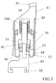
- loading element 41 which extends transversely to the direction of movement of the wire, that is, in the CD direction essentially over the entire width of the web forming part, includes a loading lath 41 in the CD direction and a body part 43 in the CD direction, whereby the top part of the latter has a slide part/parts 44, in relation to which loading lath 41 moves towards and away from the wire.
- the loading lath 41 which lengthwise has a longitudinal groove 54, is supported evenly in its position in the CD direction and is adapted to move supported by slide part/parts 44 and ball means 100, which are mounted in the free top part/parts of slide part/parts 44.
- ball means 100 using the definition of ball.
- water functions as lubricating liquid
- the planar and/or inclined upper side of loading lath 41 drags against the wire surface loading this, whereby with the aid of loading lath 41 water to be removed from the web is scraped away from the lower surface of the wire.
- loading lath 41 thus moves in an up-and-down direction in relation to slide part 44.
- rolling friction is brought about in accordance with the invention with the aid of balls 100 between body part 43, slide part 44 and loading lath 41.
- balls 100 are mounted to loading lath 41 with the aid of ball bushing 49.
- balls 100 are mounted in several rings on top of each other, whereby the stacks of adjacent ball rings, the mutual distance of which is preferably between 200 and 280 mm in the transverse machine direction, that is, in the CD direction, extend in the CD direction over the width of loading lath 41.
- slide parts 44 are formed by pins made in the top part of body part 43 and that the top parts of slide parts 44 are fitted with a play into ball bushings 49, which are attached to loading lath 41 and which also allow heat expansion.
- ball bushings 49 allow a relative movement between slide part 44 and loading lath 41 in the up-and-down direction, at the same time preventing slide part 44 and loading lath 41 from jamming.
- the balls 100 fitted into ball bushing 49 preferably form a bearing, the type of which is e.g. SKF LBBR 12-2LS/HV6.
- a flexible belt 46 is joined to the lower edge of loading lath 41, which belt is most suitably attached to the top part of body part 43 in such a way that U-shaped loops 48 are formed downward.
- To the sides of the lath 41 outside belt 46 are attached protecting plates 55 limiting the lateral movement of belt 46.
- Belts 46 are attached to lath 41 and, correspondingly, to a groove made in body part 43, preferably by a formed profile connection, the internal space 56 of which is designed for pressurization when required, whereby a simple and tight connection results.
- attaching elements 58 lath 41 is attached to the other body structures of the machine.
- the loading force of loading lath 41 is brought about by running a loading pressure with the aid of a medium, such as air, through channel 57 into the space limited by the flexible belt 46, lath 41 and body part 43.
- a medium such as air
- loading lath 41 is flexibly loaded, because the air is compressed.
- the loading pressure is reduced by lowering the pressure, and earth gravity will return lath 41 to its bottom position. It should be underlined, that vacuum may also be used to bring loading lath 41 back to its lower position.
- Belt 46 whose thickness is e.g.
- 0.1 - 3 mm preferably 1 - 2 mm, and which is made of rubber or some other corresponding and flexible material, is attached at its top edge to lath 41 and at its bottom edge to body part 43 by attaching parts 56 in such a way that U-shaped loops 48 are formed downward which allow lath 41 to move in an up-and-down direction in order to add to the loading of the wire and, correspondingly, in order to reduce the loading of the wire.
- Lateral supports 55 limit expansion of belt 46 laterally, whereby the surface area where the pressure is effective will not change as lath 41 is moving in the loading direction.
- the invention concerns a loading element for the dewatering lath of a web-forming wire, which supports and/or loads the wire of a paper machine or such and/or scrapes water from the wire surface, which is loaded by the pressure of a medium, and which includes a movable loading lath (41) and a fixed body part (43), whose free top part has a slide rail (44).
- the loading lath (41) is supported evenly in its position in the CL) direction and it is adapted to move towards the wire and away from the wire supported by a slide rail (44) and roller or ball means(100).
Landscapes
- Paper (AREA)
- Folding Of Thin Sheet-Like Materials, Special Discharging Devices, And Others (AREA)
- Bearings For Parts Moving Linearly (AREA)
Abstract
Description
The invention concerns a loading element for the dewatering lath of a web-forming wire, which supports and/or loads the wire of a paper machine or such and/or scrapes water from the wire surface, which is loaded by the pressure of a medium, and which includes a movable loading lath (41) and a fixed body part (43), whose free top part has a slide rail (44). In order to eliminate jamming phenomenon of the loading element, the loading lath (41) is supported evenly in its position in the CL) direction and it is adapted to move towards the wire and away from the wire supported by a slide rail (44) and roller or ball means(100).
Claims (15)
- Loading element for the dewatering lath of a web-forming wire, which supports and/or loads the wire of a paper machine or such, for example, a board or tissue machine, and/or scrapes water from the wire surface, which is loaded by pressure of a medium, and which includes a movable loading lath (41) and a fixed body part (43), characterized in that the loading lath (41) is adapted to move in relation to the body part (43) towards the wire and away from the wire supported by at least one roller or ball means (100).
- Loading element as defined in claim 1, characterized in that the roller means (100) is adapted to be supported against the loading lath (41) and to form rolling friction between the roller means (100) and the loading lath (41).
- Loading element as defined in claim 1 and/or 2, characterized in that the free top end of the body part (43) has a slide rail (44), to which the roller means (100) is a rotary fit, preferably with the aid of a rotating shaft (110), whereby the loading lath (41) moves towards and away from the wire supported by rolling means (100) fitted into the slide rail (44).
- Loading element as defined in claim 3, characterized in that there is one roller means (100) in the slide rail (44), whereby the roller means (100) and its rotating shaft (110) extend in the CD direction over the width of the loading lath (41) and the rotating shaft (110) is pivoted to the slide rail (44) at least at its ends.
- Loading element as defined in claim 3, characterized in that one rolling means (100) is arranged in the slide rail (44) at its both longitudinal sides, whereby the roller means (100) and their rotating shafts (110) extend in the CD direction over the width of the loading lath (41) and the rotating shafts (110) are pivoted to the slide rail (44) at least at its ends.
- Loading element as defined in claim 4 or 5, characterized in that between the ends of roller means (100) supporting bearings are fitted at mutual intervals in order to support the roller means (100) between its ends.
- Loading element as defined in claim 1, characterized in that there are several roller means (100) in succession in the slide rail (44) in the CD direction in at least one line, whereby the slide rail (44) has mutually spaced indentations, which are open towards the loading lath (41) in order to shaft the roller means (100) supported against the loading lath (41) with the aid of rotating shafts (110) in the said indentations in such a way that each line of roller means (100) is supported against the loading lath.
- Loading element as defined in claim 1, characterized in that the rolling means (100) is adapted to support against the body part (43) and to form rolling friction between the roller means (100) and the body part (43).
- Loading element as defined in claim 1 and/or 2, characterized in that the free top part of the body part (43) forms the slide rail (44) and that the roller means (100) is a rotary fit, preferably with the aid of a rotating shaft (11), in the loading lath (41), whereby the loading lath (41) moves towards and away from the wire supported by the roller means (100) fitted into the slide rail (44).
- Loading element as defined in any one of claims 1,2, 3 and/or 9, characterized in that at least one roller means (100) is a rotary fit, preferably with the aid of a rotating shaft (110), on both sides of the slide rail (44).
- Loading element as defined in any one of claims 1-10, characterized in that each roller means (100) of the loading element includes in the CD direction one or more successive rollers, that the roller means is fitted into the free top part of the slide rail (44) in the CD direction with the aid of one or more successive rotating shafts (110), whereby each loading element includes in the CD direction at least one rotating shaft (110), on to which at least one roller means (100) is pivoted.
- Loading element as defined in claim 1, characterized in that ball means (100) forms at least one ring of balls, which brings about rolling friction between the ball means (100) and the loading lath (41).
- Loading element as defined in claim 1 and/or 2, characterized in that the free top part of the body part (43) has at least one preferably pin-like slide part (44), around which is fitted at least one ball ring formed by rolling balls with the aid of a ball bushing (49), which is attached to the loading lath (41), whereby the loading lath (41) moves towards and away from the wire supported by the ball means (100).
- Loading element as defined in claim 12, characterized in that ball rings placed at intervals preferably of 200- 280 mm from each other are fitted several beside one another, and that the stacks of ball rings are fitted to extend in the CD direction over the width of the loading lath (41).
- Loading element as defined in any one of claims 1-9, characterized in that both the loading lath (41) and the body part (43) and the slide rail (44) are glass fiber, and that alternatively in order further to reduce friction impeding the movement of the loading lath:In the lower slide surface of the body part (43) there is a friction-reducing slide piece (45), orThere are balls/round bars between the lath part (41) and the body part (43).
Applications Claiming Priority (2)
| Application Number | Priority Date | Filing Date | Title |
|---|---|---|---|
| FI992699 | 1999-12-16 | ||
| FI992699 | 1999-12-16 |
Publications (3)
| Publication Number | Publication Date |
|---|---|
| EP1116819A2 true EP1116819A2 (en) | 2001-07-18 |
| EP1116819A3 EP1116819A3 (en) | 2001-10-31 |
| EP1116819B1 EP1116819B1 (en) | 2007-01-24 |
Family
ID=8555757
Family Applications (1)
| Application Number | Title | Priority Date | Filing Date |
|---|---|---|---|
| EP00126840A Expired - Lifetime EP1116819B1 (en) | 1999-12-16 | 2000-12-07 | Drainage foil for a paper machine |
Country Status (7)
| Country | Link |
|---|---|
| US (1) | US6780285B2 (en) |
| EP (1) | EP1116819B1 (en) |
| JP (1) | JP3488199B2 (en) |
| AT (1) | ATE352664T1 (en) |
| BR (1) | BR0006508A (en) |
| CA (1) | CA2328543C (en) |
| DE (1) | DE60033124T2 (en) |
Cited By (1)
| Publication number | Priority date | Publication date | Assignee | Title |
|---|---|---|---|---|
| DE212008000022U1 (en) | 2007-03-14 | 2009-11-19 | Metso Paper, Inc. | Resilient drainage element |
Families Citing this family (6)
| Publication number | Priority date | Publication date | Assignee | Title |
|---|---|---|---|---|
| DE102005000175A1 (en) * | 2005-12-05 | 2007-06-06 | Voith Patent Gmbh | Strip for the flexible support of a sieve and a double sieve section |
| DE102008040032A1 (en) * | 2008-06-30 | 2009-12-31 | Voith Patent Gmbh | Strip arrangement for a machine for producing a fibrous web |
| DE102008040688A1 (en) * | 2008-07-24 | 2010-01-28 | Voith Patent Gmbh | Method for optimizing the energy balance in forming units in machines for producing fibrous webs and forming unit |
| US9834887B2 (en) | 2015-04-10 | 2017-12-05 | Coldwater Seals, Inc. | Adjustable foil apparatus for paper making machine |
| US9879377B2 (en) | 2015-04-10 | 2018-01-30 | Coldwater Seals, Inc. | Adjustable foil apparatus for paper making machine |
| TWI629194B (en) * | 2016-01-22 | 2018-07-11 | 力能科技有限公司 | Battery electric vehicle |
Family Cites Families (11)
| Publication number | Priority date | Publication date | Assignee | Title |
|---|---|---|---|---|
| US2170109A (en) * | 1937-12-15 | 1939-08-22 | Beloit Iron Works | Forming wire support for paper machines |
| US3201308A (en) * | 1963-10-02 | 1965-08-17 | Dominion Eng Works Ltd | Adjustable drainage foil for paper machine |
| US3535204A (en) * | 1967-01-23 | 1970-10-20 | Dominion Eng Works Ltd | Foil mounting arrangement in a paper machine |
| DE4019884A1 (en) | 1990-06-22 | 1992-01-09 | Voith Gmbh J M | PERFORMANCE SUPPLY SUPPORT FOR A SCREENING BELT |
| DE4107653A1 (en) * | 1991-03-09 | 1992-09-10 | Escher Wyss Gmbh | DRAINAGE DEVICE FOR THE WET SECTION OF A PAPER MACHINE |
| FI90673C (en) | 1991-06-26 | 1994-03-10 | Valmet Paper Machinery Inc | Path forming section with double wire in a paper machine |
| US5169500A (en) * | 1991-10-15 | 1992-12-08 | Wilbanks International | Adjustable angle foil for paper making machine with rigid foil body and cam actuation means |
| DE4141607C2 (en) | 1991-12-17 | 1996-04-25 | Voith Gmbh J M | Twin wire former |
| AT400158B (en) * | 1993-12-21 | 1995-10-25 | Bartelmuss Klaus Ing | DEVICE FOR ADJUSTING THE ALTITUDE AND OR OR THE ANGLE POSITION OF A STRIP ASSIGNED TO THE SCREENING BELT OF A PAPER PRODUCTION PLANT |
| FI95935C (en) * | 1995-03-01 | 1996-04-10 | Valmet Corp | List for a dewatering device in a paper machine |
| JP3664857B2 (en) * | 1997-09-05 | 2005-06-29 | 三菱重工業株式会社 | Paper machine twin wire former dewatering equipment |
-
2000
- 2000-12-07 AT AT00126840T patent/ATE352664T1/en active
- 2000-12-07 DE DE60033124T patent/DE60033124T2/en not_active Expired - Lifetime
- 2000-12-07 EP EP00126840A patent/EP1116819B1/en not_active Expired - Lifetime
- 2000-12-15 BR BR0006508-0A patent/BR0006508A/en not_active Application Discontinuation
- 2000-12-15 CA CA002328543A patent/CA2328543C/en not_active Expired - Lifetime
- 2000-12-18 US US09/740,176 patent/US6780285B2/en not_active Expired - Lifetime
- 2000-12-18 JP JP2000383821A patent/JP3488199B2/en not_active Expired - Fee Related
Cited By (1)
| Publication number | Priority date | Publication date | Assignee | Title |
|---|---|---|---|---|
| DE212008000022U1 (en) | 2007-03-14 | 2009-11-19 | Metso Paper, Inc. | Resilient drainage element |
Also Published As
| Publication number | Publication date |
|---|---|
| DE60033124D1 (en) | 2007-03-15 |
| EP1116819A3 (en) | 2001-10-31 |
| ATE352664T1 (en) | 2007-02-15 |
| CA2328543C (en) | 2007-12-04 |
| DE60033124T2 (en) | 2007-11-15 |
| BR0006508A (en) | 2001-07-24 |
| US6780285B2 (en) | 2004-08-24 |
| US20010004006A1 (en) | 2001-06-21 |
| EP1116819B1 (en) | 2007-01-24 |
| JP3488199B2 (en) | 2004-01-19 |
| CA2328543A1 (en) | 2001-06-16 |
| JP2001192993A (en) | 2001-07-17 |
Similar Documents
| Publication | Publication Date | Title |
|---|---|---|
| FI75620B (en) | LAONGZONSPRESS FOER EN PAPPERSMASKIN. | |
| FI89286B (en) | PRESS MED LAONGT NYP | |
| FI89285C (en) | Long nip press | |
| CA1133300A (en) | Roll bearing alignment | |
| CA1166499A (en) | Extended nip shoe | |
| EP1116819B1 (en) | Drainage foil for a paper machine | |
| PT1403195E (en) | Trough for an air cushion conveyor | |
| KR900702246A (en) | Linear sliding bearing | |
| EP0612883A1 (en) | An arrangement in a dryer for a fibre web | |
| DE60013180D1 (en) | FASTENING DEVICE FOR DRAINAGE STRIPS IN A DOUBLE SCREEN FORMER | |
| TW333475B (en) | Roller frame for roller ramming steel strip the invention relates to a roller frame for roller ramming steel strip, which comprises axially movable working rollers which are supported to a support roller. | |
| KR870009068A (en) | Compression Rolling Device | |
| CA1277277C (en) | Chain scraper conveyor | |
| FI113788B (en) | Press | |
| FI76608C (en) | Long nip press | |
| JP4316709B2 (en) | Press machine | |
| FI100811B (en) | Paper machine dewatering device list | |
| RU2000106642A (en) | DEVICE FOR REGULATED INFLUENCE OF FRICTION FORCES BETWEEN GUIDING AND THRESHOLD SURFACES OF ROLLER SUPPORT PILLOWS INSTALLED IN OPENINGS OF ROLLING CELLS | |
| FI121889B (en) | Press roller with a press shoe that is removably installed on a holder | |
| KR200403753Y1 (en) | Pot bearing for a bridge | |
| FI109196B (en) | Separator for web rolls | |
| WO2004045996A1 (en) | Spiral guider - cleaner roller for conveyor belt | |
| FI104281B (en) | The shoe roll | |
| FI90263B (en) | Långzonspress | |
| DE3533774A1 (en) | Suspension for discharge devices |
Legal Events
| Date | Code | Title | Description |
|---|---|---|---|
| PUAI | Public reference made under article 153(3) epc to a published international application that has entered the european phase |
Free format text: ORIGINAL CODE: 0009012 |
|
| AK | Designated contracting states |
Kind code of ref document: A2 Designated state(s): AT BE CH CY DE DK ES FI FR GB GR IE IT LI LU MC NL PT SE TR |
|
| AX | Request for extension of the european patent |
Free format text: AL;LT;LV;MK;RO;SI |
|
| RAP1 | Party data changed (applicant data changed or rights of an application transferred) |
Owner name: METSO PAPER, INC. |
|
| PUAL | Search report despatched |
Free format text: ORIGINAL CODE: 0009013 |
|
| AK | Designated contracting states |
Kind code of ref document: A3 Designated state(s): AT BE CH CY DE DK ES FI FR GB GR IE IT LI LU MC NL PT SE TR |
|
| AX | Request for extension of the european patent |
Free format text: AL;LT;LV;MK;RO;SI |
|
| 17P | Request for examination filed |
Effective date: 20020204 |
|
| AKX | Designation fees paid |
Free format text: AT BE CH CY DE DK ES FI FR GB GR IE IT LI LU MC NL PT SE TR |
|
| 17Q | First examination report despatched |
Effective date: 20031009 |
|
| GRAP | Despatch of communication of intention to grant a patent |
Free format text: ORIGINAL CODE: EPIDOSNIGR1 |
|
| GRAS | Grant fee paid |
Free format text: ORIGINAL CODE: EPIDOSNIGR3 |
|
| GRAA | (expected) grant |
Free format text: ORIGINAL CODE: 0009210 |
|
| AK | Designated contracting states |
Kind code of ref document: B1 Designated state(s): AT BE CH CY DE DK ES FI FR GB GR IE IT LI LU MC NL PT SE TR |
|
| PG25 | Lapsed in a contracting state [announced via postgrant information from national office to epo] |
Ref country code: LI Free format text: LAPSE BECAUSE OF FAILURE TO SUBMIT A TRANSLATION OF THE DESCRIPTION OR TO PAY THE FEE WITHIN THE PRESCRIBED TIME-LIMIT Effective date: 20070124 Ref country code: DK Free format text: LAPSE BECAUSE OF FAILURE TO SUBMIT A TRANSLATION OF THE DESCRIPTION OR TO PAY THE FEE WITHIN THE PRESCRIBED TIME-LIMIT Effective date: 20070124 Ref country code: CH Free format text: LAPSE BECAUSE OF FAILURE TO SUBMIT A TRANSLATION OF THE DESCRIPTION OR TO PAY THE FEE WITHIN THE PRESCRIBED TIME-LIMIT Effective date: 20070124 Ref country code: FI Free format text: LAPSE BECAUSE OF FAILURE TO SUBMIT A TRANSLATION OF THE DESCRIPTION OR TO PAY THE FEE WITHIN THE PRESCRIBED TIME-LIMIT Effective date: 20070124 Ref country code: NL Free format text: LAPSE BECAUSE OF FAILURE TO SUBMIT A TRANSLATION OF THE DESCRIPTION OR TO PAY THE FEE WITHIN THE PRESCRIBED TIME-LIMIT Effective date: 20070124 |
|
| REG | Reference to a national code |
Ref country code: GB Ref legal event code: FG4D |
|
| REG | Reference to a national code |
Ref country code: CH Ref legal event code: EP |
|
| REG | Reference to a national code |
Ref country code: IE Ref legal event code: FG4D |
|
| REF | Corresponds to: |
Ref document number: 60033124 Country of ref document: DE Date of ref document: 20070315 Kind code of ref document: P |
|
| REG | Reference to a national code |
Ref country code: SE Ref legal event code: TRGR |
|
| PG25 | Lapsed in a contracting state [announced via postgrant information from national office to epo] |
Ref country code: ES Free format text: LAPSE BECAUSE OF FAILURE TO SUBMIT A TRANSLATION OF THE DESCRIPTION OR TO PAY THE FEE WITHIN THE PRESCRIBED TIME-LIMIT Effective date: 20070505 |
|
| PG25 | Lapsed in a contracting state [announced via postgrant information from national office to epo] |
Ref country code: PT Free format text: LAPSE BECAUSE OF FAILURE TO SUBMIT A TRANSLATION OF THE DESCRIPTION OR TO PAY THE FEE WITHIN THE PRESCRIBED TIME-LIMIT Effective date: 20070625 |
|
| ET | Fr: translation filed | ||
| REG | Reference to a national code |
Ref country code: CH Ref legal event code: PL |
|
| NLV1 | Nl: lapsed or annulled due to failure to fulfill the requirements of art. 29p and 29m of the patents act | ||
| PLBE | No opposition filed within time limit |
Free format text: ORIGINAL CODE: 0009261 |
|
| STAA | Information on the status of an ep patent application or granted ep patent |
Free format text: STATUS: NO OPPOSITION FILED WITHIN TIME LIMIT |
|
| 26N | No opposition filed |
Effective date: 20071025 |
|
| PG25 | Lapsed in a contracting state [announced via postgrant information from national office to epo] |
Ref country code: BE Free format text: LAPSE BECAUSE OF FAILURE TO SUBMIT A TRANSLATION OF THE DESCRIPTION OR TO PAY THE FEE WITHIN THE PRESCRIBED TIME-LIMIT Effective date: 20070124 |
|
| PG25 | Lapsed in a contracting state [announced via postgrant information from national office to epo] |
Ref country code: GR Free format text: LAPSE BECAUSE OF FAILURE TO SUBMIT A TRANSLATION OF THE DESCRIPTION OR TO PAY THE FEE WITHIN THE PRESCRIBED TIME-LIMIT Effective date: 20070425 |
|
| PG25 | Lapsed in a contracting state [announced via postgrant information from national office to epo] |
Ref country code: MC Free format text: LAPSE BECAUSE OF NON-PAYMENT OF DUE FEES Effective date: 20071231 |
|
| PG25 | Lapsed in a contracting state [announced via postgrant information from national office to epo] |
Ref country code: IE Free format text: LAPSE BECAUSE OF NON-PAYMENT OF DUE FEES Effective date: 20071207 |
|
| PG25 | Lapsed in a contracting state [announced via postgrant information from national office to epo] |
Ref country code: CY Free format text: LAPSE BECAUSE OF FAILURE TO SUBMIT A TRANSLATION OF THE DESCRIPTION OR TO PAY THE FEE WITHIN THE PRESCRIBED TIME-LIMIT Effective date: 20070124 |
|
| PG25 | Lapsed in a contracting state [announced via postgrant information from national office to epo] |
Ref country code: LU Free format text: LAPSE BECAUSE OF NON-PAYMENT OF DUE FEES Effective date: 20071207 |
|
| PG25 | Lapsed in a contracting state [announced via postgrant information from national office to epo] |
Ref country code: TR Free format text: LAPSE BECAUSE OF FAILURE TO SUBMIT A TRANSLATION OF THE DESCRIPTION OR TO PAY THE FEE WITHIN THE PRESCRIBED TIME-LIMIT Effective date: 20070424 |
|
| PGFP | Annual fee paid to national office [announced via postgrant information from national office to epo] |
Ref country code: GB Payment date: 20101221 Year of fee payment: 11 |
|
| PGFP | Annual fee paid to national office [announced via postgrant information from national office to epo] |
Ref country code: FR Payment date: 20120105 Year of fee payment: 12 Ref country code: SE Payment date: 20111223 Year of fee payment: 12 |
|
| PG25 | Lapsed in a contracting state [announced via postgrant information from national office to epo] |
Ref country code: SE Free format text: LAPSE BECAUSE OF NON-PAYMENT OF DUE FEES Effective date: 20121208 |
|
| GBPC | Gb: european patent ceased through non-payment of renewal fee |
Effective date: 20121207 |
|
| REG | Reference to a national code |
Ref country code: FR Ref legal event code: ST Effective date: 20130830 |
|
| PG25 | Lapsed in a contracting state [announced via postgrant information from national office to epo] |
Ref country code: FR Free format text: LAPSE BECAUSE OF NON-PAYMENT OF DUE FEES Effective date: 20130102 Ref country code: GB Free format text: LAPSE BECAUSE OF NON-PAYMENT OF DUE FEES Effective date: 20121207 |
|
| PGFP | Annual fee paid to national office [announced via postgrant information from national office to epo] |
Ref country code: IT Payment date: 20151228 Year of fee payment: 16 |
|
| PG25 | Lapsed in a contracting state [announced via postgrant information from national office to epo] |
Ref country code: IT Free format text: LAPSE BECAUSE OF NON-PAYMENT OF DUE FEES Effective date: 20161207 |
|
| PGFP | Annual fee paid to national office [announced via postgrant information from national office to epo] |
Ref country code: DE Payment date: 20191210 Year of fee payment: 20 |
|
| PGFP | Annual fee paid to national office [announced via postgrant information from national office to epo] |
Ref country code: AT Payment date: 20191220 Year of fee payment: 20 |
|
| REG | Reference to a national code |
Ref country code: DE Ref legal event code: R071 Ref document number: 60033124 Country of ref document: DE |
|
| REG | Reference to a national code |
Ref country code: AT Ref legal event code: MK07 Ref document number: 352664 Country of ref document: AT Kind code of ref document: T Effective date: 20201207 |