EP1116610A2 - Four-wheeled vehicle suspension device - Google Patents
Four-wheeled vehicle suspension device Download PDFInfo
- Publication number
- EP1116610A2 EP1116610A2 EP01100075A EP01100075A EP1116610A2 EP 1116610 A2 EP1116610 A2 EP 1116610A2 EP 01100075 A EP01100075 A EP 01100075A EP 01100075 A EP01100075 A EP 01100075A EP 1116610 A2 EP1116610 A2 EP 1116610A2
- Authority
- EP
- European Patent Office
- Prior art keywords
- pressure
- oil chamber
- hydraulic cylinders
- oil
- regulator
- Prior art date
- Legal status (The legal status is an assumption and is not a legal conclusion. Google has not performed a legal analysis and makes no representation as to the accuracy of the status listed.)
- Granted
Links
- 239000000725 suspension Substances 0.000 title claims abstract description 88
- 230000001105 regulatory effect Effects 0.000 claims description 184
- 230000033001 locomotion Effects 0.000 claims description 65
- 238000013016 damping Methods 0.000 description 133
- 238000005096 rolling process Methods 0.000 description 53
- 230000007423 decrease Effects 0.000 description 28
- 239000011295 pitch Substances 0.000 description 12
- 230000001788 irregular Effects 0.000 description 7
- 239000012530 fluid Substances 0.000 description 2
- 230000033228 biological regulation Effects 0.000 description 1
- 230000006835 compression Effects 0.000 description 1
- 238000007906 compression Methods 0.000 description 1
- 238000006073 displacement reaction Methods 0.000 description 1
- 230000000694 effects Effects 0.000 description 1
- 230000000452 restraining effect Effects 0.000 description 1
Images


Classifications
-
- F—MECHANICAL ENGINEERING; LIGHTING; HEATING; WEAPONS; BLASTING
- F16—ENGINEERING ELEMENTS AND UNITS; GENERAL MEASURES FOR PRODUCING AND MAINTAINING EFFECTIVE FUNCTIONING OF MACHINES OR INSTALLATIONS; THERMAL INSULATION IN GENERAL
- F16F—SPRINGS; SHOCK-ABSORBERS; MEANS FOR DAMPING VIBRATION
- F16F9/00—Springs, vibration-dampers, shock-absorbers, or similarly-constructed movement-dampers using a fluid or the equivalent as damping medium
- F16F9/06—Springs, vibration-dampers, shock-absorbers, or similarly-constructed movement-dampers using a fluid or the equivalent as damping medium using both gas and liquid
-
- B—PERFORMING OPERATIONS; TRANSPORTING
- B60—VEHICLES IN GENERAL
- B60G—VEHICLE SUSPENSION ARRANGEMENTS
- B60G17/00—Resilient suspensions having means for adjusting the spring or vibration-damper characteristics, for regulating the distance between a supporting surface and a sprung part of vehicle or for locking suspension during use to meet varying vehicular or surface conditions, e.g. due to speed or load
- B60G17/02—Spring characteristics, e.g. mechanical springs and mechanical adjusting means
- B60G17/033—Spring characteristics, e.g. mechanical springs and mechanical adjusting means characterised by regulating means acting on more than one spring
-
- B—PERFORMING OPERATIONS; TRANSPORTING
- B60—VEHICLES IN GENERAL
- B60G—VEHICLE SUSPENSION ARRANGEMENTS
- B60G21/00—Interconnection systems for two or more resiliently-suspended wheels, e.g. for stabilising a vehicle body with respect to acceleration, deceleration or centrifugal forces
- B60G21/02—Interconnection systems for two or more resiliently-suspended wheels, e.g. for stabilising a vehicle body with respect to acceleration, deceleration or centrifugal forces permanently interconnected
- B60G21/06—Interconnection systems for two or more resiliently-suspended wheels, e.g. for stabilising a vehicle body with respect to acceleration, deceleration or centrifugal forces permanently interconnected fluid
Definitions
- This invention relates to a suspension system for use in four-wheeled automobiles.
- the suspension system 1 comprises four hydraulic cylinders 2, each provided for each wheel, a pressure regulator 3 and a throttle 4 both connected to the hydraulic routes of the hydraulic cylinders 2.
- the four hydraulic cylinders 2 are of an identical constitution, with each cylinder comprising a cylinder body 5 with its interior defined with a piston 6 into an upper oil chamber 7 and a lower oil chamber 8.
- the piston 6 is bored with a communication passage 9 making fluid communication between the upper and the lower oil chambers 7 and 8 through a throttle 10.
- the lower end of the cylinder body 5 of the hydraulic cylinder 2 is pivoted to a part that moves up and down together with wheel suspension links (not shown), while the upper part of a piston rod 6a of the hydraulic cylinder 2 is connected to part of a vehicle body (not shown).
- the pressure regulator 3 comprises a plural number of pressure regulating cylinders 13, each having an oil chamber 11 and a movable wall 12 for changing the volume of the oil chamber 11.
- the movable walls 12 of the pressure regulating cylinders 13 are formed so that their effective cross-sectional areas are the same each other, and interconnected so that the volumes of the oil chambers 11 are always the same each other.
- the oil chambers 11 of the pressure regulating cylinders 13 are interconnected through the throttle 4.
- the pressure regulator 3 is constituted to have a gas chamber 14 separated from the oil chambers 11 by means of the movable wall 12, so that the movable wall 12 is constantly forced toward the oil chamber 11 side.
- the pressure regulator 3 shown in FIG. 10 comprises two pressure regulating cylinders 13, with the lower oil chambers 8, 8 of the two hydraulic cylinders 2, 2 on the left side of the vehicle body being connected to the oil chamber 11 of one pressure regulating cylinder 13, while the lower oil chambers 8, 8 of the two hydraulic cylinders 2, 2 on the right side of the vehicle body being connected to the oil chamber 11 of the other pressure regulating cylinder 13.
- the pressure regulator 3 shown in FIG. 11 is arranged with one of the two pressure regulating cylinders 13 connected to the hydraulic cylinder 2 for the left front wheel and to the hydraulic cylinder 2 for the right rear wheel, and with the other of the two pressure regulating cylinders 13 connected to the hydraulic cylinder 2 for the right front wheel and to the hydraulic cylinder 2 for the left rear wheel.
- pressure regulating cylinders 13 are allocated to the respective hydraulic cylinders 2, with the movable walls 12 in the respective pressure regulating cylinders 13 interconnected as a single body for interlocked movement.
- the conventional suspension system 1 for four-wheeled vehicles described above has problems: When the two hydraulic cylinders 2, 2 located in paired positions on the vehicle body move in the same direction, as when the vehicle rolls or pitches, and a wheel for example enters a recess or negotiates a bump on the road, the damping force for restricting the rolling or pitching becomes unstable.
- a four-wheeled vehicle suspension device comprises a hydraulic cylinder for each wheel, said hydraulic cylinders are provided in two pairs, wherein at least a first pair of said hydraulic cylinders is interconnected through a pressure regulator, and a second pair of hydraulic cylinders is interconnected with each other and connected with said pressure regulator by a communication passage means, wherein a flow rate regulator is provided between said pressure regulator and said second pair of hydraulic cylinders.
- said pressure regulator comprises: a first pressure regulating cylinder having a first oil chamber connected to one hydraulic cylinder of the first pair and also having a first movable wall for changing a volume of the first oil chamber; a second pressure regulating cylinder having a second oil chamber connected to the other hydraulic cylinder of the first pair and also having a second movable wall for changing the volume of the second oil chamber in interlocked motion with the first movable wall, wherein volumetric changes of the first and second oil chambers are in mutual agreement; a throttle interposed between the first and second oil chambers.
- said pressure regulator further comprises: a pressure regulating oil chamber a volume of which is changeable by the movement of the first and second movable walls.
- said pressure regulating oil chamber is connected to the hydraulic cylinders of the second pair by said communication passage means.
- said pressure regulating oil chamber is connected to the flow rate regulator.
- said flow rate regulator comprises a flow rate regulating cylinder divided with the movable wall into a high pressure gas chamber and an oil chamber, wherein a throttle is provided between said oil chamber and said communication passage means for working oil to flow through by the movement of the movable walls of the flow rate regulating cylinder.
- said flow rate regulator comprises a flow rate regulating cylinder having a third pressure regulating cylinder with a third movable wall for changing a volume of the third oil chamber, a fourth pressure regulating cylinder having a fourth oil chamber connected to the second pair of hydraulic cylinders and also having a fourth movable wall for changing the volume of the fourth oil chamber in interlocked motion with the third movable wall so that volumetric changes of the third and fourth oil chambers are in mutual agreement, a high pressure gas chamber filled with a high pressure gas for urging the third and fourth movable walls toward the oil chambers, and a throttle interposed between hydraulic routes of the third and fourth oil chambers.
- said flow rate regulator comprises a flow rate regulating cylinder having a third pressure regulating cylinder with a third movable wall for changing a volume of the third oil chamber, a fourth pressure regulating cylinder having a fourth oil chamber connected to the second pair of hydraulic cylinders and also having a fourth movable wall for changing the volume of the fourth oil chamber in interlocked motion with the third movable wall so that volumetric changes of the third and fourth oil chambers are in mutual agreement, a third movable wall within the third pressure regulating cylinder also defines a fifth oil chamber which communicates through a throttle with an oil chamber of a fifth pressure regulating cylinder provided with a fifth moveable wall and high pressure gas chamber filled with a high pressure gas for urging the third, fourth and fifth movable walls toward the oil chambers, and a throttle interposed between hydraulic routes of the third and fourth oil chambers.
- the second pair of hydraulic cylinders is interconnected by a first communication passage and a throttle is provided between said first communication passage and said flow rate regulator.
- said pressure regulator connecting the first pair of hydraulic cylinders is a first pressure regulator and the second pair of hydraulic cylinders is interconnected through a second pressure regulator.
- said second pressure regulator comprises a third pressure regulating cylinder having a third oil chamber connected to one hydraulic cylinder of the second pair and also having a third movable wall for changing the volume of the third oil chamber, a fourth pressure regulating cylinder having a fourth oil chamber connected to the other hydraulic cylinder of the second pair and also having a fourth movable wall for changing the volume of the fourth oil chamber in interlocked motion with the third movable wall so that the volumetric changes of the third and fourth oil chambers are in mutual agreement, and a throttle interposed between the hydraulic routes of the third and fourth oil chambers.
- the first and second pressure regulators are respectively provided with pressure regulating oil chambers, with the pressure regulating oil chambers interconnected, and with their volumes changed by the movement of movable walls of the pressure regulators.
- At least one throttle is provided between the first and second pressure regulator.
- the first pair of hydraulic cylinders interconnected through a pressure regulator are located on the same front or rear side of the vehicle body.
- the first pair of hydraulic cylinders interconnected through a pressure regulator are located on the same left or right side of the vehicle body.
- the first pair of hydraulic cylinders interconnected through a pressure regulator are located on opposing sides regarding a front and rear side and left and right side of the vehicle body to constitute a cross connection of the hydraulic cylinders.
- each hydraulic cylinder comprises a piston connected to one of vehicle body and wheel sides and a cylinder body connected to the other of the vehicle body and wheel sides, and each hydraulic cylinder comprises an oil chamber, wherein said oil chambers of the hydraulic cylinders is connected with the respective pressure regulator or flow rate regulator.
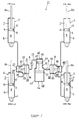
- the four-wheeled vehicle suspension device or system according to the first embodiment will be described in detail in reference to FIG. 1.
- FIG. 1 shows the constitution of an embodiment of the four-wheeled vehicle suspension.
- components that are the same as or similar to those described in reference to FIGs. 10 to 12 are provided with the same key numbers and their detailed descriptions are omitted.
- the four-wheeled vehicle suspension system 21 shown in FIG. 1 is constituted that the lower oil chamber 8 of the hydraulic cylinder 2 for the left front wheel is connected to the lower oil chamber 8 of the hydraulic cylinder 2 for the right front wheel through a pressure regulator 22, and the lower oil chamber 8 of the hydraulic cylinder 2 for the left rear wheel is connected to the lower oil chamber 8 of the hydraulic cylinder 2 for the right rear wheel through a first communication passage 23.
- the pressure regulator 22 comprises a first and a second pressure regulating cylinders 26 and 29, with the former having a first oil chamber 24 connected to the lower oil chamber 8 of the hydraulic cylinder 2 for the left front wheel and a first movable wall 25 for changing the volume of the first oil chamber 24, and with the latter having a second oil chamber 27 connected to the lower oil chamber 8 of the hydraulic cylinder 2 for the right front wheel and a second movable wall 28 for changing the volume of the second oil chamber 27 by interlocked motion with the first movable wall 25 so that the volumetric changes of the first and second oil chambers 24. and 27 are in agreement with each other.
- the first and the second pressure regulating cylinders 26 and 29 of this embodiment are formed as a single component so that the first and second movable walls 25 and 28 are located coaxially.
- the movable walls 25 and 28 of the pressure regulating cylinders 26 and 29 are formed so that the effective cross-sectional areas of the first and second oil chambers 24 and 27 are equal to each other and interconnected so that the volumes of the first and second oil chambers 24 and 27 are always equal to each other.
- mutual fluid communication between the hydraulic routes of the first and second oil chambers 24 and 27 is made through a throttle 30 bored in the second movable wall 28.
- the first pressure regulating cylinder 26 is formed with a pressure regulating oil chamber 31 the volume of which is changed by the movement of the first and second movable walls 25 and 28.
- the pressure regulating oil chamber 31 is made to communicate with a first communication passage 23, interconnecting the lower oil chambers 8 of the two hydraulic cylinders 2 for the rear wheels, through a throttle 32 and a second communication passage 33.
- the second communication passage 33 is connected to a flow rate regulator 34.
- the flow rate regulator 34 comprises a single cylinder 39 the interior of which is dived with a movable wall 37 into an oil chamber 36 connected through a throttle 35 to the second passage 33 and a high pressure gas chamber 38.
- the cylinder 39 corresponds to the flow rate regulating cylinder.
- the high pressure gas chamber 38 is filled with a high pressure gas. As the movable wall 37 moves right and left as seen in FIG. 1, working oil flows through the throttle 35.
- damping forces are produced as working oil flows through a throttle 10 bored in the piston 6 of each hydraulic cylinder 2 and as working oil flows through the throttle 30 of the pressure regulator 22.
- the damping force is produced with the pressure regulator 22 because the increase in the oil pressure in the first oil chamber 24 and the decrease in the oil pressure in the second oil chamber 27, in the state of the first and second movable walls 25 and 28 of the pressure regulator 22 remaining motionless, cause working oil to flow through the throttle 30.
- the first and the second movable walls 25 and 28 remain motionless because working oil flows from the hydraulic cylinder 2 for the left rear wheel to the hydraulic cylinder 2 for the right rear wheel, and working oil does not flow into or out of the pressure regulating chamber 31.
- a similar phenomenon also occurs when a hydraulic cylinder 2 on the opposite, right or left side makes an action different from the action during rolling, namely when the hydraulic cylinder 2 that extends during rolling is compressed as affected with the road surface irregularities.
- the damping force is produced as working oil flows from the second communication passage 33 through the throttle 35 into the oil chamber 36 of the flow rate regulator 34.
- the damping force produced as working oil passes through the throttle 35 stabilizes the damping force that restricts the rolling of the vehicle.
- the first communication passage 23 interconnecting the lower oil chambers 8, 8 of the hydraulic cylinders 2, 2 for the left and right rear wheels through the throttle 32 to the second communication passage 33 on the side of the flow rate regulator 34. Therefore, a damping force is produced as working oil flows into or out of the second communication passage 33, and the behavior of the vehicle body during rolling is all the more stabilized.
- a throttle may be disposed at the position indicated with the symbol A in FIG. 1, namely in the middle of the second communication passage 33 between the pressure regulating oil chamber 31 of the pressure regulator 22 and the flow rate regulator 34. Providing this throttle makes it possible to increase the damping force during pitching and bouncing.
- the position of the flow rate regulator 34 is not limited to that shown in FIG. 1 but may be connected to the middle of the first communication passage 23.
- This embodiment is an example in which the two hydraulic cylinders 2 on the front wheel side are respectively connected to the pressure regulator 22. However, it may also be constituted in reversed front-rear relation, with the hydraulic cylinder 2 for the left rear wheel and the hydraulic cylinder 2 for the right rear wheel interconnected through the pressure regulator 22, and with the two hydraulic cylinders 2 on the front wheel side interconnected.
- Employing this constitution makes it possible to produce a damping force against the vertical movement of the front part of the vehicle body with the throttle 32 interposed between the first and second communication passages 23 and 33. This makes it possible to prevent damping forces from becoming short even if the sprung weight on the front wheel side is relatively great.
- the throttle 32 interposed between the first and second communication passages 23 and 33 can be omitted, presence of the throttle 32 increases the damping force when the two hydraulic cylinders 2 on the rear wheel side work in the same direction, the damping force is prevented from becoming short when a heavy object is loaded on a deck (not shown) on the rear wheel side.
- the four-wheeled vehicle suspension device or system according to the second embodiment will be described in detail in reference to FIG. 2.
- FIG. 2 shows the constitution of the four-wheeled vehicle suspension system of the second embodiment.
- components that are the same as or similar to those described in reference to FIGs. 10 to 12 are provided with the same symbols or key numbers and their detailed descriptions are omitted.
- the constitution of the four-wheeled vehicle suspension system 21 shown FIG. 2 is the same as that of the first embodiment except for the constitution of the flow rate regulator and the direct connection of the first communication passages 23 to the second communication passage 33.
- the flow rate regulator 34 of this embodiment comprises; a third pressure regulating cylinder 43 and a fourth pressure regulating cylinder 46, with the cylinder 43 having a third oil chamber 41 communicating with the pressure regulating oil chamber 31 of the pressure regulator 22 and a third movable wall 42 for changing the volume of the third oil chamber 41, with the cylinder 46 having a fourth oil chamber 44 communicating with the first communication passage 23 and a fourth movable wall 45 for changing the volume of the fourth oil chamber 44 by the interlocked motion with the third movable wall 42 so that the volumetric changes of the third and the fourth oil chambers 41 and 44 are in mutual agreement.
- the third and the fourth pressure regulating cylinders 43 and 46 are formed in a single body so that the third and the fourth movable walls 42 and 45 are located coaxially.
- the third and the fourth movable walls 42 and 45 are formed so that the effective cross-sectional areas of the third and the fourth oil chambers 41 and 44 are in mutual agreement, and that they are interconnected so that the volumes of the third and the fourth oil chambers 41 and 44 are always in mutual agreement.
- the hydraulic routes of the third and fourth oil chambers 41 and 44 are made to communicate with each other through a throttle 47 provided in the fourth movable wall 45.
- a high pressure gas chamber 48 defined with the third movable wall 42 is formed integrally with the third pressure regulating cylinder 43.
- the high pressure gas chamber 48 is filled with a gas to a high pressure.
- Working oil flows through the throttle 47 bored in the fourth movable wall 45 as the third and the fourth movable walls 42 and 45 move right or left as seen in FIG. 1.
- a throttle is not provided between the first communication passage 23, interconnecting the hydraulic cylinders 2, 2 for the right and left rear wheels, and the second communication passage 33.
- a throttle may be provided at a position indicated with the symbol A in FIG. 2, namely at a position in the middle of the second communication passage 33 between the pressure regulating oil chamber 31 of the pressure regulator 22 and the third oil chamber 41 of the flow rate regulator 34. Providing this throttle makes it possible to increase the damping force during pitching and bouncing. Moreover, since the throttle produces a damping force against the vertical displacement of the front part of the vehicle, it is possible to prevent damping forces from becoming short even if the sprung weight on the front wheel side is relatively great.
- This embodiment is an example in which the two hydraulic cylinders 2 on the front wheel side are respectively connected to the pressure regulator 22. However, it may also be constituted in reversed front-rear relation, with the hydraulic cylinder 2 for the left rear wheel and the hydraulic cylinder 2 for the right rear wheel interconnected through the pressure regulator 22, and with the two hydraulic cylinders 2 on the front wheel side interconnected.
- the flow rate regulator 34 may be constituted as shown in FIG. 3.
- FIG. 3 shows the constitution of another embodiment of the flow rate regulator.
- components that are the same as or similar to those described in reference to FIG. 2 are provided with the same symbols and their detailed explanations are omitted.
- the flow rate regulator 34 shown in FIG. 3 employs a fifth oil chamber 49 in place of the high pressure gas chamber in the third pressure regulating cylinder 43.
- the fifth oil chamber 49 is made to communicate through a throttle 52 with the oil chamber 51 of a fifth pressure regulating cylinder 50 formed separately from the third pressure regulating cylinder 43.
- the fifth pressure regulating cylinder 50 is formed with a movable wall 53 defining the oil chamber 51 and a high pressure gas chamber 54.
- the high pressure gas chamber 54 is filled with a high pressure gas.
- the four-wheeled vehicle suspension device or system according to the third embodiment may be constituted as shown in FIG. 4.
- FIG. 4 shows another form of embodiment of the four-wheeled vehicle suspension system. Components that are the same as or similar to those described in reference to FIGs. 1, 2, 10, and 12 are provided with the same symbols and their detailed explanations are omitted.
- the constitution of the four-wheeled vehicle suspension system 21 shown in FIG. 4 is the same as that of the second embodiment except that a throttle 32 is interposed between the first communication passage 23 interconnecting the hydraulic cylinder 2 for the left rear wheel and the second communication passage 33 in which the flow rate regulator 34 is interposed.
- a throttle may be interposed at the position indicated with the symbol A, and the flow rate regulator 34 may be replaced with the one shown in FIG. 3.
- FIG. 5 shows another form of embodiment of the four-wheeled vehicle suspension system. Components that are the same as or similar to those described in reference to FIGs. 1, to 4, 10, and 12 are provided with the same symbols and their detailed explanations are omitted.
- the four-wheeled vehicle suspension system 21 shown in FIG. 5 is constituted like the first to the third embodiments with the hydraulic cylinders 2 for the right and left front wheels interconnected through the pressure regulator 22.
- the pressure regulator 22 is referred to as "the first pressure regulator" in the following description.
- the second pressure regulator 61 comprises; a third pressure regulating cylinder 64 having a third oil chamber 62 communicating with the lower oil chamber 8 of the hydraulic cylinder 2 for the left rear wheel and having a third movable wall 63 for changing the volume of the third oil chamber 62; a fourth pressure regulating cylinder 67 having a fourth movable wall 66 for changing the volume of the fourth oil chamber 65 in interlocked motion with the third movable wall 63 so that changes in the volumes of the third and fourth oil chambers 62 and 65 are mutually in agreement; a throttle 68 interposed between the hydraulic routes of the third and fourth oil chambers 62 and 65, and a pressure regulating oil chamber 69 the volume of which is changed as the third and fourth movable walls 63 and 66 move.
- the pressure regulating oil chamber 31 of the first pressure regulator 22 and the pressure regulating oil chamber 69 of the second pressure regulator 61 are interconnected through the second communication passage 33.
- the second communication passage 33 is connected to the flow rate regulator 34.
- the flow rate regulator 34 is constituted the same as in the first embodiment.
- the movable walls 63 and 66 are held immovable at this time, and the volume of the pressure regulating chamber 69 remains unchanged.
- the volumetric change of the hydraulic route due to the movement of the first and second movable walls 25 and 28 is offset by the movement of the movable wall 37 of the flow rate regulator 34. That is to say, a damping force is produced as working oil flows into or out through the throttle 35 of the flow rate regulator 34. This phenomenon occurs likewise when one of the hydraulic cylinders 2 for the rear wheels makes an action that is different from the action normally occurring during rolling of the vehicle.
- the damping force produced with the first or second pressure regulator 22 or 61 decreases on one hand when the vehicle negotiates an irregular road surface while the vehicle is rolling, on the other hand a damping force is produced with the flow rate regulator 34. In this way, the damping force for restricting rolling is stabilized.
- damping forces when the vehicle pitches are produced only with the throttles 10 provided in the pistons of the respective hydraulic cylinders 2. That is, the damping force during rolling is relatively reduced and the behavior of the vehicle becomes slow.
- the damping force during pitching is produced with both the throttles 10 provided in the pistons of the respective hydraulic cylinders 2 and the throttle 35 in the flow rate regulator 34.
- the pressure of high pressure gas in the flow rate regulator 34 works as a spring force.
- Another feature of this embodiment is that the first and second pressure regulator 22 and 61 can work independently of each other. Therefore, even in the case that the two hydraulic cylinder 2 for the front wheels behave like in a left turn and the two hydraulic cylinder 2 for the rear wheels behave like in a right turn, damping forces are also produced. Moreover, it is possible to set individually the damping force characteristics of the throttle 30 of the first pressure regulator 22 and the throttle 68 of the second pressure regulator 61.
- a throttle or throttles may be provided in the position A or B, or both positions A and B indicated in FIG. 5; the position A in the middle of the second communication passage 33 and between the pressure regulating chamber 31 of the first pressure regulator 22 and the flow rate regulator 34, and the position B in the middle of the second communication passage 33 and between the flow rate regulator 34 and the second pressure regulator 61.
- Providing the throttle or throttles in this way the damping force during pitching or bouncing can be increased.
- providing a throttle in the position A makes it possible to produce a damping force against the vertical movement of the front part of the vehicle and to prevent the damping force from becoming short even if the sprung weight on the front wheel side is relatively great.
- the damping force when the two hydraulic cylinders 2 on the rear wheel side move in the same direction can be increased by providing the throttle in the position B, the damping force is prevented from becoming short even when a heavy objected is loaded on a carrier deck (not shown) on the rear wheel side.
- Another constitution is also possible, in which two hydraulic cylinders on one, right or left side of the vehicle body are connected to the first pressure regulator 22, and the other two hydraulic cylinders are connected to the second pressure regulator 61.
- this constitution is employed, the same phenomenon as that occurring during rolling with the constitution shown in FIG. 5 occurs during pitching. That is, the decrease in the damping forces of the first and second pressure regulators 22 and 61 during pitching are offset with the damping force produced with the flow rate regulator 34.
- Another example of different constitution is that the hydraulic cylinders 2 for the left front and the right rear wheels are connected to the first pressure regulator 22, and the hydraulic cylinders 2 for the right front and the left rear wheels are connected to the second pressure regulator 61.
- the same phenomenon as that described above occurs when wheels as seen from the front move in a twisting direction of the vehicle body. That is, the decrease in the damping forces produced with the pressure regulators 22 and 61 is offset with the damping force produced with the flow rate regulator 34.
- the four-wheeled vehicle suspension device or system according to the fifth embodiment will be described in detail in reference to FIG. 6.
- FIG. 6 shows the constitution of the four-wheeled vehicle suspension system.
- components that are the same as or similar to those described in reference to FIGs. 1 to 5, 10 to 12 are provided with the same symbols and their detailed descriptions are omitted.
- the four-wheeled vehicle suspension system 21 shown in FIG. 6 is constituted like the fourth embodiment, with the two hydraulic cylinders 2 for the front wheels interconnected through the first pressure regulator 22, and with the two hydraulic cylinders 2 for the rear wheels interconnected through the second pressure regulator 61.
- a flow rate regulator 34 of the same constitution as that in the second embodiment is interposed in the second communication passage 33 which interconnects the pressure regulating oil chamber 31 of the first pressure regulator 22 and the pressure regulating oil chamber 69 of the second pressure regulator 61.
- the movable walls 63 and 66 are held immovable and the volume of the pressure regulating chamber 64 does not change. Therefore, the volumetric change in the hydraulic route with the movement of the movable walls 25 and 28 of the first pressure regulator 22 is offset with the volumetric change caused by the movement of the movable walls 42 and 45 of the flow rate regulator 34. That is, a damping force is produced as the working oil flows through the throttle 47 of the flow rate regulator 34 between the third oil chamber 41 and the fourth oil chamber 44. This phenomenon occurs likewise when one of the hydraulic cylinders 2 for the rear wheels move in the direction different from that expected when the vehicle rolls.
- the first and second pressure regulators 22 and 61 work independently, damping forces are produced even when the two hydraulic cylinders 2 for the front wheel work as expected during a left turn while the two hydraulic cylinders 2 for the rear wheel work as expected during a right turn.
- the throttle 30 of the first pressure regulator 22 may be set to have a different damping characteristic from that of the throttle 68 of the second pressure regulator 61.
- a throttle may be provided in the position A or B, or both positions A and B indicated in FIG. 6; the position A in the middle of the second communication passage 33 and between the pressure regulating chamber 31 of the first pressure regulator 22 and the flow rate regulator 34, and the position B in the middle of the second communication passage 33 and between the flow rate regulator 34 and the second pressure regulator 61.
- Providing the throttle(s) in this way the damping force during pitching or bouncing can be increased.
- providing a throttle in the position A makes it possible to produce a damping force against the vertical movement of the front part of the vehicle and to prevent the damping force from becoming short even if the sprung weight on the front wheel side is relatively great.
- the damping force when the two hydraulic cylinders 2 on the rear wheel side move in the same direction can be increased by providing the throttle in the position B, the damping force is prevented from becoming short even when a heavy objected is loaded on a carrier deck (not shown) on the rear wheel side.
- the flow rate regulator 34 may be replaced with the one shown in FIG. 3.
- the four-wheeled vehicle suspension device or system according to the sixth embodiment may be constituted as shown in FIG. 7.
- FIG. 7 shows the constitution of another embodiment of the four-wheeled vehicle suspension system.
- components that are the same as or similar to those described in reference to FlGs. 1 to 6, 10 to 12 are provided with the same symbols and their detailed descriptions are omitted.
- the four-wheeled vehicle suspension system 21 shown in FIG. 7 is constituted with the hydraulic cylinders 2 for the left front and left rear wheels interconnected through the first pressure regulator 22, and with the hydraulic cylinders 2 for the right front and right rear wheels interconnected through the second pressure regulator 61.
- a flow rate regulator 34 of the same constitution as in the second embodiment is interposed in the second communication passage 33 interconnecting the pressure regulating chamber 31 of the first pressure regulator 22 and the pressure regulating chamber 69 of the second pressure regulator 61.
- the first and second pressure regulators 22 and 61 work independently, damping forces are produced even when the two hydraulic cylinders 2 on the left side of the vehicle move in directions occurring when the vehicle nose-dives (with the front part of the vehicle moving down) and the two hydraulic cylinders 2 on the right side of the vehicle move in directions occurring when the vehicle makes a nose-up movement (with the rear part of the vehicle moving down), namely when the front wheels and the rear wheels as seen from the front move in directions in which the vehicle body is twisted. Moreover, it is possible to set individually the damping force characteristics of the throttle 30 of the first pressure regulator 22 and the throttle 68 of the second pressure regulator 61.
- the working oil flow rate through the throttle 47 in the flow rate regulator 34 corresponds to the inflow or outflow rate of the working oil to or from the front and rear two hydraulic cylinders on the right or left side. Therefore, the damping force during rolling can be increased in comparison with that during pitching or when the front and rear wheels as seen from the front move in the twisting directions. As a result, rolling can be sufficiently restricted even if throttles having the same damping characteristic are used for the first and second pressure regulators 22 and 61, and the flow rate regulator 34.
- a throttle may be provided in either one or both of the position indicated with the symbol A in FIG. 7, between the first pressure regulator 22 and the flow rate regulator 34, and the position indicated with the symbol B between the flow rate regulator 34 and the second pressure regulator 61. Providing the throttle or throttles in this way can increase the damping force during rolling or bouncing.
- the flow rate regulator may be replaced with the one shown in FIG. 3.
- the four-wheeled vehicle suspension device or system according to the seventh embodiment may be constituted as shown in FIG. 8.
- FIG. 8 shows the constitution of another embodiment of the four-wheeled vehicle suspension system.
- components that are the same as or similar to those described in reference to FIGs. 1 to 7, 10 to 12 are provided with the same symbols and their detailed descriptions are omitted.
- the four-wheeled vehicle suspension system 21 shown in FIG. 8 is constituted with the hydraulic cylinders 2 for the left front and right rear wheels interconnected through the first pressure regulator 22, and with the hydraulic cylinders 2 for the right front and left rear wheels interconnected through the second pressure regulator 61.
- a flow rate regulator 34 of the same constitution as in the second embodiment is interposed in the second communication passage 33 which interconnects the pressure regulating oil chamber 31 of the first pressure regulator 22 and the pressure regulating oil chamber 69 of the second pressure regulator 61.
- the movable walls 63 and 66 are held immovable and the volume of the pressure regulating chamber 69 does not change. Therefore, the volumetric change in the hydraulic route with the movement of the movable walls 25 and 28 of the first pressure regulator 22 is offset with the volumetric change due to the movement of the movable walls 42 and 45 of the flow rate regulator 34. That is, a damping force is produced as the working oil flows through the throttle 47 of the flow rate regulator 34 between the third and fourth oil chambers 41 and 44.
- damping forces are produced with both the throttles 10 provided in the pistons of the respective hydraulic cylinders 2 and the throttles 30 and 68 of the first and second pressure regulators 22 and 61.
- the damping force is produced only with the throttles 10 provided in the pistons 6 of the respective hydraulic cylinders 2.
- the pressure of high pressure gas in the flow rate regulator 34 works as a spring force.
- damping characteristics of the throttles 30 and 68 of the first and second pressure regulators 22 and 61 may be set individually.
- a throttle or throttles may be provided in either one or both of the positions indicated with the symbol A in FIG. 8, between the first pressure regulator 22 and the flow rate regulator 34, and with the symbol B between the flow rate regulator 34 and the second pressure regulator 61. Providing the throttle or throttles in this way can increase the damping force when the front and rear wheels move in the twisting directions as seen from the front.
- the flow rate regulator may be replaced with the one shown in FIG. 3.
- the flow rate regulator 34 used here may be the one shown in FIGs. 1 or 5.
- the pressure regulators 22 and 61 used in the above embodiments may be constituted as shown in FIG. 9 as another embodiment, and comprises a first pressure regulating cylinder 72 with a movable wall 73 inside of which is formed a second pressure regulating cylinder 74, with a throttle 75 formed in a wall 74a of the second pressure regulating cylinder 74.
- the symbol 76 denotes a first oil chamber, 77 a second oil chamber, and 78 a pressure regulating oil chamber.
- the symbol A1 represents the effective cross-sectional area of the first pressure regulating cylinder 72, and A2 that of the second pressure regulating cylinder 74.
- the four hydraulic cylinders 2 may be constituted either with hydraulic dampers or may be formed separately from the hydraulic dampers and interposed between the wheels and the vehicle body.
- the hydraulic cylinders 2 are constituted separately from the hydraulic dampers in this way, a simple through hole instead of the throttle 10 is bored in each piston 6.
- the four-wheeled vehicle suspension device comprises hydraulic cylinders 2, each provided for each wheel, with the piston 6 of each hydraulic cylinder 2 connected to one of vehicle body and wheel sides and with the cylinder body 5 of each hydraulic cylinder 2 connected to the other of the vehicle body and wheel sides, with the oil chambers 8 of the two hydraulic cylinders 2 located on the same front or rear side of the vehicle body interconnected through a pressure regulator 22, with the pressure regulator 22 comprising; a first pressure regulating cylinder 26 having a first oil chamber 24 connected to the oil chamber 8 of one hydraulic cylinder 2 and also having a first movable wall 22 for changing the volume of the first oil chamber 24, a second pressure regulating cylinder 29 having a second oil chamber 27 connected to the oil chamber 8 of the other hydraulic cylinder 2 and also having a second movable wall 28 for changing the volume of the second oil chamber 27 in interlocked motion with the first movable wall 25 so that the volumetric changes of the first and second oil chambers 24,27 are in mutual agreement, and a throttle 30 interposed
- a four-wheeled vehicle suspension system may be materialized with which the damping force during rolling of a vehicle is not affected with road surface irregularities.
- a damping force is produced as working oil flows through the throttle of the pressure regulator when the vehicle body rolls.
- the movable wall of the pressure regulator moves to change the volume of the pressure regulating oil chamber of the pressure regulator.
- working oil flows into or out of the flow rate regulating cylinder through the throttle.
- the other two hydraulic cylinders during rolling make a different movement from that normally occurring during rolling, with both of the hydraulic cylinders moving in the same direction, working oil flows into or out of the flow rate regulating cylinder through the throttle.
- the four-wheeled vehicle suspension system comprises hydraulic cylinders 2, each provided for each wheel, with the oil chambers 8 of the two hydraulic cylinders 2 located on the same front or rear side of the vehicle body interconnected through a pressure regulator 22, with the pressure regulator 22 comprising; a first pressure regulating cylinder 26 having a first oil chamber 24 connected to the oil chamber 8 of one hydraulic cylinder 2 and also having a first movable wall 25 for changing the volume of the first oil chamber 24, a second pressure regulating cylinder 29 having a second oil chamber 27 connected to the oil chamber 8 of the other hydraulic cylinder 2 and also having a second movable wall 28 for changing the volume of the second oil chamber 29 in interlocked motion with the first movable wall 25 so that the volumetric changes of the first and second oil chambers 24,27 are in mutual agreement, and a throttle 30 interposed between the hydraulic routes of the first and second oil chambers 24,27, with the pressure regulator 22 provided with a pressure regulating oil chamber 31 the volume of which is changed by the movement of
- a four-wheeled vehicle suspension system may be materialized with which the damping force during rolling of a vehicle is not affected with road surface irregularities.
- a damping force is produced when a vehicle body rolls as working oil flows through the throttle of the pressure regulator.
- the movable wall of the pressure regulator moves to change the volume of the pressure regulating oil chamber of the pressure regulator, and working oil flows into or out of the third oil chamber of the flow rate regulating cylinder.
- the four-wheeled vehicle suspension system comprising hydraulic cylinders 2 in two pairs for a vehicle body, with each cylinder allocated to each wheel, with one pair of hydraulic cylinders interconnected through a first pressure regulator 22, with the first pressure regulator 22 comprising; a first pressure regulating cylinder 26 having a first oil chamber 24 connected to the oil chamber 8 of one hydraulic cylinder 2 and also having a first movable wall 25 for changing the volume of the first oil chamber 24, a second pressure regulating cylinder 29 having a second oil chamber 27 connected to the oil chamber 8 of the other hydraulic cylinder 2 and also having a second movable wall 28 for changing the volume of the second oil chamber 29 in interlocked motion with the first movable wall 25 so that the volumetric changes of the first and second oil chambers 24,27 are in mutual agreement, and a throttle 30 interposed between the hydraulic routes of the first and second oil chambers, with the other pair of hydraulic cylinders 2 interconnected through a second pressure regulator 61, with the second pressure regulator 61 comprising; a first pressure regulating cylinder 26 having
- the first and second pressure regulators produce damping forces when two hydraulic cylinders for respective pressure regulators move in mutually different directions. Under the condition of the movable walls of the pressure regulators immovable, there is no working oil flow between the pressure regulating oil chambers of the two pressure regulators. However, when one of the four hydraulic cylinders moves in an opposite direction, the movable wall of the pressure regulator connected to the hydraulic cylinder moves, and working oil flows into or out of the pressure regulating oil chamber. At this time, since working oil does not flow into or out of the pressure regulating chamber of the other pressure regulator, a damping force is produced as working oil flows into or out of the flow rate regulating cylinder through the throttle.
- a four-wheeled vehicle suspension system can be materialized with which the damping force during rolling or pitching is not affected with irregular road surfaces.
- a damping force is produced when two hydraulic cylinders for each of the first and second pressure regulators move in mutually opposite directions.
- Working oil does not move between the pressure regulating oil chambers of the two pressure regulators under the condition of the movable walls of the pressure regulators remaining motionless.
- the movable wall of the pressure regulator connected to the hydraulic cylinder moves, and working oil flows into or out of the pressure regulating oil chamber.
- working oil flows into or out of the flow rate regulating cylinder through the throttle to produce a damping force.
- the decrease in the damping force produced with the pressure regulator is offset with the damping force produced with the flow rate regulating cylinder.
- the movable wall of the second pressure regulator at this time is held immovable and the volume of the pressure regulating oil chamber does not change. Therefore, the volumetric change of the hydraulic route due to the movement of the movable wall of the first pressure regulator is offset with that due to the movement of the movable wall of the flow rate regulating cylinder. That is to say, a damping force is produced as working oil flows into or out through the throttle of the flow rate regulation cylinder. The above phenomenon also occurs even when the hydraulic cylinder that makes a different movement from the movement normally occurring during rolling is located on a different, front or rear side.
- the four-wheeled vehicle suspension system comprising hydraulic cylinders 2 in two pairs for a vehicle body, with each cylinder allocated to each wheel, with one pair of hydraulic cylinders 2 interconnected through a first pressure regulator 22, with the first pressure regulator 22 comprising; a first pressure regulating cylinder 26 having a first oil chamber 24 connected to the oil chamber 8 of one hydraulic cylinder 2 and also having a first movable wall 25 for changing the volume of the first oil chamber 24, a second pressure regulating cylinder 29 having a second oil chamber 27 connected to the oil chamber 8 of the other hydraulic cylinder 2 and also having a second movable wall 28 for changing the volume of the second oil chamber 27 in interlocked motion with the first movable wall 25 so that the volumetric changes of the first and second oil chambers 24,27 are in mutual agreement, and a throttle 30 interposed between the hydraulic routes of the first and second oil chambers 24,27, with the other pair of hydraulic cylinders 2 interconnected through a second pressure regulator 61, with the second pressure regulator
- damping forces are produced when the vehicle body rolls as working oil flows through the throttles of the first and second pressure regulators.
- the movable wall of the pressure regulator to which the hydraulic cylinder is connected moves.
- a differential pressure is produced between the fifth and sixth oil chambers of the flow rate regulating cylinder, and working oil flows through the throttle provided between the oil chambers.
- a damping force is produced to offset the decrease in the damping force on the pressure regulator side.
- both of the movable walls of the first and second pressure regulators move to produce a differential pressure between the third and fourth oil chambers of the flow rate regulating cylinder connected to the pressure regulating oil chambers of both of the pressure regulators.
- the damping force against rolling is produced as working oil flows through the throttle between the third and fourth oil chambers.
- the four-wheeled vehicle suspension device comprises a hydraulic cylinder 2 for each wheel.
- Said hydraulic cylinders 2 are provided in two pairs, wherein at least a first pair of said hydraulic cylinders 2 is interconnected through a pressure regulator 22, and a second pair of hydraulic cylinders 2 is interconnected with each other and connected with said pressure regulator 22 by a communication passage means 23,33.
- a flow rate regulator 34 is provided between said pressure regulator 22 and said second pair of hydraulic cylinders 2.
- Said pressure regulator 22 comprises: a first pressure regulating cylinder 26 having a first oil chamber 24 connected to one hydraulic cylinder 2 of the first pair and also having a first movable wall 25 for changing a volume of the first oil chamber 24; a second pressure regulating cylinder 29 having a second oil chamber 27 connected to the other hydraulic cylinder 2 of the first pair and also having a second movable wall 28 for changing the volume of the second oil chamber 27 in interlocked motion with the first movable wall 25, wherein volumetric changes of the first and second oil chambers 24,27 are in mutual agreement; a throttle 30 interposed between the first and second oil chambers 24,27.
- Said pressure regulator 22 further comprises: a pressure regulating oil chamber 31 a volume of which is changeable by the movement of the first and second movable walls 25,28.
- Said pressure regulating oil chamber 31 is connected to the hydraulic cylinders 2 of the second pair by said communication passage means 23,33. Said pressure regulating oil chamber 31 is connected to the flow rate regulator 34.
- said flow rate regulator 34 comprises a flow rate regulating cylinder divided with the movable wall 37 into a high pressure gas chamber 38 and an oil chamber 36.
- a throttle 35 is provided between said oil chamber 36 and said communication passage means 23,33 for working oil to flow through by the movement of the movable walls of the flow rate regulating cylinder.
- said flow rate regulator 34 comprises a flow rate regulating cylinder having a third pressure regulating cylinder 43 with a third movable wall 42 for changing a volume of the third oil chamber 41, a fourth pressure regulating cylinder 46 having a fourth oil chamber 44 connected to the second pair of hydraulic cylinders 2 and also having a fourth movable wall 45 for changing the volume of the fourth oil chamber 44 in interlocked motion with the third movable wall 42 so that volumetric changes of the third and fourth oil chambers 41,44 are in mutual agreement, a high pressure gas chamber 48 filled with a high pressure gas for urging the third and fourth movable walls 42,45 toward the oil chambers, and a throttle 47 interposed between hydraulic routes of the third and fourth oil chambers 41,44.
- said flow rate regulator 34 comprises a flow rate regulating cylinder having a third pressure regulating cylinder 43 with a third movable wall 42 for changing a volume of the third oil chamber 41, a fourth pressure regulating cylinder 46 having a fourth oil chamber 44 connected to the second pair of hydraulic cylinders 2 and also having a fourth movable wall 45 for changing the volume of the fourth oil chamber 44 in interlocked motion with the third movable wall 42 so that volumetric changes of the third and fourth oil chambers 41,44 are in mutual agreement, a third movable wall 42 within the third pressure regulating cylinder 43 also defines a fifth oil chamber 49 which communicates through a throttle 52 with an oil chamber 51 of a fifth pressure regulating cylinder 50 provided with a fifth moveable wall 53 and high pressure gas chamber 54 filled with a high pressure gas for urging the third, fourth and fifth movable walls 42,45,53 toward the oil chambers, and a throttle 47 interposed between hydraulic routes of the third and fourth oil chambers 41,44.
- the second pair of hydraulic cylinders 2 is interconnected by a first communication passage 23 and a throttle 32 is provided between said first communication passage 23 and said flow rate regulator 34.
- said pressure regulator connecting the first pair of hydraulic cylinders 2 is a first pressure regulator 22 and the second pair of hydraulic cylinders 2 is interconnected through a second pressure regulator 61.
- Said second pressure regulator 61 comprises a third pressure regulating cylinder 64 having a third oil chamber 62 connected to one hydraulic cylinder 2 of the second pair and also having a third movable wall 63 for changing the volume of the third oil chamber 62, a fourth pressure regulating cylinder 67 having a fourth oil chamber 65 connected to the other hydraulic cylinder 2 of the second pair and also having a fourth movable wall 66 for changing the volume of the fourth oil chamber 65 in interlocked motion with the third movable wall 63 so that the volumetric changes of the third and fourth oil chambers 62,65 are in mutual agreement, and a throttle 68 interposed between the hydraulic routes of the third and fourth oil chambers 62,65.
- the first and second pressure regulators 22,61 are respectively provided with pressure regulating oil chambers 31,69, with the pressure regulating oil chambers 31,69 interconnected, and with their volumes changed by the movement of movable walls 25,28,63,66 of the pressure regulators 22,61.
- At least one throttle A,B is provided between the first and second pressure regulator 22,61.
- the first pair of hydraulic cylinders 2 interconnected through a pressure regulator 22 are located on the same front or rear side of the vehicle body.
- the first pair of hydraulic cylinders 2 interconnected through a pressure regulator 22 are located on the same left or right side of the vehicle body.
- the first pair of hydraulic cylinders 2 interconnected through a pressure regulator 22 are located on opposing sides regarding a front and rear side and left and right side of the vehicle body to constitute a cross connection of the hydraulic cylinders 2.
- each hydraulic cylinder 2 comprises a piston 6 connected to one of vehicle body and wheel sides and a cylinder body 5 connected to the other of the vehicle body and wheel sides, and each hydraulic cylinder 2 comprises an oil chamber 8, wherein said oil chambers 8 of the hydraulic cylinders 22 is connected with the respective pressure regulator or flow rate regulator.
Landscapes
- Engineering & Computer Science (AREA)
- Mechanical Engineering (AREA)
- General Engineering & Computer Science (AREA)
- Vehicle Body Suspensions (AREA)
- Automatic Cycles, And Cycles In General (AREA)
Abstract
Description
- This invention relates to a suspension system for use in four-wheeled automobiles.
- An example of a type of suspension device or system for use in four-wheeled vehicles is disclosed in a publication, a Japanese laid-open patent application No. Hei-6-72127. The prior-art suspension system for use in four-wheeled vehicles disclosed in the above publication will be described in reference to FIGs. 10 to 12.
- These figures show a prior-
art suspension system 1 for use in four-wheeled vehicles. Thesuspension system 1 comprises fourhydraulic cylinders 2, each provided for each wheel, apressure regulator 3 and athrottle 4 both connected to the hydraulic routes of thehydraulic cylinders 2. - The four
hydraulic cylinders 2 are of an identical constitution, with each cylinder comprising acylinder body 5 with its interior defined with apiston 6 into anupper oil chamber 7 and alower oil chamber 8. Thepiston 6 is bored with acommunication passage 9 making fluid communication between the upper and thelower oil chambers throttle 10. - The lower end of the
cylinder body 5 of thehydraulic cylinder 2 is pivoted to a part that moves up and down together with wheel suspension links (not shown), while the upper part of apiston rod 6a of thehydraulic cylinder 2 is connected to part of a vehicle body (not shown). - The
pressure regulator 3 comprises a plural number ofpressure regulating cylinders 13, each having anoil chamber 11 and amovable wall 12 for changing the volume of theoil chamber 11. Themovable walls 12 of thepressure regulating cylinders 13 are formed so that their effective cross-sectional areas are the same each other, and interconnected so that the volumes of theoil chambers 11 are always the same each other. Theoil chambers 11 of thepressure regulating cylinders 13 are interconnected through thethrottle 4. Thepressure regulator 3 is constituted to have agas chamber 14 separated from theoil chambers 11 by means of themovable wall 12, so that themovable wall 12 is constantly forced toward theoil chamber 11 side. - The
pressure regulator 3 shown in FIG. 10 comprises twopressure regulating cylinders 13, with thelower oil chambers hydraulic cylinders oil chamber 11 of onepressure regulating cylinder 13, while thelower oil chambers hydraulic cylinders oil chamber 11 of the otherpressure regulating cylinder 13. Thepressure regulator 3 shown in FIG. 11 is arranged with one of the twopressure regulating cylinders 13 connected to thehydraulic cylinder 2 for the left front wheel and to thehydraulic cylinder 2 for the right rear wheel, and with the other of the twopressure regulating cylinders 13 connected to thehydraulic cylinder 2 for the right front wheel and to thehydraulic cylinder 2 for the left rear wheel. With thepressure regulator 3 shown in FIG. 12,pressure regulating cylinders 13 are allocated to the respectivehydraulic cylinders 2, with themovable walls 12 in the respectivepressure regulating cylinders 13 interconnected as a single body for interlocked movement. - With the
suspension system 1 shown in FIG. 10, when the vehicle body sways laterally, or rolls, working oil in theoil chamber 11 of onepressure regulating cylinder 13 flows through thethrottle 4 to theoil chamber 11 of the otherpressure regulating cylinder 13. Therefore, when the vehicle body rolls, damping forces are produced as working oil flows through thethrottles 10 of respectivehydraulic cylinders 2 and through thethrottle 4 of thepressure regulator 3. The damping force produced as working oil flows through thethrottle 4 when the vehicle body pitches becomes relatively small. - With the
suspension system 1 shown in FIG. 11, when the wheels as seen from the front move in a twisting direction of the vehicle body, working oil flows through thethrottle 4 of thepressure regulator 3 to produce a damping force. The damping force produced as working oil flows through thethrottle 4 when the vehicle body with thissuspension system 1 pitches also becomes relatively small. - With the
suspension system 1 shown in FIG. 12, when the vehicle body rolls, a differential oil pressure is produced between the two of the fourpressure regulating cylinders 13 on the left side and the other two on the right side. The working oil flows through the threethrottles 4 to offset the differential oil pressure, and thepressure regulator 3 produces a damping force. With thissuspension system 1, when the vehicle body pitches, a damping force is produced as relatively greater amount of working oil flows through the twothrottles 4 located on both sides. - However, the
conventional suspension system 1 for four-wheeled vehicles described above has problems: When the twohydraulic cylinders - For example with the
suspension system 1 shown in FIG. 10, when one of the twohydraulic cylinders pressure regulating cylinder 13 to that on the right side), the oil pressure in the hydraulic route connected to thehydraulic cylinder 2 decreases, and the amount of working oil flowing through thethrottle 4 located between thepressure regulating cylinders - With the
suspension system 1 shown in FIG. 11, although little working oil flows through thethrottle 4 of thepressure regulator 3 when the vehicle body rolls, increase or decrease in the oil pressure in one of thepressure regulating cylinders 13 when the vehicle body rolls causes working oil to flow through thethrottle 4 of thepressure regulator 3 to produce a damping force. In this case, the tilt of the vehicle body during rolling is temporarily restrained and gives a passenger an uncomfortable sense of incongruity. - With the
suspension system 1 shown in FIG. 12, when any one of the hydraulic cylinders moves in the direction opposite to that expected during rolling, the amount of working oil flowing through the central one of the threethrottles 4 decreases, and the damping force decreases undesirably. When one of the hydraulic cylinders works in the direction opposite to that expected during pitching, the amount of working oil flowing through thethrottle 4 in the center increases and, like the above description, the damping force decreases undesirably. - It is an objective of the present invention to provide four-wheeled vehicle suspension device having an damping force characteristic.
- According to the present invention said objective is solved by a four-wheeled vehicle suspension device comprises a hydraulic cylinder for each wheel, said hydraulic cylinders are provided in two pairs, wherein at least a first pair of said hydraulic cylinders is interconnected through a pressure regulator, and a second pair of hydraulic cylinders is interconnected with each other and connected with said pressure regulator by a communication passage means, wherein a flow rate regulator is provided between said pressure regulator and said second pair of hydraulic cylinders.
- Preferably, said pressure regulator comprises: a first pressure regulating cylinder having a first oil chamber connected to one hydraulic cylinder of the first pair and also having a first movable wall for changing a volume of the first oil chamber; a second pressure regulating cylinder having a second oil chamber connected to the other hydraulic cylinder of the first pair and also having a second movable wall for changing the volume of the second oil chamber in interlocked motion with the first movable wall, wherein volumetric changes of the first and second oil chambers are in mutual agreement; a throttle interposed between the first and second oil chambers.
- Preferably, said pressure regulator further comprises: a pressure regulating oil chamber a volume of which is changeable by the movement of the first and second movable walls.
- Preferably, said pressure regulating oil chamber is connected to the hydraulic cylinders of the second pair by said communication passage means.
- Preferably, said pressure regulating oil chamber is connected to the flow rate regulator.
- According to a preferred embodiment said flow rate regulator comprises a flow rate regulating cylinder divided with the movable wall into a high pressure gas chamber and an oil chamber, wherein a throttle is provided between said oil chamber and said communication passage means for working oil to flow through by the movement of the movable walls of the flow rate regulating cylinder.
- According to an other preferred embodiment said flow rate regulator comprises a flow rate regulating cylinder having a third pressure regulating cylinder with a third movable wall for changing a volume of the third oil chamber, a fourth pressure regulating cylinder having a fourth oil chamber connected to the second pair of hydraulic cylinders and also having a fourth movable wall for changing the volume of the fourth oil chamber in interlocked motion with the third movable wall so that volumetric changes of the third and fourth oil chambers are in mutual agreement, a high pressure gas chamber filled with a high pressure gas for urging the third and fourth movable walls toward the oil chambers, and a throttle interposed between hydraulic routes of the third and fourth oil chambers.
- According to a further preferred embodiment said flow rate regulator comprises a flow rate regulating cylinder having a third pressure regulating cylinder with a third movable wall for changing a volume of the third oil chamber, a fourth pressure regulating cylinder having a fourth oil chamber connected to the second pair of hydraulic cylinders and also having a fourth movable wall for changing the volume of the fourth oil chamber in interlocked motion with the third movable wall so that volumetric changes of the third and fourth oil chambers are in mutual agreement, a third movable wall within the third pressure regulating cylinder also defines a fifth oil chamber which communicates through a throttle with an oil chamber of a fifth pressure regulating cylinder provided with a fifth moveable wall and high pressure gas chamber filled with a high pressure gas for urging the third, fourth and fifth movable walls toward the oil chambers, and a throttle interposed between hydraulic routes of the third and fourth oil chambers.
- Preferably, the second pair of hydraulic cylinders is interconnected by a first communication passage and a throttle is provided between said first communication passage and said flow rate regulator.
- According to a preferred embodiment said pressure regulator connecting the first pair of hydraulic cylinders is a first pressure regulator and the second pair of hydraulic cylinders is interconnected through a second pressure regulator.
- Preferably, said second pressure regulator comprises a third pressure regulating cylinder having a third oil chamber connected to one hydraulic cylinder of the second pair and also having a third movable wall for changing the volume of the third oil chamber, a fourth pressure regulating cylinder having a fourth oil chamber connected to the other hydraulic cylinder of the second pair and also having a fourth movable wall for changing the volume of the fourth oil chamber in interlocked motion with the third movable wall so that the volumetric changes of the third and fourth oil chambers are in mutual agreement, and a throttle interposed between the hydraulic routes of the third and fourth oil chambers.
- Preferably, the first and second pressure regulators are respectively provided with pressure regulating oil chambers, with the pressure regulating oil chambers interconnected, and with their volumes changed by the movement of movable walls of the pressure regulators.
- Preferably at least one throttle is provided between the first and second pressure regulator.
- According to a preferred embodiment the first pair of hydraulic cylinders interconnected through a pressure regulator are located on the same front or rear side of the vehicle body.
- According to an other preferred embodiment the first pair of hydraulic cylinders interconnected through a pressure regulator are located on the same left or right side of the vehicle body.
- According to a further preferred embodiment the first pair of hydraulic cylinders interconnected through a pressure regulator are located on opposing sides regarding a front and rear side and left and right side of the vehicle body to constitute a cross connection of the hydraulic cylinders.
- According to the embodiments each hydraulic cylinder comprises a piston connected to one of vehicle body and wheel sides and a cylinder body connected to the other of the vehicle body and wheel sides, and each hydraulic cylinder comprises an oil chamber, wherein said oil chambers of the hydraulic cylinders is connected with the respective pressure regulator or flow rate regulator.
- In the following, the present invention is explained in greater detail with respect to several embodiments thereof in conjunction with the accompanying drawings, wherein:
- FIG. 1 shows the constitution of a four-wheeled vehicle suspension device as a first embodiment;
- FIG. 2 shows the constitution of a four-wheeled vehicle suspension device as a second embodiment;
- FIG. 3 shows a different embodiment of a flow rate regulator;
- FIG. 4 shows the constitution of a four-wheeled vehicle suspension device as another (third) embodiment;
- FIG. 5 shows the constitution of a four-wheeled vehicle suspension device as a fourth embodiment;
- FIG. 6 shows the constitution of a four-wheeled vehicle suspension device as a fifth embodiment;
- FIG. 7 shows the constitution of a four-wheeled vehicle suspension device as another (sixth) embodiment;
- FIG. 8 shows the constitution of a four-wheeled vehicle suspension device as another (seventh) embodiment;
- FIG. 9 shows another embodiment of a flow rate regulator;
- FIG. 10 is a cross-sectional view of a conventional four-wheeled vehicle suspension device;
- FIG. 11 is a cross-sectional view of a conventional four-wheeled vehicle suspension device; and
- FIG. 12 is a cross-sectional view of a conventional four-wheeled vehicle suspension device.
-
- The four-wheeled vehicle suspension device or system according to the first embodiment will be described in detail in reference to FIG. 1.
- FIG. 1 shows the constitution of an embodiment of the four-wheeled vehicle suspension. In the figure, components that are the same as or similar to those described in reference to FIGs. 10 to 12 are provided with the same key numbers and their detailed descriptions are omitted.
- The four-wheeled
vehicle suspension system 21 shown in FIG. 1 is constituted that thelower oil chamber 8 of thehydraulic cylinder 2 for the left front wheel is connected to thelower oil chamber 8 of thehydraulic cylinder 2 for the right front wheel through apressure regulator 22, and thelower oil chamber 8 of thehydraulic cylinder 2 for the left rear wheel is connected to thelower oil chamber 8 of thehydraulic cylinder 2 for the right rear wheel through afirst communication passage 23. - The
pressure regulator 22 comprises a first and a secondpressure regulating cylinders first oil chamber 24 connected to thelower oil chamber 8 of thehydraulic cylinder 2 for the left front wheel and a firstmovable wall 25 for changing the volume of thefirst oil chamber 24, and with the latter having asecond oil chamber 27 connected to thelower oil chamber 8 of thehydraulic cylinder 2 for the right front wheel and a secondmovable wall 28 for changing the volume of thesecond oil chamber 27 by interlocked motion with the firstmovable wall 25 so that the volumetric changes of the first andsecond oil chambers 24. and 27 are in agreement with each other. The first and the secondpressure regulating cylinders movable walls movable walls pressure regulating cylinders second oil chambers second oil chambers second oil chambers throttle 30 bored in the secondmovable wall 28. - The first
pressure regulating cylinder 26 is formed with a pressure regulatingoil chamber 31 the volume of which is changed by the movement of the first and secondmovable walls oil chamber 31 is made to communicate with afirst communication passage 23, interconnecting thelower oil chambers 8 of the twohydraulic cylinders 2 for the rear wheels, through athrottle 32 and asecond communication passage 33. - The
second communication passage 33 is connected to aflow rate regulator 34. Theflow rate regulator 34 comprises asingle cylinder 39 the interior of which is dived with amovable wall 37 into anoil chamber 36 connected through athrottle 35 to thesecond passage 33 and a highpressure gas chamber 38. Thecylinder 39 corresponds to the flow rate regulating cylinder. The highpressure gas chamber 38 is filled with a high pressure gas. As themovable wall 37 moves right and left as seen in FIG. 1, working oil flows through thethrottle 35. - With the four-wheeled
vehicle suspension system 21 constituted as shown in FIG. 1, for example when the vehicle body rolls so that thehydraulic cylinders hydraulic cylinders throttle 10 bored in thepiston 6 of eachhydraulic cylinder 2 and as working oil flows through thethrottle 30 of thepressure regulator 22. The damping force is produced with thepressure regulator 22 because the increase in the oil pressure in thefirst oil chamber 24 and the decrease in the oil pressure in thesecond oil chamber 27, in the state of the first and secondmovable walls pressure regulator 22 remaining motionless, cause working oil to flow through thethrottle 30. The first and the secondmovable walls hydraulic cylinder 2 for the left rear wheel to thehydraulic cylinder 2 for the right rear wheel, and working oil does not flow into or out of thepressure regulating chamber 31. - When for example the left front wheel enters a recess on the road surface during the above-described rolling, and the action of the
hydraulic cylinder 2 for the left front wheel changes from compression to extension (different from the action during the rolling), the pressure in thefirst oil chamber 24 of thepressure regulator 22 decreases. At this time, since the pressure in thesecond oil chamber 27 tends to decrease, the first and secondmovable walls second oil chambers pressure regulating chamber 31 increases. As a result, working oil flows out of theoil chamber 36 of theflow rate regulator 34 through thethrottle 35 to thesecond communication passage 33.
Thus, thethrottle 35 produces a damping force. A similar phenomenon also occurs when ahydraulic cylinder 2 on the opposite, right or left side makes an action different from the action during rolling, namely when thehydraulic cylinder 2 that extends during rolling is compressed as affected with the road surface irregularities. In that case, the damping force is produced as working oil flows from thesecond communication passage 33 through thethrottle 35 into theoil chamber 36 of theflow rate regulator 34. - When an action different from that occurring during rolling occurs at the
hydraulic cylinder 2 on the rear wheel side, for example when the left rear wheel enters a recess on the road surface while the vehicle is making a right turn, thehydraulic cylinder 2 for the left rear wheel is extended while thehydraulic cylinder 2 for the right rear wheel is extended. As a result, working oil flows from thesecond communication passage 33 into thefirst communication passage 23. At this time, since the first and secondmovable walls pressure regulator 22 are held to an immovable state, working oil flowing into thefirst communication passage 23 is mainly supplied from theoil chamber 36 of theflow rate regulator 34. That is, a damping force is produced as working oil flows from theoil chamber 36 of theflow rate regulator 34 through thethrottle 35 into thesecond communication passage 33. On the contrary, when thehydraulic cylinder 2 for the right rear wheel is compressed with a bump on the road surface during a right turn of the vehicle, a damping force is produced as working oil flows from thesecond communication passage 33 through thethrottle 35 into theoil chamber 36 of theflow rate regulator 34. - In this way, when a
hydraulic cylinder 2 on the wheel side makes an action that is different from that occurring while the vehicle is rolling, working oil flows into or out of theflow rate regulator 34 through thethrottle 35. - As a result, the damping force produced as working oil passes through the
throttle 35 stabilizes the damping force that restricts the rolling of the vehicle. - In this embodiment, the
first communication passage 23 interconnecting thelower oil chambers hydraulic cylinders throttle 32 to thesecond communication passage 33 on the side of theflow rate regulator 34. Therefore, a damping force is produced as working oil flows into or out of thesecond communication passage 33, and the behavior of the vehicle body during rolling is all the more stabilized. - With the four-wheeled
vehicle suspension system 21 shown in FIG. 1, when the front part and the rear part of the vehicle body move in mutually different directions, or the vehicle pitches, damping forces are produced with thethrottles 10 bored in thepistons 6 of respectivehydraulic cylinders 2 and with thethrottle 32 interposed between the first andsecond communication passages throttles 10 bored in thepistons 6 of respectivehydraulic cylinders 2, with thethrottle 35 provided in theflow rate regulator 34, and with thethrottle 32 interposed between the first andsecond communication passages flow rate regulator 34 works as a spring force. - In this embodiment of four-wheeled
vehicle suspension system 21, a throttle may be disposed at the position indicated with the symbol A in FIG. 1, namely in the middle of thesecond communication passage 33 between the pressure regulatingoil chamber 31 of thepressure regulator 22 and theflow rate regulator 34. Providing this throttle makes it possible to increase the damping force during pitching and bouncing. Incidentally, the position of theflow rate regulator 34 is not limited to that shown in FIG. 1 but may be connected to the middle of thefirst communication passage 23. - This embodiment is an example in which the two
hydraulic cylinders 2 on the front wheel side are respectively connected to thepressure regulator 22. However, it may also be constituted in reversed front-rear relation, with thehydraulic cylinder 2 for the left rear wheel and thehydraulic cylinder 2 for the right rear wheel interconnected through thepressure regulator 22, and with the twohydraulic cylinders 2 on the front wheel side interconnected. Employing this constitution makes it possible to produce a damping force against the vertical movement of the front part of the vehicle body with thethrottle 32 interposed between the first andsecond communication passages - Although the
throttle 32 interposed between the first andsecond communication passages throttle 32 increases the damping force when the twohydraulic cylinders 2 on the rear wheel side work in the same direction, the damping force is prevented from becoming short when a heavy object is loaded on a deck (not shown) on the rear wheel side. - The four-wheeled vehicle suspension device or system according to the second embodiment will be described in detail in reference to FIG. 2.
- FIG. 2 shows the constitution of the four-wheeled vehicle suspension system of the second embodiment. In the figure, components that are the same as or similar to those described in reference to FIGs. 10 to 12 are provided with the same symbols or key numbers and their detailed descriptions are omitted.
- The constitution of the four-wheeled
vehicle suspension system 21 shown FIG. 2 is the same as that of the first embodiment except for the constitution of the flow rate regulator and the direct connection of thefirst communication passages 23 to thesecond communication passage 33. Theflow rate regulator 34 of this embodiment comprises; a thirdpressure regulating cylinder 43 and a fourthpressure regulating cylinder 46, with thecylinder 43 having athird oil chamber 41 communicating with the pressure regulatingoil chamber 31 of thepressure regulator 22 and a thirdmovable wall 42 for changing the volume of thethird oil chamber 41, with thecylinder 46 having afourth oil chamber 44 communicating with thefirst communication passage 23 and a fourthmovable wall 45 for changing the volume of thefourth oil chamber 44 by the interlocked motion with the thirdmovable wall 42 so that the volumetric changes of the third and thefourth oil chambers - The third and the fourth
pressure regulating cylinders movable walls movable walls fourth oil chambers fourth oil chambers fourth oil chambers throttle 47 provided in the fourthmovable wall 45. - A high
pressure gas chamber 48 defined with the thirdmovable wall 42 is formed integrally with the thirdpressure regulating cylinder 43. The highpressure gas chamber 48 is filled with a gas to a high pressure. Working oil flows through thethrottle 47 bored in the fourthmovable wall 45 as the third and the fourthmovable walls - When this embodiment is employed, a throttle is not provided between the
first communication passage 23, interconnecting thehydraulic cylinders second communication passage 33. - When a vehicle body provided with the four-wheeled
vehicle suspension system 21 constituted as shown in FIG. 2 rolls, damping forces against rolling are produced as working oil flows through thethrottles 10 formed in thepistons 6 disposed in respectivehydraulic cylinders 2 and through thethrottle 30 provided in thepressure regulator 22. - When any one of the four
hydraulic cylinders 2 works in a direction that is different from that normally occurring during rolling, a differential pressure is produced between the hydraulic routes on the front wheel and rear wheel sides, and working oil flows through thethrottle 47 between the third and thefourth oil chambers throttle 47 produces a damping force which stabilizes the damping force that restricts the rolling. - Therefore, when a
hydraulic cylinder 2 on the wheel side makes an action that is different from that normally occurring during rolling, a damping force is produced with thethrottle 47 of theflow rate regulator 34 to stabilize the damping force that restricts the rolling. - When a vehicle body provided with the four-wheeled
vehicle suspension system 21 shown in FIG. 2 pitches, damping forces are produced with thethrottles 10 bored in thepistons 6 of respectivehydraulic cylinders 2 and with thethrottle 47 provided in thepressure regulator 34. When the vehicle bounces, damping forces are produced only with thethrottles 10 bored in thepistons 6 of respectivehydraulic cylinders 2. When the vehicle bounces, the pressure of the high pressure gas in theflow rate regulator 34 works as a spring force. - When this embodiment is employed, a throttle may be provided at a position indicated with the symbol A in FIG. 2, namely at a position in the middle of the
second communication passage 33 between the pressure regulatingoil chamber 31 of thepressure regulator 22 and thethird oil chamber 41 of theflow rate regulator 34.
Providing this throttle makes it possible to increase the damping force during pitching and bouncing. Moreover, since the throttle produces a damping force against the vertical displacement of the front part of the vehicle, it is possible to prevent damping forces from becoming short even if the sprung weight on the front wheel side is relatively great. - This embodiment is an example in which the two
hydraulic cylinders 2 on the front wheel side are respectively connected to thepressure regulator 22. However, it may also be constituted in reversed front-rear relation, with thehydraulic cylinder 2 for the left rear wheel and thehydraulic cylinder 2 for the right rear wheel interconnected through thepressure regulator 22, and with the twohydraulic cylinders 2 on the front wheel side interconnected. - The
flow rate regulator 34 may be constituted as shown in FIG. 3. - FIG. 3 shows the constitution of another embodiment of the flow rate regulator. In the figure, components that are the same as or similar to those described in reference to FIG. 2 are provided with the same symbols and their detailed explanations are omitted.
- The
flow rate regulator 34 shown in FIG. 3 employs afifth oil chamber 49 in place of the high pressure gas chamber in the thirdpressure regulating cylinder 43. Thefifth oil chamber 49 is made to communicate through athrottle 52 with theoil chamber 51 of a fifthpressure regulating cylinder 50 formed separately from the thirdpressure regulating cylinder 43. The fifthpressure regulating cylinder 50 is formed with amovable wall 53 defining theoil chamber 51 and a highpressure gas chamber 54. The highpressure gas chamber 54 is filled with a high pressure gas. - With the
flow rate regulator 34 constituted as described above, working oil flows through thethrottle 52 of the fifthpressure regulating cylinder 50 when the third and the fourthmovable walls - The four-wheeled vehicle suspension device or system according to the third embodiment may be constituted as shown in FIG. 4.
- FIG. 4 shows another form of embodiment of the four-wheeled vehicle suspension system. Components that are the same as or similar to those described in reference to FIGs. 1, 2, 10, and 12 are provided with the same symbols and their detailed explanations are omitted.
- The constitution of the four-wheeled
vehicle suspension system 21 shown in FIG. 4 is the same as that of the second embodiment except that athrottle 32 is interposed between thefirst communication passage 23 interconnecting thehydraulic cylinder 2 for the left rear wheel and thesecond communication passage 33 in which theflow rate regulator 34 is interposed. - With this embodiment provided with the
throttle 32, a damping force is produced as working oil flows through thethrottle 32 when the vehicle pitches or bounces. Moreover, since the damping force when the twohydraulic cylinders 2 on the rear wheel side move in the same direction can be increased, the damping force is prevented from becoming short when a heavy object is loaded on a deck (not shown) on the rear wheel side. - Also in the case this embodiment is employed, a throttle may be interposed at the position indicated with the symbol A, and the
flow rate regulator 34 may be replaced with the one shown in FIG. 3. - An embodiment of the four-wheeled vehicle suspension device or system will be described in detail in reference to FIG. 5.
- FIG. 5 shows another form of embodiment of the four-wheeled vehicle suspension system. Components that are the same as or similar to those described in reference to FIGs. 1, to 4, 10, and 12 are provided with the same symbols and their detailed explanations are omitted.
- The four-wheeled
vehicle suspension system 21 shown in FIG. 5 is constituted like the first to the third embodiments with thehydraulic cylinders 2 for the right and left front wheels interconnected through thepressure regulator 22. Thepressure regulator 22 is referred to as "the first pressure regulator" in the following description. - On the other hand, the
hydraulic cylinders 2 for the right and left rear wheels are interconnected through thefirst communication passage 23 having asecond pressure regulator 61 which will be described later. Thesecond pressure regulator 61 comprises; a thirdpressure regulating cylinder 64 having athird oil chamber 62 communicating with thelower oil chamber 8 of thehydraulic cylinder 2 for the left rear wheel and having a thirdmovable wall 63 for changing the volume of thethird oil chamber 62; a fourthpressure regulating cylinder 67 having a fourthmovable wall 66 for changing the volume of thefourth oil chamber 65 in interlocked motion with the thirdmovable wall 63 so that changes in the volumes of the third andfourth oil chambers throttle 68 interposed between the hydraulic routes of the third andfourth oil chambers oil chamber 69 the volume of which is changed as the third and fourthmovable walls - The pressure regulating
oil chamber 31 of thefirst pressure regulator 22 and the pressure regulatingoil chamber 69 of thesecond pressure regulator 61 are interconnected through thesecond communication passage 33. Thesecond communication passage 33 is connected to theflow rate regulator 34. Theflow rate regulator 34 is constituted the same as in the first embodiment. - When the vehicle body provided with the four-wheeled
vehicle suspension system 21 shown in FIG. 5 rolls, damping forces are produced as working oil flows through thethrottles 10 formed in thepistons 6 of respectivehydraulic cylinders 2 and through thethrottles second pressure regulators hydraulic cylinders 2 for the left front wheel for example makes an action that is different from the action normally occurring during rolling as the left front wheel enters a recess on the road, the oil flow rate through thethrottle 30 in thefirst pressure regulators 22 decreases (the damping force decreases), the first and secondmovable walls oil chamber 31 of thefirst pressure regulator 22 changes. On the other hand, in thesecond pressure regulator 61 communicating with the twohydraulic cylinders 2 on the vehicle body rear side, themovable walls pressure regulating chamber 69 remains unchanged. As a result, the volumetric change of the hydraulic route due to the movement of the first and secondmovable walls movable wall 37 of theflow rate regulator 34. That is to say, a damping force is produced as working oil flows into or out through thethrottle 35 of theflow rate regulator 34. This phenomenon occurs likewise when one of thehydraulic cylinders 2 for the rear wheels makes an action that is different from the action normally occurring during rolling of the vehicle. - Therefore, the damping force produced with the first or
second pressure regulator flow rate regulator 34. In this way, the damping force for restricting rolling is stabilized. - With the four-wheeled
vehicle suspension system 21 shown in FIG. 5, damping forces when the vehicle pitches are produced only with thethrottles 10 provided in the pistons of the respectivehydraulic cylinders 2. That is, the damping force during rolling is relatively reduced and the behavior of the vehicle becomes slow. The damping force during pitching is produced with both thethrottles 10 provided in the pistons of the respectivehydraulic cylinders 2 and thethrottle 35 in theflow rate regulator 34. When the vehicle bounces, the pressure of high pressure gas in theflow rate regulator 34 works as a spring force. - Another feature of this embodiment is that the first and
second pressure regulator hydraulic cylinder 2 for the front wheels behave like in a left turn and the twohydraulic cylinder 2 for the rear wheels behave like in a right turn, damping forces are also produced. Moreover, it is possible to set individually the damping force characteristics of thethrottle 30 of thefirst pressure regulator 22 and thethrottle 68 of thesecond pressure regulator 61. - When this embodiment is employed, a throttle or throttles may be provided in the position A or B, or both positions A and B indicated in FIG. 5; the position A in the middle of the
second communication passage 33 and between thepressure regulating chamber 31 of thefirst pressure regulator 22 and theflow rate regulator 34, and the position B in the middle of thesecond communication passage 33 and between theflow rate regulator 34 and thesecond pressure regulator 61. Providing the throttle or throttles in this way, the damping force during pitching or bouncing can be increased. In particular, providing a throttle in the position A makes it possible to produce a damping force against the vertical movement of the front part of the vehicle and to prevent the damping force from becoming short even if the sprung weight on the front wheel side is relatively great. Also, since the damping force when the twohydraulic cylinders 2 on the rear wheel side move in the same direction can be increased by providing the throttle in the position B, the damping force is prevented from becoming short even when a heavy objected is loaded on a carrier deck (not shown) on the rear wheel side. - Another constitution is also possible, in which two hydraulic cylinders on one, right or left side of the vehicle body are connected to the
first pressure regulator 22, and the other two hydraulic cylinders are connected to thesecond pressure regulator 61. When this constitution is employed, the same phenomenon as that occurring during rolling with the constitution shown in FIG. 5 occurs during pitching. That is, the decrease in the damping forces of the first andsecond pressure regulators flow rate regulator 34. - Another example of different constitution is that the
hydraulic cylinders 2 for the left front and the right rear wheels are connected to thefirst pressure regulator 22, and thehydraulic cylinders 2 for the right front and the left rear wheels are connected to thesecond pressure regulator 61. With this constitution, the same phenomenon as that described above occurs when wheels as seen from the front move in a twisting direction of the vehicle body. That is, the decrease in the damping forces produced with thepressure regulators flow rate regulator 34. - The four-wheeled vehicle suspension device or system according to the fifth embodiment will be described in detail in reference to FIG. 6.
- FIG. 6 shows the constitution of the four-wheeled vehicle suspension system. In the figure, components that are the same as or similar to those described in reference to FIGs. 1 to 5, 10 to 12 are provided with the same symbols and their detailed descriptions are omitted.
- The four-wheeled
vehicle suspension system 21 shown in FIG. 6 is constituted like the fourth embodiment, with the twohydraulic cylinders 2 for the front wheels interconnected through thefirst pressure regulator 22, and with the twohydraulic cylinders 2 for the rear wheels interconnected through thesecond pressure regulator 61. Aflow rate regulator 34 of the same constitution as that in the second embodiment is interposed in thesecond communication passage 33 which interconnects the pressure regulatingoil chamber 31 of thefirst pressure regulator 22 and the pressure regulatingoil chamber 69 of thesecond pressure regulator 61. - When a vehicle provided with the four-wheeled
vehicle suspension system 21 constituted as shown in FIG. 6 rolls, damping forces are produced as the working oil flows through thethrottles 10 provided in thepistons 6 of the respectivehydraulic cylinders 2, and through thethrottles second pressure regulators hydraulic cylinder 2 for the left front wheel moves in the direction opposite that is expected when the vehicle rolls, the working oil flow rate through thethrottle 30 in thefirst pressure regulator 22 decreases (the damping force decreases), the first and secondmovable walls pressure regulating chamber 31 of thefirst pressure regulator 22 changes. On the other hand, in thesecond pressure regulator 61 communicating with the twohydraulic cylinders 2 on the vehicle body rear side, themovable walls pressure regulating chamber 64 does not change. Therefore, the volumetric change in the hydraulic route with the movement of themovable walls first pressure regulator 22 is offset with the volumetric change caused by the movement of themovable walls flow rate regulator 34. That is, a damping force is produced as the working oil flows through thethrottle 47 of theflow rate regulator 34 between thethird oil chamber 41 and thefourth oil chamber 44. This phenomenon occurs likewise when one of thehydraulic cylinders 2 for the rear wheels move in the direction different from that expected when the vehicle rolls. - Therefore, when the vehicle negotiates an irregular road surface during rolling, in place of the decrease in the damping force produced with the first or
second pressure regulator flow rate regulator 34, so that the damping force for restricting rolling is stabilized. - When a vehicle provided with the four-wheeled
vehicle suspension system 21 shown in FIG. 6 pitches, damping forces are produced with both thethrottles 10 provided in the pistons of the respectivehydraulic cylinders 2 and thethrottle 47 of theflow rate regulator 34. When the vehicle bounces, the damping force is produced only with thethrottles 10 provided in the pistons of the respectivehydraulic cylinders 2. During bouncing, the pressure of high pressure gas in theflow rate regulator 34 works as a spring force. - When this embodiment is employed, since the first and
second pressure regulators hydraulic cylinders 2 for the front wheel work as expected during a left turn while the twohydraulic cylinders 2 for the rear wheel work as expected during a right turn. Moreover, thethrottle 30 of thefirst pressure regulator 22 may be set to have a different damping characteristic from that of thethrottle 68 of thesecond pressure regulator 61. - When this embodiment is employed, a throttle may be provided in the position A or B, or both positions A and B indicated in FIG. 6; the position A in the middle of the
second communication passage 33 and between thepressure regulating chamber 31 of thefirst pressure regulator 22 and theflow rate regulator 34, and the position B in the middle of thesecond communication passage 33 and between theflow rate regulator 34 and thesecond pressure regulator 61. Providing the throttle(s) in this way, the damping force during pitching or bouncing can be increased. In particular, providing a throttle in the position A makes it possible to produce a damping force against the vertical movement of the front part of the vehicle and to prevent the damping force from becoming short even if the sprung weight on the front wheel side is relatively great. Also, since the damping force when the twohydraulic cylinders 2 on the rear wheel side move in the same direction can be increased by providing the throttle in the position B, the damping force is prevented from becoming short even when a heavy objected is loaded on a carrier deck (not shown) on the rear wheel side. - Also when this embodiment is employed, the
flow rate regulator 34 may be replaced with the one shown in FIG. 3. - The four-wheeled vehicle suspension device or system according to the sixth embodiment may be constituted as shown in FIG. 7.
- FIG. 7 shows the constitution of another embodiment of the four-wheeled vehicle suspension system. In the figure, components that are the same as or similar to those described in reference to FlGs. 1 to 6, 10 to 12 are provided with the same symbols and their detailed descriptions are omitted.
- The four-wheeled
vehicle suspension system 21 shown in FIG. 7 is constituted with thehydraulic cylinders 2 for the left front and left rear wheels interconnected through thefirst pressure regulator 22, and with thehydraulic cylinders 2 for the right front and right rear wheels interconnected through thesecond pressure regulator 61. Aflow rate regulator 34 of the same constitution as in the second embodiment is interposed in thesecond communication passage 33 interconnecting thepressure regulating chamber 31 of thefirst pressure regulator 22 and thepressure regulating chamber 69 of thesecond pressure regulator 61. - When a vehicle body provided with the four-wheeled
vehicle suspension system 21 constituted as shown in FIG. 7 rolls, damping forces are produced as the working oil flows through thethrottles 10 provided in thepistons 6 of the respectivehydraulic cylinders 2, and through thethrottle 47 of theflow rate regulator 34. When one of the four wheels, for example the left front wheel, enters a recess on the road while the vehicle is rolling and thehydraulic cylinder 2 for the left front wheel moves in the direction opposite that is expected when the vehicle rolls, a differential pressure is produced between thefirst oil chamber 24 and thesecond oil chamber 27 of thefirst pressure regulator 22, and the working oil flows through thethrottle 30 of thefirst pressure regulator 22. The oil flow through thethrottle 30 produces a damping force. This phenomenon occurs likewise when one of thehydraulic cylinders 2 for the rear wheels moves in a different direction from that expected during rolling. - Therefore, when the vehicle negotiates an irregular road surface during rolling, in place of the decrease in the damping force produced with the
flow rate regulator 34, a damping force is produced with the first or second pressure regulator, so that the damping force for restricting rolling is stabilized. - When a vehicle provided with the four-wheeled vehicle suspension system shown in FIG. 7 pitches, damping forces are produced with both the throttles provided in the pistons of the respective hydraulic cylinders and the throttles in the first and second pressure regulators. When the vehicle bounces, the damping force is produced only with the throttles provided in the pistons of the respective hydraulic cylinders. During the bouncing, the pressure of high pressure gas in the flow rate regulator works as a spring force.
- When this embodiment is employed, since the first and
second pressure regulators hydraulic cylinders 2 on the left side of the vehicle move in directions occurring when the vehicle nose-dives (with the front part of the vehicle moving down) and the twohydraulic cylinders 2 on the right side of the vehicle move in directions occurring when the vehicle makes a nose-up movement (with the rear part of the vehicle moving down), namely when the front wheels and the rear wheels as seen from the front move in directions in which the vehicle body is twisted. Moreover, it is possible to set individually the damping force characteristics of thethrottle 30 of thefirst pressure regulator 22 and thethrottle 68 of thesecond pressure regulator 61. - Furthermore, the working oil flow rate through the
throttle 47 in theflow rate regulator 34 corresponds to the inflow or outflow rate of the working oil to or from the front and rear two hydraulic cylinders on the right or left side. Therefore, the damping force during rolling can be increased in comparison with that during pitching or when the front and rear wheels as seen from the front move in the twisting directions. As a result, rolling can be sufficiently restricted even if throttles having the same damping characteristic are used for the first andsecond pressure regulators flow rate regulator 34. - When this embodiment is employed, a throttle may be provided in either one or both of the position indicated with the symbol A in FIG. 7, between the
first pressure regulator 22 and theflow rate regulator 34, and the position indicated with the symbol B between theflow rate regulator 34 and thesecond pressure regulator 61. Providing the throttle or throttles in this way can increase the damping force during rolling or bouncing. - Also when this embodiment is employed, the flow rate regulator may be replaced with the one shown in FIG. 3.
- The four-wheeled vehicle suspension device or system according to the seventh embodiment may be constituted as shown in FIG. 8.
- FIG. 8 shows the constitution of another embodiment of the four-wheeled vehicle suspension system. In the figure, components that are the same as or similar to those described in reference to FIGs. 1 to 7, 10 to 12 are provided with the same symbols and their detailed descriptions are omitted.
- The four-wheeled
vehicle suspension system 21 shown in FIG. 8 is constituted with thehydraulic cylinders 2 for the left front and right rear wheels interconnected through thefirst pressure regulator 22, and with thehydraulic cylinders 2 for the right front and left rear wheels interconnected through thesecond pressure regulator 61. Aflow rate regulator 34 of the same constitution as in the second embodiment is interposed in thesecond communication passage 33 which interconnects the pressure regulatingoil chamber 31 of thefirst pressure regulator 22 and the pressure regulatingoil chamber 69 of thesecond pressure regulator 61. - When a vehicle provided with the four-wheeled
vehicle suspension system 21 constituted as shown in FIG. 8 rolls, damping forces are produced as the working oil flows through thethrottles 10 provided in thepistons 6 of the respectivehydraulic cylinders 2, and through thethrottles second pressure regulators hydraulic cylinder 2 for the left front wheel moves in the direction opposite that is expected when the vehicle rolls, the working oil flow rate through thethrottle 30 in thefirst pressure regulator 22 decreases (the damping force decreases), the first and secondmovable walls pressure regulating chamber 31 of thefirst pressure regulator 22 changes. On the other hand, in thesecond pressure regulator 61, themovable walls pressure regulating chamber 69 does not change. Therefore, the volumetric change in the hydraulic route with the movement of themovable walls first pressure regulator 22 is offset with the volumetric change due to the movement of themovable walls flow rate regulator 34. That is, a damping force is produced as the working oil flows through thethrottle 47 of theflow rate regulator 34 between the third andfourth oil chambers - Therefore, while the damping forces produced with the first and
second pressure regulators flow rate regulator 34. As a result, it is possible to stabilize the damping force for restricting the rolling. - When a vehicle provided with the four-wheeled
vehicle suspension system 21 shown in FIG. 8 pitches, damping forces are produced with both thethrottles 10 provided in the pistons of the respectivehydraulic cylinders 2 and thethrottles second pressure regulators throttles 10 provided in thepistons 6 of the respectivehydraulic cylinders 2. During the bouncing, the pressure of high pressure gas in theflow rate regulator 34 works as a spring force. Moreover, since the first andsecond pressure regulators throttles second pressure regulators - When the front wheels and rear wheels move in the twisting directions as seen from the front, the working oil flows through the
throttle 47 of theflow rate regulator 34 by the flow rate corresponding to the flow rate into or out of the two, diagonally locatedhydraulic cylinders 2. Therefore, the damping force can be increased in comparison with that during pitching or rolling. Therefore, the movement of the front and rear wheels in the twisting directions as seen from the front can be sufficiently restricted even if throttles having the same damping characteristic are used for the first andsecond pressure regulators flow rate regulator 34. - When this embodiment is employed, a throttle or throttles may be provided in either one or both of the positions indicated with the symbol A in FIG. 8, between the
first pressure regulator 22 and theflow rate regulator 34, and with the symbol B between theflow rate regulator 34 and thesecond pressure regulator 61. Providing the throttle or throttles in this way can increase the damping force when the front and rear wheels move in the twisting directions as seen from the front. - Also when this embodiment is employed, the flow rate regulator may be replaced with the one shown in FIG. 3. Furthermore, the
flow rate regulator 34 used here may be the one shown in FIGs. 1 or 5. - The pressure regulators 22 and 61 used in the above embodiments may be constituted as shown in FIG. 9 as another embodiment, and comprises a first
pressure regulating cylinder 72 with amovable wall 73 inside of which is formed a secondpressure regulating cylinder 74, with athrottle 75 formed in awall 74a of the secondpressure regulating cylinder 74. Even with this constitution, the same effect as with the above-described embodiments is provided. Thesymbol 76 denotes a first oil chamber, 77 a second oil chamber, and 78 a pressure regulating oil chamber. The symbol A1 represents the effective cross-sectional area of the firstpressure regulating cylinder 72, and A2 that of the secondpressure regulating cylinder 74. - The four
hydraulic cylinders 2 may be constituted either with hydraulic dampers or may be formed separately from the hydraulic dampers and interposed between the wheels and the vehicle body. When thehydraulic cylinders 2 are constituted separately from the hydraulic dampers in this way, a simple through hole instead of thethrottle 10 is bored in eachpiston 6. - According to an (first) embodiment mentioned above the four-wheeled vehicle suspension device comprises hydraulic cylinders 2, each provided for each wheel, with the piston 6 of each hydraulic cylinder 2 connected to one of vehicle body and wheel sides and with the cylinder body 5 of each hydraulic cylinder 2 connected to the other of the vehicle body and wheel sides, with the oil chambers 8 of the two hydraulic cylinders 2 located on the same front or rear side of the vehicle body interconnected through a pressure regulator 22, with the pressure regulator 22 comprising; a first pressure regulating cylinder 26 having a first oil chamber 24 connected to the oil chamber 8 of one hydraulic cylinder 2 and also having a first movable wall 22 for changing the volume of the first oil chamber 24, a second pressure regulating cylinder 29 having a second oil chamber 27 connected to the oil chamber 8 of the other hydraulic cylinder 2 and also having a second movable wall 28 for changing the volume of the second oil chamber 27 in interlocked motion with the first movable wall 25 so that the volumetric changes of the first and second oil chambers 24,27 are in mutual agreement, and a throttle 30 interposed between the hydraulic routes of the first and second oil chambers, and with the pressure regulator 22 provided with a pressure regulating oil chamber 31 the volume of which is changed by the movement of the first and second movable walls 25,28, with the pressure regulating oil chamber 31 connected to the oil chambers 8 of the other two hydraulic cylinders 2 and also connected to a flow rate regulating cylinder divided with the movable wall 37 into a high pressure gas chamber 38 and an oil chamber 36, and provided with a throttle for working oil to flow through by the movement of the movable walls of the flow rate regulating cylinder.
- According to said (first) embodiment, when a hydraulic cylinder on a wheel side moves in a different direction from that expected during rolling, as the vehicle negotiates an irregular road surface while the vehicle is rolling, working oil flows into or out of a flow rate regulating cylinder through a throttle.
- Therefore, since a damping force is produced as working oil flows through the throttle and the damping force for restricting the rolling is stabilized, a four-wheeled vehicle suspension system may be materialized with which the damping force during rolling of a vehicle is not affected with road surface irregularities.
- With this (first) embodiment, a damping force is produced as working oil flows through the throttle of the pressure regulator when the vehicle body rolls. At this time, if one of the two hydraulic cylinders interconnected through the pressure regulator makes a movement different from the movement normally occurring during rolling, the movable wall of the pressure regulator moves to change the volume of the pressure regulating oil chamber of the pressure regulator. As a result, working oil flows into or out of the flow rate regulating cylinder through the throttle. On the other hand, when the other two hydraulic cylinders during rolling make a different movement from that normally occurring during rolling, with both of the hydraulic cylinders moving in the same direction, working oil flows into or out of the flow rate regulating cylinder through the throttle.
- According to a further (second and third) embodiment mentioned above the four-wheeled vehicle suspension system comprises hydraulic cylinders 2, each provided for each wheel, with the oil chambers 8 of the two hydraulic cylinders 2 located on the same front or rear side of the vehicle body interconnected through a pressure regulator 22, with the pressure regulator 22 comprising; a first pressure regulating cylinder 26 having a first oil chamber 24 connected to the oil chamber 8 of one hydraulic cylinder 2 and also having a first movable wall 25 for changing the volume of the first oil chamber 24, a second pressure regulating cylinder 29 having a second oil chamber 27 connected to the oil chamber 8 of the other hydraulic cylinder 2 and also having a second movable wall 28 for changing the volume of the second oil chamber 29 in interlocked motion with the first movable wall 25 so that the volumetric changes of the first and second oil chambers 24,27 are in mutual agreement, and a throttle 30 interposed between the hydraulic routes of the first and second oil chambers 24,27, with the pressure regulator 22 provided with a pressure regulating oil chamber 31 the volume of which is changed by the movement of the first and second movable walls 25,28, with the pressure regulating oil chamber 31 connected to the oil chambers 8 of the other two hydraulic cylinders 2 through a flow rate regulating cylinder, and with the flow rate regulating cylinder constituted with, a third pressure regulating cylinder having a third movable wall 42 for changing the volume of the third oil chamber 41, a fourth pressure regulating cylinder having a fourth oil chamber 44 connected to the oil chambers 8 of the other two hydraulic cylinders 2 and also having a fourth movable wall 45 for changing the volume of the fourth oil chamber 44 in interlocked motion with the third movable wall 42 so that the volumetric changes of the third and fourth oil chambers 41,44 are in mutual agreement, a high pressure gas chamber 48 filled with a high pressure gas for urging the third and fourth movable walls 42,45 toward the oil chambers, and a throttle 47 interposed between the hydraulic routes of the third and fourth oil chambers 41,44.
- When a vehicle body provided with said further (second and third) embodiment mentioned above rolls, a damping force is produced as working oil flows through a throttle in a pressure regulator. At this time, if one of two hydraulic cylinders interconnected through the pressure regulator makes a different movement than expected when the vehicle rolls, the movable wall in the pressure regulator moves, the volume in the pressure regulating oil chamber of the pressure regulator changes, and working oil flows into and out of the third oil chamber of the pressure regulator. At this time, since the working oil in the fourth oil chamber of the flow rate regulating cylinder does not move to or from the hydraulic route on the rear wheel side, the movable wall of the flow rate regulating cylinder moves as the working oil flows to or from the third oil chamber, and a damping force is produced as the working oil flows through the throttle of the flow rate regulating cylinder. Therefore, the decease in the damping force produced with the pressure regulator is offset with the damping force produced with the flow rate regulating cylinder.
- Therefore, a four-wheeled vehicle suspension system may be materialized with which the damping force during rolling of a vehicle is not affected with road surface irregularities.
- With said further (second and third) embodiment, a damping force is produced when a vehicle body rolls as working oil flows through the throttle of the pressure regulator. At this time, if one of the two hydraulic cylinders interconnected through the pressure regulator makes a movement different from the movement normally occurring during rolling, the movable wall of the pressure regulator moves to change the volume of the pressure regulating oil chamber of the pressure regulator, and working oil flows into or out of the third oil chamber of the flow rate regulating cylinder. At this time, since working oil does not move between the fourth oil chamber of the flow rate regulating cylinder and the hydraulic route on the rear wheel side, the movable wall in the flow rate regulator moves as working oil flows into or out of the third oil chamber, and a damping force is produced as working oil flows through the throttle of the flow rate regulating cylinder. As a result, the decrease in the damping force produced with the pressure regulator is offset with the damping force produced with the flow rate regulating cylinder.
- According to another (fourth) embodiment mentioned above the four-wheeled vehicle suspension system comprising hydraulic cylinders 2 in two pairs for a vehicle body, with each cylinder allocated to each wheel, with one pair of hydraulic cylinders interconnected through a first pressure regulator 22, with the first pressure regulator 22 comprising; a first pressure regulating cylinder 26 having a first oil chamber 24 connected to the oil chamber 8 of one hydraulic cylinder 2 and also having a first movable wall 25 for changing the volume of the first oil chamber 24, a second pressure regulating cylinder 29 having a second oil chamber 27 connected to the oil chamber 8 of the other hydraulic cylinder 2 and also having a second movable wall 28 for changing the volume of the second oil chamber 29 in interlocked motion with the first movable wall 25 so that the volumetric changes of the first and second oil chambers 24,27 are in mutual agreement, and a throttle 30 interposed between the hydraulic routes of the first and second oil chambers, with the other pair of hydraulic cylinders 2 interconnected through a second pressure regulator 61, with the second pressure regulator 61 comprising; a third pressure regulating cylinder 64 having a third oil chamber 62 connected to the oil chamber 8 of one hydraulic cylinder 2 and also having a third movable wall 63 for changing the volume of the third oil chamber 62, a fourth pressure regulating cylinder 67 having a fourth oil chamber 65 connected to the oil chamber 8 of the other hydraulic cylinder 2 and also having a fourth movable wall 66 for changing the volume of the fourth oil chamber 65 in interlocked motion with the third movable wall 63 so that the volumetric changes of the third and fourth oil chambers 62,65 are in mutual agreement, and a throttle 68 interposed between the hydraulic routes of the third and fourth oil chambers 62,65, with the first and second pressure regulators 22,61 respectively provided with pressure regulating oil chambers 31,69, with the pressure regulating oil chambers 31,69 interconnected, and with their volumes changed by the movement of movable walls 25,28,63,66 of the pressure regulators 22,61, and with the hydraulic route 33 between the pressure regulating oil chambers 31,69 connected through a throttle to a flow rate regulating cylinder divided into a high pressure gas chamber 38 and an oil chamber 36 with a movable wall 37.
- With said other (fourth) embodiment mentioned above, the first and second pressure regulators produce damping forces when two hydraulic cylinders for respective pressure regulators move in mutually different directions. Under the condition of the movable walls of the pressure regulators immovable, there is no working oil flow between the pressure regulating oil chambers of the two pressure regulators. However, when one of the four hydraulic cylinders moves in an opposite direction, the movable wall of the pressure regulator connected to the hydraulic cylinder moves, and working oil flows into or out of the pressure regulating oil chamber. At this time, since working oil does not flow into or out of the pressure regulating chamber of the other pressure regulator, a damping force is produced as working oil flows into or out of the flow rate regulating cylinder through the throttle. Therefore, the decrease in the damping force produced with the pressure regulator is offset with the damping force produced with the flow rate regulating cylinder. As a result, a four-wheeled vehicle suspension system can be materialized with which the damping force during rolling or pitching is not affected with irregular road surfaces.
- Moreover with said other (fourth) embodiment, a damping force is produced when two hydraulic cylinders for each of the first and second pressure regulators move in mutually opposite directions. Working oil does not move between the pressure regulating oil chambers of the two pressure regulators under the condition of the movable walls of the pressure regulators remaining motionless. However, if any one of the hydraulic cylinders moves in an opposite direction, the movable wall of the pressure regulator connected to the hydraulic cylinder moves, and working oil flows into or out of the pressure regulating oil chamber. At this time, since working oil does not flow into or out of the pressure regulating oil chamber of the other pressure regulator, working oil flows into or out of the flow rate regulating cylinder through the throttle to produce a damping force. As a result, the decrease in the damping force produced with the pressure regulator is offset with the damping force produced with the flow rate regulating cylinder.
- For example, with a constitution in which the two hydraulic cylinders for the front wheels are connected to the first pressure regulator and the two hydraulic cylinders for the rear wheels are connected to the second pressure regulator, when the vehicle rolls, damping forces are produced as working oil flows through the throttles of the first and second pressure regulators. At this time, if one of the hydraulic cylinders connected to the first pressure regulator makes a movement different from the movement normally occurring during rolling due to an irregular road surface, the working oil flow rate through the throttle of the first pressure regulator decreases and at the same time the movable wall of the first pressure regulator moves to change the volume of the pressure regulating oil chamber of the first pressure regulator. On the other hand, the movable wall of the second pressure regulator at this time is held immovable and the volume of the pressure regulating oil chamber does not change. Therefore, the volumetric change of the hydraulic route due to the movement of the movable wall of the first pressure regulator is offset with that due to the movement of the movable wall of the flow rate regulating cylinder. That is to say, a damping force is produced as working oil flows into or out through the throttle of the flow rate regulation cylinder. The above phenomenon also occurs even when the hydraulic cylinder that makes a different movement from the movement normally occurring during rolling is located on a different, front or rear side.
- With another constitution in which the two hydraulic cylinders on the left side of the vehicle body are connected to the first pressure regulator and the two hydraulic cylinders on the right side of the vehicle body are connected to the second pressure regulator, the same phenomenon as described above occurs when the vehicle pitches. That is, the decrease in the damping force of the first or second pressure regulator at the time of pitching is offset with the damping force produced with the flow rate regulating cylinder.
- With still another constitution in which the first pressure regulator is connected to the hydraulic cylinders for the left front and right rear wheels and the second pressure regulator is connected to the hydraulic cylinders for the right front and left rear wheels, the same phenomenon as described above occurs when the wheels as seen from the front move in the twisting direction of the vehicle body.
- According to still another (fifth to seventh) embodiment mentioned above the four-wheeled vehicle suspension system comprising hydraulic cylinders 2 in two pairs for a vehicle body, with each cylinder allocated to each wheel, with one pair of hydraulic cylinders 2 interconnected through a first pressure regulator 22, with the first pressure regulator 22 comprising; a first pressure regulating cylinder 26 having a first oil chamber 24 connected to the oil chamber 8 of one hydraulic cylinder 2 and also having a first movable wall 25 for changing the volume of the first oil chamber 24, a second pressure regulating cylinder 29 having a second oil chamber 27 connected to the oil chamber 8 of the other hydraulic cylinder 2 and also having a second movable wall 28 for changing the volume of the second oil chamber 27 in interlocked motion with the first movable wall 25 so that the volumetric changes of the first and second oil chambers 24,27 are in mutual agreement, and a throttle 30 interposed between the hydraulic routes of the first and second oil chambers 24,27, with the other pair of hydraulic cylinders 2 interconnected through a second pressure regulator 61, with the second pressure regulator 61 comprising; a third pressure regulating cylinder 64 having a third oil chamber 62 connected to the oil chamber 8 of one hydraulic cylinder 2 and also having a third movable wall 63 for changing the volume of the third oil chamber 62, a fourth pressure regulating cylinder 67 having a fourth oil chamber 65 connected to the oil chamber 8 of the other hydraulic cylinder 2 and also having a fourth movable wall 66 for changing the volume of the fourth oil chamber 65 in interlocked motion with the third movable wall 63 so that the volumetric changes of the third and fourth oil chambers 62,65 are in mutual agreement, and a throttle 68 interposed between the hydraulic routes of the third and fourth oil chambers 62,65, with the first and second pressure regulators 22,61 respectively provided with pressure regulating oil chambers 31,69, with their volumes changed by the movement of movable walls 25,28,63,66 of the pressure regulators 22,61, and with the pressure regulating oil chambers 31,69 interconnected through a flow rate regulating cylinder, with the flow rate regulating cylinder comprising; a third pressure regulating cylinder 43 with a third movable wall 42 for changing a volume of the third oil chamber 41, a fourth pressure regulating cylinder 46 having a fourth oil chamber 44 connected to the second pair of hydraulic cylinders 2 and also having a fourth movable wall 45 for changing the volume of the fourth oil chamber 44 in interlocked motion with the third movable wall 42 so that volumetric changes of the third and fourth oil chambers 41,44 are in mutual agreement, a third movable wall 42 within the third pressure regulating cylinder 43 also defines a fifth oil chamber 49 which communicates through a throttle 52 with an oil chamber 51 of a fifth pressure regulating cylinder 50 provided with a fifth moveable wall 53 and high pressure gas chamber 54 filled with a high pressure gas for urging the third, fourth and fifth movable walls 42,45,53 toward the oil chambers, and a throttle 47 interposed between hydraulic routes of the third and fourth oil chambers 41,44.
- According to said other (fifth to seventh) embodiment, when a constitution is employed in which the two hydraulic cylinders located on one of the front and rear sides of the vehicle body are connected to the first pressure regulator and the two hydraulic cylinders located on the other of the front and rear sides of the vehicle body are connected to the second pressure regulator, damping forces are produced when the vehicle body rolls as working oil flows through the throttles of the first and second pressure regulators. When any hydraulic cylinder makes a movement that is different from that normally occurring during rolling, the movable wall of the pressure regulator to which the hydraulic cylinder is connected moves. As a result, a differential pressure is produced between the fifth and sixth oil chambers of the flow rate regulating cylinder, and working oil flows through the throttle provided between the oil chambers. As working oil flows through the throttle, a damping force is produced to offset the decrease in the damping force on the pressure regulator side.
- When a constitution is employed in which the two hydraulic cylinders on one of the right and left sides of the vehicle body are connected to the first pressure regulator and the two hydraulic cylinders on the other of the right and left sides of the vehicle body are connected to the second pressure regulator and the vehicle body rolls, both of the movable walls of the first and second pressure regulators move to produce a differential pressure between the third and fourth oil chambers of the flow rate regulating cylinder connected to the pressure regulating oil chambers of both of the pressure regulators. As a result, the damping force against rolling is produced as working oil flows through the throttle between the third and fourth oil chambers. When any hydraulic cylinder makes a movement that is different from that normally occurring during rolling, a damping force is produced as working oil flows through the throttle between the oil chambers of respective sets so as to offset the differential pressure between the first and second oil chambers of the first pressure regulator, and the differential pressure between the third and fourth oil chambers of the second pressure regulator.
- When another constitution is employed in which the first pressure regulator is connected to the hydraulic cylinders for the left front and right rear wheels and the second pressure regulator is connected to the hydraulic cylinders for the right front and left rear wheels, the same phenomenon as described above occurs when the wheels as seen from the front move in the twisting direction of the vehicle body.
- Regarding the embodiments mentioned above the four-wheeled vehicle suspension device comprises a
hydraulic cylinder 2 for each wheel. Saidhydraulic cylinders 2 are provided in two pairs, wherein at least a first pair of saidhydraulic cylinders 2 is interconnected through apressure regulator 22, and a second pair ofhydraulic cylinders 2 is interconnected with each other and connected with saidpressure regulator 22 by a communication passage means 23,33. Aflow rate regulator 34 is provided between saidpressure regulator 22 and said second pair ofhydraulic cylinders 2. - Said
pressure regulator 22 comprises: a firstpressure regulating cylinder 26 having afirst oil chamber 24 connected to onehydraulic cylinder 2 of the first pair and also having a firstmovable wall 25 for changing a volume of thefirst oil chamber 24; a secondpressure regulating cylinder 29 having asecond oil chamber 27 connected to the otherhydraulic cylinder 2 of the first pair and also having a secondmovable wall 28 for changing the volume of thesecond oil chamber 27 in interlocked motion with the firstmovable wall 25, wherein volumetric changes of the first andsecond oil chambers throttle 30 interposed between the first andsecond oil chambers - Said
pressure regulator 22 further comprises: a pressure regulating oil chamber 31 a volume of which is changeable by the movement of the first and secondmovable walls - Said pressure regulating
oil chamber 31 is connected to thehydraulic cylinders 2 of the second pair by said communication passage means 23,33. Said pressure regulatingoil chamber 31 is connected to theflow rate regulator 34. - According to a preferred embodiment said
flow rate regulator 34 comprises a flow rate regulating cylinder divided with themovable wall 37 into a highpressure gas chamber 38 and anoil chamber 36. Athrottle 35 is provided between saidoil chamber 36 and said communication passage means 23,33 for working oil to flow through by the movement of the movable walls of the flow rate regulating cylinder. - According to another preferred embodiment said
flow rate regulator 34 comprises a flow rate regulating cylinder having a thirdpressure regulating cylinder 43 with a thirdmovable wall 42 for changing a volume of thethird oil chamber 41, a fourthpressure regulating cylinder 46 having afourth oil chamber 44 connected to the second pair ofhydraulic cylinders 2 and also having a fourthmovable wall 45 for changing the volume of thefourth oil chamber 44 in interlocked motion with the thirdmovable wall 42 so that volumetric changes of the third andfourth oil chambers pressure gas chamber 48 filled with a high pressure gas for urging the third and fourthmovable walls throttle 47 interposed between hydraulic routes of the third andfourth oil chambers - According to a further preferred embodiment said
flow rate regulator 34 comprises a flow rate regulating cylinder having a thirdpressure regulating cylinder 43 with a thirdmovable wall 42 for changing a volume of thethird oil chamber 41, a fourthpressure regulating cylinder 46 having afourth oil chamber 44 connected to the second pair ofhydraulic cylinders 2 and also having a fourthmovable wall 45 for changing the volume of thefourth oil chamber 44 in interlocked motion with the thirdmovable wall 42 so that volumetric changes of the third andfourth oil chambers movable wall 42 within the thirdpressure regulating cylinder 43 also defines afifth oil chamber 49 which communicates through athrottle 52 with anoil chamber 51 of a fifthpressure regulating cylinder 50 provided with a fifthmoveable wall 53 and highpressure gas chamber 54 filled with a high pressure gas for urging the third, fourth and fifthmovable walls throttle 47 interposed between hydraulic routes of the third andfourth oil chambers - The second pair of
hydraulic cylinders 2 is interconnected by afirst communication passage 23 and athrottle 32 is provided between saidfirst communication passage 23 and saidflow rate regulator 34. - According to a preferred embodiment said pressure regulator connecting the first pair of
hydraulic cylinders 2 is afirst pressure regulator 22 and the second pair ofhydraulic cylinders 2 is interconnected through asecond pressure regulator 61. - Said
second pressure regulator 61 comprises a thirdpressure regulating cylinder 64 having athird oil chamber 62 connected to onehydraulic cylinder 2 of the second pair and also having a thirdmovable wall 63 for changing the volume of thethird oil chamber 62, a fourthpressure regulating cylinder 67 having afourth oil chamber 65 connected to the otherhydraulic cylinder 2 of the second pair and also having a fourthmovable wall 66 for changing the volume of thefourth oil chamber 65 in interlocked motion with the thirdmovable wall 63 so that the volumetric changes of the third andfourth oil chambers throttle 68 interposed between the hydraulic routes of the third andfourth oil chambers - The first and
second pressure regulators oil chambers oil chambers movable walls pressure regulators - Preferably at least one throttle A,B is provided between the first and
second pressure regulator - According to a preferred embodiment the first pair of
hydraulic cylinders 2 interconnected through apressure regulator 22 are located on the same front or rear side of the vehicle body. - According to another preferred embodiment the first pair of
hydraulic cylinders 2 interconnected through apressure regulator 22 are located on the same left or right side of the vehicle body. - According to a further preferred embodiment the first pair of
hydraulic cylinders 2 interconnected through apressure regulator 22 are located on opposing sides regarding a front and rear side and left and right side of the vehicle body to constitute a cross connection of thehydraulic cylinders 2. - According to the embodiments each
hydraulic cylinder 2 comprises apiston 6 connected to one of vehicle body and wheel sides and acylinder body 5 connected to the other of the vehicle body and wheel sides, and eachhydraulic cylinder 2 comprises anoil chamber 8, wherein saidoil chambers 8 of thehydraulic cylinders 22 is connected with the respective pressure regulator or flow rate regulator.
Claims (17)
- A four-wheeled vehicle suspension device comprising a hydraulic cylinder (2) for each wheel, said hydraulic cylinders (2) are provided in two pairs, wherein at least a first pair of said hydraulic cylinders (2) is interconnected through a pressure regulator (22), and a second pair of hydraulic cylinders (2) is interconnected with each other and connected with said pressure regulator (22) by a communication passage means (23,33), wherein a flow rate regulator (34) is provided between said pressure regulator (22) and said second pair of hydraulic cylinders (2).
- A four-wheeled vehicle suspension device according to claim 1, wherein said pressure regulator (22) comprises:a first pressure regulating cylinder (26) having a first oil chamber (24) connected to one hydraulic cylinder (2) of the first pair and also having a first movable wall (25) for changing a volume of the first oil chamber (24);a second pressure regulating cylinder (29) having a second oil chamber (27) connected to the other hydraulic cylinder (2) of the first pair and also having a second movable wall (28) for changing the volume of the second oil chamber (27) in interlocked motion with the first movable wall (25), wherein volumetric changes of the first and second oil chambers (24,27) are in mutual agreement;a throttle (30) interposed between the first and second oil chambers (24,27).
- A four-wheeled vehicle suspension device according to claim 2, wherein said pressure regulator (22) comprises:
a pressure regulating oil chamber (31) a volume of which is changeable by the movement of the first and second movable walls (25,28). - A four-wheeled vehicle suspension device according to claim 3, wherein said pressure regulating oil chamber (31) is connected to the hydraulic cylinders (2) of the second pair by said communication passage means (23,33).
- A four-wheeled vehicle suspension device according to claim 3 or 4, wherein said pressure regulating oil chamber (31) is connected to the flow rate regulator (34).
- A four-wheeled vehicle suspension device according to at least one of the claims 1 to 5, wherein said flow rate regulator (34) comprises a flow rate regulating cylinder divided with the movable wall (37) into a high pressure gas chamber (38) and an oil chamber (36), wherein a throttle (35) is provided between said oil chamber (36) and said communication passage means (23,33) for working oil to flow through by the movement of the movable walls of the flow rate regulating cylinder.
- A four-wheeled vehicle suspension device according to at least one of the claims 1 to 5, wherein said flow rate regulator (34) comprises a flow rate regulating cylinder having a third pressure regulating cylinder (43) with a third movable wall (42) for changing a volume of the third oil chamber (41), a fourth pressure regulating cylinder (46) having a fourth oil chamber (44) connected to the second pair of hydraulic cylinders (2) and also having a fourth movable wall (45) for changing the volume of the fourth oil chamber (44) in interlocked motion with the third movable wall (42) so that volumetric changes of the third and fourth oil chambers (41,44) are in mutual agreement, a high pressure gas chamber (48) filled with a high pressure gas for urging the third and fourth movable walls (42,45) toward the oil chambers, and a throttle (47) interposed between hydraulic routes of the third and fourth oil chambers (41,44).
- A four-wheeled vehicle suspension device according to at least one of the claims 1 to 5, wherein said flow rate regulator (34) comprises a flow rate regulating cylinder having a third pressure regulating cylinder (43) with a third movable wall (42) for changing a volume of the third oil chamber (41), a fourth pressure regulating cylinder (46) having a fourth oil chamber (44) connected to the second pair of hydraulic cylinders (2) and also having a fourth movable wall (45) for changing the volume of the fourth oil chamber (44) in interlocked motion with the third movable wall (42) so that volumetric changes of the third and fourth oil chambers (41,44) are in mutual agreement, a third movable wall (42) within the third pressure regulating cylinder (43) also defines a fifth oil chamber (49) which communicates through a throttle (52) with an oil chamber (51) of a fifth pressure regulating cylinder (50) provided with a fifth moveable wall (53) and high pressure gas chamber (54) filled with a high pressure gas for urging the third, fourth and fifth movable walls (42,45,53) toward the oil chambers, and a throttle (47) interposed between hydraulic routes of the third and fourth oil chambers (41,44).
- A four-wheeled vehicle suspension device according to at least one of the claims 1 to 8, wherein the second pair of hydraulic cylinders (2) is interconnected by a first communication passage (23) and a throttle (32) is provided between said first communication passage (23) and said flow rate regulator (34).
- A four-wheeled vehicle suspension device according to at least one of the claims 1 to 9, wherein said pressure regulator connecting the first pair of hydraulic cylinders (2) is a first pressure regulator (22) and the second pair of hydraulic cylinders (2) is interconnected through a second pressure regulator (61).
- A four-wheeled vehicle suspension device according to claim 10, wherein said second pressure regulator (61) comprises a third pressure regulating cylinder (64) having a third oil chamber (62) connected to one hydraulic cylinder (2) of the second pair and also having a third movable wall (63) for changing the volume of the third oil chamber (62), a fourth pressure regulating cylinder (67) having a fourth oil chamber (65) connected to the other hydraulic cylinder (2) of the second pair and also having a fourth movable wall (66) for changing the volume of the fourth oil chamber (65) in interlocked motion with the third movable wall (63) so that the volumetric changes of the third and fourth oil chambers (62,65) are in mutual agreement, and a throttle (68) interposed between the hydraulic routes of the third and fourth oil chambers (62,65).
- A four-wheeled vehicle suspension device according to claim 10 or 11, wherein the first and second pressure regulators (22,61) are respectively provided with pressure regulating oil chambers (31,69), with the pressure regulating oil chambers (31,69) interconnected, and with their volumes changed by the movement of movable walls (25,28,63,66) of the pressure regulators (22,61).
- A four-wheeled vehicle suspension device according to at least one of the claims 10 to 12, wherein at least one throttle (A,B) is provided between the first and second pressure regulator (22,61).
- A four-wheeled vehicle suspension device according to at least one of the claims 1 to 13, wherein the first pair of hydraulic cylinders (2) interconnected through a pressure regulator (22) are located on the same front or rear side of the vehicle body.
- A four-wheeled vehicle suspension device according to at least one of the claims 1 to 13, wherein the first pair of hydraulic cylinders (2) interconnected through a pressure regulator (22) are located on the same left or right side of the vehicle body.
- A four-wheeled vehicle suspension device according to at least one of the claims 1 to 13, wherein the first pair of hydraulic cylinders (2) interconnected through a pressure regulator (22) are located on opposing sides regarding a front and rear side and left and right side of the vehicle body to constitute a cross connection of the hydraulic cylinders (2).
- A four-wheeled vehicle suspension device according to at least one of the claims 1 to 16, wherein each hydraulic cylinder (2) comprises a piston (6) connected to one of vehicle body and wheel sides and a cylinder body (5) connected to the other of the vehicle body and wheel sides, and each hydraulic cylinder (2) comprises an oil chamber (8), wherein said oil chambers (8) of the hydraulic cylinders (22) is connected with the respective pressure regulator or flow rate regulator.
Applications Claiming Priority (2)
| Application Number | Priority Date | Filing Date | Title |
|---|---|---|---|
| JP2000002597A JP2001191778A (en) | 2000-01-11 | 2000-01-11 | Suspension system for automobiles |
| JP2000002597 | 2000-01-11 |
Publications (3)
| Publication Number | Publication Date |
|---|---|
| EP1116610A2 true EP1116610A2 (en) | 2001-07-18 |
| EP1116610A3 EP1116610A3 (en) | 2005-08-24 |
| EP1116610B1 EP1116610B1 (en) | 2008-05-28 |
Family
ID=18531687
Family Applications (1)
| Application Number | Title | Priority Date | Filing Date |
|---|---|---|---|
| EP01100075A Expired - Lifetime EP1116610B1 (en) | 2000-01-11 | 2001-01-10 | Four-wheeled vehicle suspension device |
Country Status (5)
| Country | Link |
|---|---|
| US (2) | US6811171B2 (en) |
| EP (1) | EP1116610B1 (en) |
| JP (1) | JP2001191778A (en) |
| AT (1) | ATE396885T1 (en) |
| DE (1) | DE60134185D1 (en) |
Cited By (4)
| Publication number | Priority date | Publication date | Assignee | Title |
|---|---|---|---|---|
| WO2003022605A3 (en) * | 2001-09-07 | 2004-02-26 | Creuat S L | Suspension system for a motor vehicle and devices for the production thereof |
| WO2004098920A1 (en) * | 2003-05-09 | 2004-11-18 | Creuat, S.L. | Complementary suspension device |
| US7210688B2 (en) | 2001-11-14 | 2007-05-01 | Toyota Jidosha Kabushiki Kaisha | Suspension system for motor vehicle |
| EP3272561A4 (en) * | 2015-03-19 | 2018-03-21 | Yamaha Hatsudoki Kabushiki Kaisha | Hydraulic shock absorber device for vehicle |
Families Citing this family (23)
| Publication number | Priority date | Publication date | Assignee | Title |
|---|---|---|---|---|
| ES2282098T3 (en) * | 1999-04-12 | 2007-10-16 | Kinetic Pty. Ltd. | PASSIVE RUNNING CONTROL FOR A VEHICLE SUSPENSION SYSTEM. |
| JP2001191778A (en) * | 2000-01-11 | 2001-07-17 | Yamaha Motor Co Ltd | Suspension system for automobiles |
| WO2002045982A1 (en) * | 2000-12-07 | 2002-06-13 | Visteon Global Technologies, Inc. | Suspension system for a vehicle |
| US20060181045A1 (en) * | 2000-12-07 | 2006-08-17 | Joshua Coombs | Modular system for a vehicle |
| GB0104491D0 (en) * | 2001-02-22 | 2001-04-11 | Rolls Royce & Bentley Motor Ca | A vehicle suspension |
| DE10111526B4 (en) * | 2001-03-09 | 2004-10-28 | Dr.Ing.H.C. F. Porsche Ag | Detachable fastening of an inner lining, in particular a roof lining, to a receiving part of a motor vehicle |
| DE10120918B4 (en) * | 2001-04-27 | 2011-05-05 | Continental Aktiengesellschaft | Electrically adjustable, semi-active damper control |
| JP3747914B2 (en) * | 2002-04-12 | 2006-02-22 | カシオ計算機株式会社 | Image recording apparatus, image recording method, and program |
| JP4356409B2 (en) * | 2003-09-19 | 2009-11-04 | トヨタ自動車株式会社 | Vehicle suspension system |
| JPWO2005038289A1 (en) * | 2003-10-20 | 2007-11-22 | ヤマハ発動機株式会社 | Hydraulic shock absorber for vehicle |
| US7497452B2 (en) * | 2006-06-02 | 2009-03-03 | Husco International, Inc. | Hydro-pneumatic vehicle suspension system with a double acting cylinder and accumulators |
| US8090500B2 (en) * | 2006-12-06 | 2012-01-03 | Honda Motor Co., Ltd. | Control device for a variable damper |
| DE102011009079B4 (en) | 2010-06-09 | 2021-10-07 | Rheinmetall Landsysteme Gmbh | Hydropic element |
| US8534687B2 (en) | 2010-07-05 | 2013-09-17 | Fluid Ride Ltd. | Suspension strut for a vehicle |
| WO2013117777A1 (en) * | 2012-02-09 | 2013-08-15 | Fundacion Tekniker | Suspension system for a vehicle |
| US9574582B2 (en) | 2012-04-23 | 2017-02-21 | Fluid Ride, Ltd. | Hydraulic pump system and method of operation |
| MX337399B (en) | 2012-06-08 | 2016-03-02 | Msi Defense Solutions Llc | An electronically adjustable damper and system. |
| US9863494B2 (en) | 2014-12-03 | 2018-01-09 | Honda Motor Co., Ltd. | Suspension damper |
| HUE070935T2 (en) | 2017-06-16 | 2025-07-28 | Base Air Man Limited | Symmetrically dynamic equalized volume and pressure air management system |
| WO2020081980A1 (en) * | 2018-10-19 | 2020-04-23 | ClearMotion, Inc. | Method and apparatus for responding to road surface discontinuities |
| US11820193B1 (en) * | 2019-05-29 | 2023-11-21 | Kolltek, LLC | Shock-linked vehicle suspension |
| US12151527B1 (en) | 2019-10-28 | 2024-11-26 | Kolltek, LLC | Nested cylinder vehicle suspension and retrofit cross-link suspension apparatus |
| KR102463314B1 (en) * | 2021-05-04 | 2022-11-07 | 동원정밀 주식회사 | The suspension system for vehicle |
Citations (1)
| Publication number | Priority date | Publication date | Assignee | Title |
|---|---|---|---|---|
| JPH07212794A (en) | 1994-01-12 | 1995-08-11 | Sony Corp | Signal separation device |
Family Cites Families (21)
| Publication number | Priority date | Publication date | Assignee | Title |
|---|---|---|---|---|
| US2184202A (en) * | 1937-12-28 | 1939-12-19 | Carl A Tschanz | Stabilizing system for vehicles |
| DE1154358B (en) * | 1956-10-16 | 1963-09-12 | Daimler Benz Ag | Compensation device for the wheel suspensions of vehicles, especially motor vehicles |
| DE1214553B (en) * | 1957-11-26 | 1966-04-14 | Daimler Benz Ag | Compensating and cushioning device for four-wheel vehicles, especially motor vehicles |
| FR2080095A5 (en) * | 1970-02-24 | 1971-11-12 | Ind Dev | |
| DE2048323A1 (en) * | 1970-10-01 | 1972-04-06 | Daimler Benz Ag, 7000 Stuttgart | Device for stabilizing the vehicle superstructure against inclination in curves |
| GB2025863B (en) * | 1978-06-08 | 1982-07-14 | Alfa Romeo Spa | Vehicle suspension systems |
| US4251088A (en) * | 1978-12-26 | 1981-02-17 | Shyu Bor L | Hydraulic suspension system for car |
| GB2071587B (en) * | 1980-03-05 | 1983-11-02 | Lucas Industries Ltd | Vehicle suspension system |
| US5040823A (en) * | 1989-08-23 | 1991-08-20 | Tilt Limitation Control, Inc. | Anti-roll system with tilt limitation |
| US5020826A (en) * | 1989-11-06 | 1991-06-04 | Southwest Research Institute | Vehicle suspension system |
| US5562305A (en) * | 1991-12-18 | 1996-10-08 | Kinetic Limited | Vehicle suspension system |
| JP3391487B2 (en) * | 1992-06-22 | 2003-03-31 | ヤマハ発動機株式会社 | Suspension device for four-wheeled vehicle |
| SE505594C2 (en) | 1992-10-15 | 1997-09-22 | Oehlins Racing Ab | Device for shock absorber arrangement |
| DE69531448T2 (en) * | 1994-02-25 | 2004-07-22 | Kinetic Ltd., Dunsborough | HYDRAULIC SUSPENSION WITH INDEPENDENT CONTROL OF NICK AND ROLLING MOVEMENT |
| US5486018A (en) * | 1994-08-05 | 1996-01-23 | Yamaha Hatsudoki Kabushiki Kaisha | Suspension system for four-wheeled vehicles |
| JP3347597B2 (en) | 1996-08-07 | 2002-11-20 | ヤマハ発動機株式会社 | Vehicle suspension |
| JP3651725B2 (en) * | 1997-01-17 | 2005-05-25 | カヤバ工業株式会社 | Suspension device |
| JP4062645B2 (en) * | 1998-08-20 | 2008-03-19 | ヤマハ発動機株式会社 | Vehicle suspension system |
| JP4319309B2 (en) * | 1999-11-11 | 2009-08-26 | ヤマハ発動機株式会社 | Vehicle suspension system |
| JP2001180245A (en) * | 1999-12-24 | 2001-07-03 | Yamaha Motor Co Ltd | Vehicle suspension |
| JP2001191778A (en) * | 2000-01-11 | 2001-07-17 | Yamaha Motor Co Ltd | Suspension system for automobiles |
-
2000
- 2000-01-11 JP JP2000002597A patent/JP2001191778A/en active Pending
-
2001
- 2001-01-10 EP EP01100075A patent/EP1116610B1/en not_active Expired - Lifetime
- 2001-01-10 DE DE60134185T patent/DE60134185D1/en not_active Expired - Fee Related
- 2001-01-10 AT AT01100075T patent/ATE396885T1/en not_active IP Right Cessation
- 2001-01-11 US US09/759,294 patent/US6811171B2/en not_active Expired - Lifetime
-
2004
- 2004-11-02 US US10/979,511 patent/US7131654B2/en not_active Expired - Lifetime
Patent Citations (1)
| Publication number | Priority date | Publication date | Assignee | Title |
|---|---|---|---|---|
| JPH07212794A (en) | 1994-01-12 | 1995-08-11 | Sony Corp | Signal separation device |
Cited By (9)
| Publication number | Priority date | Publication date | Assignee | Title |
|---|---|---|---|---|
| WO2003022605A3 (en) * | 2001-09-07 | 2004-02-26 | Creuat S L | Suspension system for a motor vehicle and devices for the production thereof |
| ES2223205A1 (en) * | 2001-09-07 | 2005-02-16 | Creuat S.L. | Suspension system for a motor vehicle and devices for the production thereof |
| ES2223205B1 (en) * | 2001-09-07 | 2007-01-01 | Creuat S.L. | SUSPENSION SYSTEM FOR A MOTOR VEHICLE AND DEVICES FOR THEIR REALIZATION. |
| US7168720B2 (en) | 2001-09-07 | 2007-01-30 | Creuat, S.L. | Suspension device for a motor vehicle and its implementation |
| US7210688B2 (en) | 2001-11-14 | 2007-05-01 | Toyota Jidosha Kabushiki Kaisha | Suspension system for motor vehicle |
| WO2004098920A1 (en) * | 2003-05-09 | 2004-11-18 | Creuat, S.L. | Complementary suspension device |
| ES2229893A1 (en) * | 2003-05-09 | 2005-04-16 | Creuat, S.L. | Complementary suspension device |
| ES2229893B1 (en) * | 2003-05-09 | 2006-07-01 | Creuat, S.L. | COMPLEMENTARY SUSPENSION DEVICE. |
| EP3272561A4 (en) * | 2015-03-19 | 2018-03-21 | Yamaha Hatsudoki Kabushiki Kaisha | Hydraulic shock absorber device for vehicle |
Also Published As
| Publication number | Publication date |
|---|---|
| US6811171B2 (en) | 2004-11-02 |
| EP1116610B1 (en) | 2008-05-28 |
| EP1116610A3 (en) | 2005-08-24 |
| ATE396885T1 (en) | 2008-06-15 |
| US20010024005A1 (en) | 2001-09-27 |
| US7131654B2 (en) | 2006-11-07 |
| JP2001191778A (en) | 2001-07-17 |
| US20050087411A1 (en) | 2005-04-28 |
| DE60134185D1 (en) | 2008-07-10 |
Similar Documents
| Publication | Publication Date | Title |
|---|---|---|
| EP1116610B1 (en) | Four-wheeled vehicle suspension device | |
| US6556907B1 (en) | Vehicle suspension system | |
| US7637516B2 (en) | Vehicular suspension system | |
| EP1879760B1 (en) | Hydraulic system for a vehicle suspension | |
| EP1853442B1 (en) | Hydraulic system for a vehicle suspension | |
| US6446771B1 (en) | Shock absorber | |
| US7686309B2 (en) | Hydraulic system for a vehicle suspension | |
| AU671592B2 (en) | Vehicle suspension system | |
| US20020121416A1 (en) | Hydraulic cylinder apparatus | |
| US6332622B1 (en) | Suspension apparatus having two interconnected shock absorbers | |
| JP3391487B2 (en) | Suspension device for four-wheeled vehicle | |
| WO1993011954A1 (en) | Suspension unit | |
| JPH0211411A (en) | Semi-working liquid pneumatic suspension system of automobile | |
| EP1213164A2 (en) | Suspension device for a four-wheeled vehicle | |
| JP2003278820A (en) | damper | |
| JP3033457B2 (en) | Self-pumping shock absorber | |
| JPH10281208A (en) | Hydraulic shock absorber | |
| JPH09193641A (en) | Vehicle suspension and method for setting damping performance thereof | |
| CN120080674A (en) | A vehicle suspension system capable of switching working modes | |
| JPH0440572B2 (en) | ||
| EP1149716A2 (en) | Suspension system for four-wheeled vehicles | |
| JPH0911727A (en) | Suspension device | |
| UA60647A (en) | Pneumatic shock-absorber of suspension of a vehicle |
Legal Events
| Date | Code | Title | Description |
|---|---|---|---|
| PUAI | Public reference made under article 153(3) epc to a published international application that has entered the european phase |
Free format text: ORIGINAL CODE: 0009012 |
|
| AK | Designated contracting states |
Kind code of ref document: A2 Designated state(s): AT BE CH CY DE DK ES FI FR GB GR IE IT LI LU MC NL PT SE TR |
|
| AX | Request for extension of the european patent |
Free format text: AL;LT;LV;MK;RO;SI |
|
| PUAL | Search report despatched |
Free format text: ORIGINAL CODE: 0009013 |
|
| AK | Designated contracting states |
Kind code of ref document: A3 Designated state(s): AT BE CH CY DE DK ES FI FR GB GR IE IT LI LU MC NL PT SE TR |
|
| AX | Request for extension of the european patent |
Extension state: AL LT LV MK RO SI |
|
| RIC1 | Information provided on ipc code assigned before grant |
Ipc: 7B 60G 17/033 B Ipc: 7B 60G 17/015 B Ipc: 7B 60G 21/073 B Ipc: 7B 60G 17/056 B Ipc: 7B 60G 21/06 A Ipc: 7F 16F 9/06 B |
|
| 17P | Request for examination filed |
Effective date: 20060221 |
|
| AKX | Designation fees paid |
Designated state(s): AT BE CH CY DE DK ES FI FR GB GR IE IT LI LU MC NL PT SE TR |
|
| 17Q | First examination report despatched |
Effective date: 20061013 |
|
| GRAP | Despatch of communication of intention to grant a patent |
Free format text: ORIGINAL CODE: EPIDOSNIGR1 |
|
| GRAS | Grant fee paid |
Free format text: ORIGINAL CODE: EPIDOSNIGR3 |
|
| GRAA | (expected) grant |
Free format text: ORIGINAL CODE: 0009210 |
|
| AK | Designated contracting states |
Kind code of ref document: B1 Designated state(s): AT BE CH CY DE DK ES FI FR GB GR IE IT LI LU MC NL PT SE TR |
|
| REG | Reference to a national code |
Ref country code: GB Ref legal event code: FG4D |
|
| RIN1 | Information on inventor provided before grant (corrected) |
Inventor name: SAKAI, KOUJIC/O YAMAHA HATSUDOKI KABUSHIKI KAISHA |
|
| REG | Reference to a national code |
Ref country code: CH Ref legal event code: EP |
|
| REF | Corresponds to: |
Ref document number: 60134185 Country of ref document: DE Date of ref document: 20080710 Kind code of ref document: P |
|
| REG | Reference to a national code |
Ref country code: IE Ref legal event code: FG4D |
|
| PG25 | Lapsed in a contracting state [announced via postgrant information from national office to epo] |
Ref country code: ES Free format text: LAPSE BECAUSE OF FAILURE TO SUBMIT A TRANSLATION OF THE DESCRIPTION OR TO PAY THE FEE WITHIN THE PRESCRIBED TIME-LIMIT Effective date: 20080908 Ref country code: FI Free format text: LAPSE BECAUSE OF FAILURE TO SUBMIT A TRANSLATION OF THE DESCRIPTION OR TO PAY THE FEE WITHIN THE PRESCRIBED TIME-LIMIT Effective date: 20080528 |
|
| PG25 | Lapsed in a contracting state [announced via postgrant information from national office to epo] |
Ref country code: AT Free format text: LAPSE BECAUSE OF FAILURE TO SUBMIT A TRANSLATION OF THE DESCRIPTION OR TO PAY THE FEE WITHIN THE PRESCRIBED TIME-LIMIT Effective date: 20080528 Ref country code: NL Free format text: LAPSE BECAUSE OF FAILURE TO SUBMIT A TRANSLATION OF THE DESCRIPTION OR TO PAY THE FEE WITHIN THE PRESCRIBED TIME-LIMIT Effective date: 20080528 |
|
| NLV1 | Nl: lapsed or annulled due to failure to fulfill the requirements of art. 29p and 29m of the patents act | ||
| PG25 | Lapsed in a contracting state [announced via postgrant information from national office to epo] |
Ref country code: PT Free format text: LAPSE BECAUSE OF FAILURE TO SUBMIT A TRANSLATION OF THE DESCRIPTION OR TO PAY THE FEE WITHIN THE PRESCRIBED TIME-LIMIT Effective date: 20081028 Ref country code: SE Free format text: LAPSE BECAUSE OF FAILURE TO SUBMIT A TRANSLATION OF THE DESCRIPTION OR TO PAY THE FEE WITHIN THE PRESCRIBED TIME-LIMIT Effective date: 20080828 Ref country code: DK Free format text: LAPSE BECAUSE OF FAILURE TO SUBMIT A TRANSLATION OF THE DESCRIPTION OR TO PAY THE FEE WITHIN THE PRESCRIBED TIME-LIMIT Effective date: 20080528 |
|
| PG25 | Lapsed in a contracting state [announced via postgrant information from national office to epo] |
Ref country code: BE Free format text: LAPSE BECAUSE OF FAILURE TO SUBMIT A TRANSLATION OF THE DESCRIPTION OR TO PAY THE FEE WITHIN THE PRESCRIBED TIME-LIMIT Effective date: 20080528 |
|
| PLBE | No opposition filed within time limit |
Free format text: ORIGINAL CODE: 0009261 |
|
| STAA | Information on the status of an ep patent application or granted ep patent |
Free format text: STATUS: NO OPPOSITION FILED WITHIN TIME LIMIT |
|
| 26N | No opposition filed |
Effective date: 20090303 |
|
| PGFP | Annual fee paid to national office [announced via postgrant information from national office to epo] |
Ref country code: DE Payment date: 20090108 Year of fee payment: 9 |
|
| PGFP | Annual fee paid to national office [announced via postgrant information from national office to epo] |
Ref country code: GB Payment date: 20090107 Year of fee payment: 9 |
|
| PG25 | Lapsed in a contracting state [announced via postgrant information from national office to epo] |
Ref country code: MC Free format text: LAPSE BECAUSE OF NON-PAYMENT OF DUE FEES Effective date: 20090131 |
|
| PGFP | Annual fee paid to national office [announced via postgrant information from national office to epo] |
Ref country code: IT Payment date: 20090130 Year of fee payment: 9 |
|
| REG | Reference to a national code |
Ref country code: CH Ref legal event code: PL |
|
| REG | Reference to a national code |
Ref country code: IE Ref legal event code: MM4A |
|
| PG25 | Lapsed in a contracting state [announced via postgrant information from national office to epo] |
Ref country code: LI Free format text: LAPSE BECAUSE OF NON-PAYMENT OF DUE FEES Effective date: 20090131 Ref country code: CH Free format text: LAPSE BECAUSE OF NON-PAYMENT OF DUE FEES Effective date: 20090131 |
|
| PGFP | Annual fee paid to national office [announced via postgrant information from national office to epo] |
Ref country code: FR Payment date: 20090113 Year of fee payment: 9 |
|
| PG25 | Lapsed in a contracting state [announced via postgrant information from national office to epo] |
Ref country code: IE Free format text: LAPSE BECAUSE OF NON-PAYMENT OF DUE FEES Effective date: 20090110 |
|
| GBPC | Gb: european patent ceased through non-payment of renewal fee |
Effective date: 20100110 |
|
| REG | Reference to a national code |
Ref country code: FR Ref legal event code: ST Effective date: 20100930 |
|
| PG25 | Lapsed in a contracting state [announced via postgrant information from national office to epo] |
Ref country code: FR Free format text: LAPSE BECAUSE OF NON-PAYMENT OF DUE FEES Effective date: 20100201 Ref country code: GR Free format text: LAPSE BECAUSE OF FAILURE TO SUBMIT A TRANSLATION OF THE DESCRIPTION OR TO PAY THE FEE WITHIN THE PRESCRIBED TIME-LIMIT Effective date: 20080829 |
|
| PG25 | Lapsed in a contracting state [announced via postgrant information from national office to epo] |
Ref country code: DE Free format text: LAPSE BECAUSE OF NON-PAYMENT OF DUE FEES Effective date: 20100803 |
|
| PG25 | Lapsed in a contracting state [announced via postgrant information from national office to epo] |
Ref country code: GB Free format text: LAPSE BECAUSE OF NON-PAYMENT OF DUE FEES Effective date: 20100110 |
|
| PG25 | Lapsed in a contracting state [announced via postgrant information from national office to epo] |
Ref country code: IT Free format text: LAPSE BECAUSE OF NON-PAYMENT OF DUE FEES Effective date: 20100110 |
|
| PG25 | Lapsed in a contracting state [announced via postgrant information from national office to epo] |
Ref country code: LU Free format text: LAPSE BECAUSE OF NON-PAYMENT OF DUE FEES Effective date: 20090110 |
|
| PG25 | Lapsed in a contracting state [announced via postgrant information from national office to epo] |
Ref country code: TR Free format text: LAPSE BECAUSE OF FAILURE TO SUBMIT A TRANSLATION OF THE DESCRIPTION OR TO PAY THE FEE WITHIN THE PRESCRIBED TIME-LIMIT Effective date: 20080528 |
|
| PG25 | Lapsed in a contracting state [announced via postgrant information from national office to epo] |
Ref country code: CY Free format text: LAPSE BECAUSE OF FAILURE TO SUBMIT A TRANSLATION OF THE DESCRIPTION OR TO PAY THE FEE WITHIN THE PRESCRIBED TIME-LIMIT Effective date: 20080528 |