EP1116555A2 - Ratcheting composite screwdriver - Google Patents
Ratcheting composite screwdriver Download PDFInfo
- Publication number
- EP1116555A2 EP1116555A2 EP00119606A EP00119606A EP1116555A2 EP 1116555 A2 EP1116555 A2 EP 1116555A2 EP 00119606 A EP00119606 A EP 00119606A EP 00119606 A EP00119606 A EP 00119606A EP 1116555 A2 EP1116555 A2 EP 1116555A2
- Authority
- EP
- European Patent Office
- Prior art keywords
- shank
- coupler
- recess
- bore
- connecting pin
- Prior art date
- Legal status (The legal status is an assumption and is not a legal conclusion. Google has not performed a legal analysis and makes no representation as to the accuracy of the status listed.)
- Granted
Links
Images
Classifications
-
- B—PERFORMING OPERATIONS; TRANSPORTING
- B25—HAND TOOLS; PORTABLE POWER-DRIVEN TOOLS; MANIPULATORS
- B25G—HANDLES FOR HAND IMPLEMENTS
- B25G1/00—Handle constructions
- B25G1/10—Handle constructions characterised by material or shape
- B25G1/12—Handle constructions characterised by material or shape electrically insulating material
- B25G1/125—Handle constructions characterised by material or shape electrically insulating material for screwdrivers, wrenches or spanners
-
- B—PERFORMING OPERATIONS; TRANSPORTING
- B25—HAND TOOLS; PORTABLE POWER-DRIVEN TOOLS; MANIPULATORS
- B25B—TOOLS OR BENCH DEVICES NOT OTHERWISE PROVIDED FOR, FOR FASTENING, CONNECTING, DISENGAGING, OR HOLDING
- B25B15/00—Screwdrivers
- B25B15/02—Screwdrivers operated by rotating the handle
-
- B—PERFORMING OPERATIONS; TRANSPORTING
- B25—HAND TOOLS; PORTABLE POWER-DRIVEN TOOLS; MANIPULATORS
- B25B—TOOLS OR BENCH DEVICES NOT OTHERWISE PROVIDED FOR, FOR FASTENING, CONNECTING, DISENGAGING, OR HOLDING
- B25B15/00—Screwdrivers
- B25B15/02—Screwdrivers operated by rotating the handle
- B25B15/04—Screwdrivers operated by rotating the handle with ratchet action
Definitions
- the present invention relates to hand tools of the type which are relatively non-conducting electrically and, in particular, to ratcheting-type hand tools.
- This invention is an improvement of ratcheting-type drivers, such as screwdrivers, of the type disclosed, for example, in U.S. patent no. 5,437,212.
- Such drivers include an elongated handle with an axial recess in one end, in which is received a ratchet mechanism.
- the ratchet mechanism defines a receptacle which removably receives one end of an associated shank.
- the shank has a rectangular end portion which is mateably received in a complementary portion of the receptacle to engage the shank with the ratchet mechanism.
- the shank is typically formed of a suitable metal, such as steel, and may either have a working end formed in the shape of an associated driver bit, such as a screwdriver blade, or may carry a bit holder for receiving therein an associated bit.
- driver bit such as a screwdriver blade
- Such ratcheting drivers are not suitable for safe use in certain types of applications where they may come in contact with sources of electrical power.
- An important feature of the invention is the provision of an electrically insulating hand tool including a shank which is formed of electrically insulating material and yet has the necessary wear characteristics for removable engagement in the handle structure.
- another feature of the invention is the provision if a hand tool of the type set forth which is of simple and economical construction.
- Yet another feature of the invention is the provision of a ratcheting hand tool of the type set forth.
- a further feature of the invention is the provision of a shank assembly including a metal coupler for mateable engagement in a handle structure, an electrically insulating exposed portion, and a technique for effectively joining the two.
- an insulating hand tool comprising: an elongated shank formed of an electrically insulating material and having a handle end and a working end and a longitudinal axis and a first axial bore formed in the handle end, a handle formed of electrically insulating material and having an axial receptacle in one end thereof, a metal coupler receivable in the receptacle and having a second axial bore in one end thereof, and a hexagonal connecting pin having first and second ends respectively press-fitted in the first and second bores for joining the shank to the coupler.
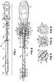
- the hand tool 10 is in the form of a ratcheting screwdriver, but it will be appreciated that the principles of the present invention would be applicable to other types of ratcheting drivers and other types of hand tools.
- the hand tool 10 includes an elongated handle 11, which is preferably formed of a suitable electrically insulating material, such as a suitable plastic material.
- the handle 10 may have an axial bore formed in the rear end thereof to define a storage compartment (not shown) closed by a removable cap 13.
- the handle 11 has an axial bore 14 formed in the forward end thereof, in which is received a metal insert 15, which may be of the type disclosed in U.S. patent no. 4,777,852.
- the insert 15 has an axial bore 16 formed in the forward end thereof for receiving therein a ratchet mechanism, generally designated by the numeral 20, which may be of the type disclosed in the aforementioned U.S. patent no. 4,777,852.
- the ratchet mechanism preferably includes an annular gear 21 rotatably mounted in the bore 16 coaxially therewith.
- the gear 21 defining an axial receptacle 22 which is circularly cylindrical in transverse cross section over most of its length, but is provided with a square end portion 23 at the rear end thereof.
- the insert 15 projects forwardly of the front end of the handle 11 and receives thereover a generally cup-shaped control cap 25, which has an inner core 26 and an outer cover 27 formed of a suitable electrically insulating material defining a generally cylindrical skirt portion 28.
- the cap 25 has a circular end wall which has centrally formed therethrough an axial bore 29.
- the control cap 29 is rotatable relative to the handle 11 and the insert 15 for shifting the ratchet mechanism 20 between forward and reverse conditions, all as is described in greater detail in the aforementioned U.S. patent no. 4,777,852, the disclosure of which is incorporated herein by reference.
- the hand tool 10 also includes a shaft assembly, generally designated by the numeral 30, which includes a metal coupler 31, a composite shank 40 and a coupling pin 50 joining the coupler 31 to the shank 40.
- the coupler 31 has a cylindrical main body portion 32 provided at the rear end thereof with an engagement end 33, which is substantially square in transverse cross section.
- the coupler 31 is dimensioned to be received in the receptacle 22 of the gear 21 with the engagement end 33 being mateably received in the square end portion 23 of the receptacle 22, as is shown in FIGS. 2 and 5.
- the cylindrical body 32 of the coupler 31 has a circular end face 35 in which is formed an axial bore 36, which is preferably circularly cylindrical in transverse cross section having a diameter D1 (see FIG. 4).
- the composite shank 40 may of the type disclosed in the aforementioned U.S. patent no. 5,259,277, the disclosure of which is also incorporated herein by reference. More specifically, the shank 40 may have a solid, electrically insulating core formed of pultruded polyester/glass material and an outer layer of glass/epoxy structure applied over the core along its entire length.
- the shank 40 is substantially circularly cylindrical in transverse cross section, having a circular end face 41 at a handle end thereof provided with a beveled edge, as at 41a.
- Formed in the end face 41 is an axial bore or recess 42, which is circular in transverse cross section and has a predetermined diameter D2 (see FIG.
- the shank 40 has a working end 43 which is preferably provided with a reduced-diameter tip 44 to facilitate coupling to an associated bit holder 45, which may formed of a suitable metal. More specifically, the bit holder 45 preferably has an axial recess 46 formed in the rear end thereof adapted to receive the reduced tip 44 of the shank 40 therein for fixed attachment thereto, as by the use of a suitable adhesive. The forward end of the bit holder 45 has formed axially therein a socket 47, which may be hexagonal in transverse cross section for removably receiving therein an associated bit 55. An elongated plastic sleeve 48 fits over the bit holder 45 and the adjacent end of the shank 40.
- the coupling pin 50 is formed of a suitable material, such as a hard steel, and is preferably hexagonal in transverse cross section having flats 51 intersecting at corners 52, the pin 50 having an across-corners dimension C (see FIGS. 3 and 4), which is preferably slightly greater than either of the diameters D1 or D2.
- one end of the coupling pin 50 is press-fitted in the axial bore 36 of the coupler 31, while the other end of the coupling pin 50 is press fitted in the axial bore 42 of the shank 40.
- the length of the pin 50 and the depths of the bores 36 and 42 are such that the parts can be joined together with the end faces 35 and 41 of the coupler 31 and shank 40 being disposed in abutting contact with each other, as shown in FIG. 2.
- the coupler 31 has a length such that, when it is fully seated in the receptacle 22 of the ratchet mechanism 20, the end face 35 thereof does not project axially outwardly beyond the end of the control cap 25.
- bit holder 45 does not project axially outwardly beyond the forward end of the sleeve 48.
- the bit 55 is the bit 55, which is adapted to be received in the bit holder 45 of the handle 10 for rotational driving thereby, all in a known manner.
- the shaft assembly 30 provides a good electrically insulating shank construction while, at the same time, having a metal coupler 31 which has the wear resistance characteristics sufficient to stand up to repeated insertion and removal in the ratchet mechanism 20 and rotational engagement therewith.
- the use of the press-fitted coupling pin 50 permits a firm, rigid, non-rotational coupling between the coupler 31 and the shank 40, despite the dissimilarity of the materials thereof.
- the coupling pin 50 is preferably press-fitted in bores in the coupler 31 and the shank 40, the shanks 40 could be insert molded around one end of the pin 50.
Landscapes
- Engineering & Computer Science (AREA)
- Mechanical Engineering (AREA)
- Details Of Spanners, Wrenches, And Screw Drivers And Accessories (AREA)
- Manufacturing Of Electrical Connectors (AREA)
- Insulating Bodies (AREA)
Abstract
Description
Claims (20)
- An insulating hand tool comprising:an elongated shank formed of an electrically insulating material and having a handle end and a working end and a longitudinal axis and an axial recess in the handle end,a handle formed of electrically insulating material and having an axial receptacle in one end thereof,a metal coupler receivable in said receptacle and having a axial bore in one end thereof, anda hexagonal connecting pin having first and second ends respectively disposed in said recess and said bore for joining said shank to said coupler.
- The hand tool of claim 1, wherein said shank has a composite construction.
- The hand tool of claim 2, wherein said shank includes a core formed of a glass-fiber-reinforced plastic material.
- The hand tool of claim 1, and further comprising a bit holder coupled to said shank at the working end thereof and adapted for receiving an associated bit.
- The hand tool of claim 1, wherein each of said recess and said bore is substantially circularly cylindrical in transverse cross section.
- The hand tool of claim 5, wherein said recess and said bore respectively have first and second predetermined diameters, said hexagonal connecting pin having an across-corners dimension slightly greater than either of said predetermined diameters.
- The hand tool of claim 1, wherein said handle end of said shank has a first end face and said one end of said coupler has a second end face, said connecting pin joining said shank to said coupler in a connected condition wherein said first and second faces are disposed in abutting contact with each other.
- The hand tool of claim 1, wherein said receptacle includes a first engagement portion of non-circular transverse cross section, said coupler including a second engagement portion of non-circular transverse cross section mateably engageable in said first engagement portion of said receptacle.
- The hand tool of claim 1, wherein said connecting pin is formed of suitable steel.
- The hand tool of claim 1, wherein said connecting pin is press-fitted in said recess and said bore.
- An insulating ratcheting driver tool comprising:an elongated shank formed of an electrically insulating material and having a handle end and a working end and a longitudinal axis and a first axial recess in the handle end,a handle formed of electrically insulating material and having a second axial recess in one end thereof,ratchet mechanism disposed in said second recess and including a gear and a pawl assembly engageable with said gear,said ratchet mechanism defining a receptacle,a metal coupler receivable in said receptacle for engagement with said ratchet mechanism and having an axial bore in one end thereof, anda hexagonal connecting pin having first and second ends respectively disposed in said first recess and said bore for joining said shank to said coupler.
- The driver tool of claim 11, wherein said shank has a composite construction.
- The driver tool of claim 12, wherein said shank includes a core formed of a glass-fiber-reinforced plastic material.
- The driver tool of claim 11, and further comprising a bit holder coupled to said shank at the working end thereof and adapted for receiving an associated bit.
- The driver tool of claim 11, wherein each of said first recess and said bore is substantially circularly cylindrical in transverse cross section.
- The driver tool of claim 15, wherein said first recess and said bore respectively have first and second predetermined diameters, said hexagonal connecting pin having an across-corners dimension slightly greater than either of said predetermined diameters.
- The driver tool of claim 11, wherein said handle end of said shank has a first end face and said one end of said coupler has a second end face, said connecting pin joining said shank to said coupler in a connected condition wherein said first and second faces are disposed in abutting contact with each other.
- The driver tool of claim 11, wherein said receptacle includes a first engagement portion of non-circular transverse cross section, said coupler including a second engagement portion of non-circular transverse cross section mateably engageable in said first engagement portion of said receptacle.
- The driver tool of claim 11, wherein said connecting pin is formed of suitable steel.
- The driver tool of claim 11, wherein said connecting pin is press-fitted in said first recess and said bore.
Applications Claiming Priority (2)
| Application Number | Priority Date | Filing Date | Title |
|---|---|---|---|
| US39077799A | 1999-09-07 | 1999-09-07 | |
| US390777 | 1999-09-07 |
Publications (3)
| Publication Number | Publication Date |
|---|---|
| EP1116555A2 true EP1116555A2 (en) | 2001-07-18 |
| EP1116555A3 EP1116555A3 (en) | 2002-07-03 |
| EP1116555B1 EP1116555B1 (en) | 2006-08-02 |
Family
ID=23543891
Family Applications (1)
| Application Number | Title | Priority Date | Filing Date |
|---|---|---|---|
| EP00119606A Expired - Lifetime EP1116555B1 (en) | 1999-09-07 | 2000-09-07 | Ratcheting composite screwdriver |
Country Status (4)
| Country | Link |
|---|---|
| US (1) | US6260445B1 (en) |
| EP (1) | EP1116555B1 (en) |
| JP (1) | JP2001162545A (en) |
| DE (1) | DE60029738D1 (en) |
Cited By (1)
| Publication number | Priority date | Publication date | Assignee | Title |
|---|---|---|---|---|
| EP2673518B1 (en) * | 2011-02-08 | 2018-02-28 | Stanley Works (Europe) GmbH | Improved electrically insulating electrical rotation coupling device and tool adaptor comprising such a device |
Families Citing this family (14)
| Publication number | Priority date | Publication date | Assignee | Title |
|---|---|---|---|---|
| USD525101S1 (en) | 2002-03-04 | 2006-07-18 | Maxtech Manufacturing, Inc. | Screw guide |
| CA98829S (en) | 2002-03-04 | 2004-08-31 | Maxtech Mfg Inc | Screw guide |
| US7302792B2 (en) * | 2003-10-16 | 2007-12-04 | The Johns Hopkins University | Pulsed plasma thruster and method of making |
| US7287451B2 (en) * | 2005-03-08 | 2007-10-30 | Kinpack Polyethylene Ltd. | Multiple bit screwdriver |
| US20080178712A1 (en) * | 2007-01-30 | 2008-07-31 | Brown Daniel P | Hand Tool With Torque Drive Shaft |
| USD572104S1 (en) | 2007-01-30 | 2008-07-01 | Loggerhead Tools Llc | Driver tool |
| USD576465S1 (en) | 2007-05-07 | 2008-09-09 | Loggerhead Tools Llc | Foldable driver tool |
| AU2008280818A1 (en) * | 2007-07-23 | 2009-01-29 | Zeljko Mandic | Insulating hand tool |
| CN102756349B (en) * | 2012-08-02 | 2015-03-11 | 浙江拓进五金工具有限公司 | Multifunctional ratchet wrench |
| DE102016200507A1 (en) * | 2015-01-30 | 2016-08-18 | Ngk Spark Plug Co., Ltd. | Gas sensor and method for producing a gas sensor |
| WO2017059519A1 (en) | 2015-10-04 | 2017-04-13 | Gerard Grand | Multi-implement tool |
| GB201905295D0 (en) * | 2019-04-15 | 2019-05-29 | Buchanan Nigel | Dual direction ratcheting device |
| US11597073B2 (en) * | 2021-03-29 | 2023-03-07 | Yih Cheng Factory Co., Ltd. | Hand tool with insulation handle |
| WO2024023526A2 (en) * | 2022-07-27 | 2024-02-01 | Nigel Buchanan | Insulated ratcheting screwdriver |
Family Cites Families (24)
| Publication number | Priority date | Publication date | Assignee | Title |
|---|---|---|---|---|
| US3519294A (en) | 1967-01-27 | 1970-07-07 | Conolon Corp | Internal ferrule joint |
| FR2135386B1 (en) * | 1971-05-03 | 1973-05-11 | Busseau Suzanne | |
| US4235133A (en) | 1979-07-11 | 1980-11-25 | Ignacio Acevedo | Torque-applying freely-reversible tool and drive-handle coupling |
| US4715739A (en) | 1981-02-18 | 1987-12-29 | Ciba-Geigy Corporation | Connection between a plastics quill shaft and a metal element |
| US4777852A (en) | 1986-10-02 | 1988-10-18 | Snap-On Tools Corporation | Ratcheting screwdriver |
| US5046387A (en) | 1987-10-02 | 1991-09-10 | Levake Rodney D | Stabilized, multifunctional tool handle |
| US4832573A (en) | 1987-11-27 | 1989-05-23 | General Motors Corporation | Integral connection for plastic water pump impeller |
| US5031272A (en) | 1990-02-28 | 1991-07-16 | Carmien Joseph A | Tool handle and method of attaching a handle to a percussive tool head |
| DE9016232U1 (en) | 1990-11-29 | 1991-03-21 | Fa. Andreas Stihl, 71336 Waiblingen | Form-locking coupling for a hand tool |
| US5063797A (en) | 1991-01-17 | 1991-11-12 | Huang Daniel C L | Hand-held tool for rotatably driving a bit |
| US5213014A (en) | 1991-06-10 | 1993-05-25 | Joseph Allen Carmien | Closed back shovel and method of assembly |
| US5375486A (en) | 1991-06-10 | 1994-12-27 | Carmien; Joseph A. | Surface protective striking tools |
| CA2061648C (en) | 1992-02-21 | 1994-12-13 | Albert Koehler | Screwdriver |
| US5259277A (en) * | 1992-07-13 | 1993-11-09 | Snap-On Tools Corporation | Electrically insulating composite hand tool |
| US5359911A (en) * | 1993-06-30 | 1994-11-01 | U.S. Composites Corp. | Lightweight self-insulating composite tool |
| US5526724A (en) | 1993-08-10 | 1996-06-18 | Bruggeman; Homer F. | Screw driver with palm knob |
| US5437212A (en) * | 1993-12-02 | 1995-08-01 | Snap-On Incorporated | Ratcheting screwdriver |
| US5515754A (en) | 1994-06-08 | 1996-05-14 | Cooper Industries, Inc. | Rotary hand tool |
| US5490437A (en) | 1994-08-25 | 1996-02-13 | Hebert; Paul W. | Hammer |
| US5533429A (en) | 1994-11-30 | 1996-07-09 | Kozak; Burton | Fastener driving tool insert |
| US5711193A (en) * | 1995-02-27 | 1998-01-27 | Snap-On Technologies, Inc. | Reversible ratcheting screwdriver with improved reversing ring |
| US5535648A (en) | 1995-02-27 | 1996-07-16 | Snap-On Technologies, Inc. | Ratcheting screwdriver |
| US5894765A (en) | 1995-05-26 | 1999-04-20 | Anderson; Wayne | Rear ratchet drive multiple bit tool |
| US5957014A (en) | 1998-01-13 | 1999-09-28 | Tseng; Hung Kui | Tool combination having two sections |
-
2000
- 2000-09-05 JP JP2000311278A patent/JP2001162545A/en active Pending
- 2000-09-07 EP EP00119606A patent/EP1116555B1/en not_active Expired - Lifetime
- 2000-09-07 DE DE60029738T patent/DE60029738D1/en not_active Expired - Lifetime
-
2001
- 2001-01-22 US US09/767,047 patent/US6260445B1/en not_active Expired - Lifetime
Cited By (1)
| Publication number | Priority date | Publication date | Assignee | Title |
|---|---|---|---|---|
| EP2673518B1 (en) * | 2011-02-08 | 2018-02-28 | Stanley Works (Europe) GmbH | Improved electrically insulating electrical rotation coupling device and tool adaptor comprising such a device |
Also Published As
| Publication number | Publication date |
|---|---|
| US6260445B1 (en) | 2001-07-17 |
| JP2001162545A (en) | 2001-06-19 |
| DE60029738D1 (en) | 2006-09-14 |
| EP1116555A3 (en) | 2002-07-03 |
| EP1116555B1 (en) | 2006-08-02 |
Similar Documents
| Publication | Publication Date | Title |
|---|---|---|
| EP1116555B1 (en) | Ratcheting composite screwdriver | |
| US7036401B2 (en) | Extendable spline-drive socket system | |
| US6378402B1 (en) | Hand tool | |
| US5409333A (en) | Multiply functioned drill means | |
| US6626071B2 (en) | Multi-functional hand tool assembly with storage handle and multiple tool attachments | |
| US4947713A (en) | Elastomeric sleeve on rearward portion of wrench socket to facilitate recognition and selection of the socket | |
| US4404874A (en) | Screwdriver with replaceable blade | |
| US5749271A (en) | Dual purpose ratchet screwdriver | |
| US6354177B2 (en) | 6-in-1 rotary tool | |
| EP0928665A2 (en) | Bit-storing handle | |
| US11565383B2 (en) | Electrically isolated adapter | |
| US3343577A (en) | Swivel top ratchet driver | |
| EP1078718B1 (en) | Drilling and fastener driving tool | |
| CA2702372A1 (en) | Multi-purpose tool | |
| CA2118072A1 (en) | Ratcheting screwdriver | |
| US6973860B2 (en) | Split-tip screwdriver with protective sleeve | |
| US7444908B2 (en) | Tool handle drivable by other tool | |
| US5899127A (en) | Variable-length screwdriver | |
| US4776246A (en) | Combination screwdriver hand tool | |
| US20040231468A1 (en) | Hand or automatic driven tool for attaching screwed anchors | |
| US6405396B1 (en) | Screwdriver assembly with an extendable rod | |
| US5592862A (en) | Compact, high torque, multi-drive screwdriver | |
| CA1220058A (en) | Drive attachment for a power drill or like tool | |
| EP0747178A1 (en) | Composite screwdriver with bit holder | |
| US6076440A (en) | Tool assembly |
Legal Events
| Date | Code | Title | Description |
|---|---|---|---|
| PUAI | Public reference made under article 153(3) epc to a published international application that has entered the european phase |
Free format text: ORIGINAL CODE: 0009012 |
|
| AK | Designated contracting states |
Kind code of ref document: A2 Designated state(s): AT BE CH CY DE DK ES FI FR GB GR IE IT LI LU MC NL PT SE |
|
| AX | Request for extension of the european patent |
Free format text: AL;LT;LV;MK;RO;SI |
|
| PUAL | Search report despatched |
Free format text: ORIGINAL CODE: 0009013 |
|
| AK | Designated contracting states |
Kind code of ref document: A3 Designated state(s): AT BE CH CY DE DK ES FI FR GB GR IE IT LI LU MC NL PT SE |
|
| AX | Request for extension of the european patent |
Free format text: AL;LT;LV;MK;RO;SI |
|
| RIC1 | Information provided on ipc code assigned before grant |
Free format text: 7B 25B 15/04 A, 7B 25B 15/02 B, 7B 25G 1/12 B |
|
| 17P | Request for examination filed |
Effective date: 20021206 |
|
| AKX | Designation fees paid |
Designated state(s): DE ES FR GB IT |
|
| 17Q | First examination report despatched |
Effective date: 20040503 |
|
| GRAP | Despatch of communication of intention to grant a patent |
Free format text: ORIGINAL CODE: EPIDOSNIGR1 |
|
| GRAS | Grant fee paid |
Free format text: ORIGINAL CODE: EPIDOSNIGR3 |
|
| GRAA | (expected) grant |
Free format text: ORIGINAL CODE: 0009210 |
|
| AK | Designated contracting states |
Kind code of ref document: B1 Designated state(s): DE ES FR GB IT |
|
| PG25 | Lapsed in a contracting state [announced via postgrant information from national office to epo] |
Ref country code: IT Free format text: LAPSE BECAUSE OF FAILURE TO SUBMIT A TRANSLATION OF THE DESCRIPTION OR TO PAY THE FEE WITHIN THE PRESCRIBED TIME-LIMIT;WARNING: LAPSES OF ITALIAN PATENTS WITH EFFECTIVE DATE BEFORE 2007 MAY HAVE OCCURRED AT ANY TIME BEFORE 2007. THE CORRECT EFFECTIVE DATE MAY BE DIFFERENT FROM THE ONE RECORDED. Effective date: 20060802 |
|
| REG | Reference to a national code |
Ref country code: GB Ref legal event code: FG4D |
|
| REF | Corresponds to: |
Ref document number: 60029738 Country of ref document: DE Date of ref document: 20060914 Kind code of ref document: P |
|
| PGFP | Annual fee paid to national office [announced via postgrant information from national office to epo] |
Ref country code: FR Payment date: 20060918 Year of fee payment: 7 |
|
| PGFP | Annual fee paid to national office [announced via postgrant information from national office to epo] |
Ref country code: ES Payment date: 20060926 Year of fee payment: 7 |
|
| PGFP | Annual fee paid to national office [announced via postgrant information from national office to epo] |
Ref country code: DE Payment date: 20061031 Year of fee payment: 7 |
|
| PG25 | Lapsed in a contracting state [announced via postgrant information from national office to epo] |
Ref country code: DE Free format text: LAPSE BECAUSE OF FAILURE TO SUBMIT A TRANSLATION OF THE DESCRIPTION OR TO PAY THE FEE WITHIN THE PRESCRIBED TIME-LIMIT Effective date: 20061103 |
|
| PG25 | Lapsed in a contracting state [announced via postgrant information from national office to epo] |
Ref country code: ES Free format text: LAPSE BECAUSE OF FAILURE TO SUBMIT A TRANSLATION OF THE DESCRIPTION OR TO PAY THE FEE WITHIN THE PRESCRIBED TIME-LIMIT Effective date: 20061113 |
|
| EN | Fr: translation not filed | ||
| PLBE | No opposition filed within time limit |
Free format text: ORIGINAL CODE: 0009261 |
|
| STAA | Information on the status of an ep patent application or granted ep patent |
Free format text: STATUS: NO OPPOSITION FILED WITHIN TIME LIMIT |
|
| 26N | No opposition filed |
Effective date: 20070503 |
|
| PG25 | Lapsed in a contracting state [announced via postgrant information from national office to epo] |
Ref country code: FR Free format text: LAPSE BECAUSE OF FAILURE TO SUBMIT A TRANSLATION OF THE DESCRIPTION OR TO PAY THE FEE WITHIN THE PRESCRIBED TIME-LIMIT Effective date: 20070511 |
|
| PGFP | Annual fee paid to national office [announced via postgrant information from national office to epo] |
Ref country code: GB Payment date: 20190927 Year of fee payment: 20 |
|
| REG | Reference to a national code |
Ref country code: GB Ref legal event code: PE20 Expiry date: 20200906 |
|
| PG25 | Lapsed in a contracting state [announced via postgrant information from national office to epo] |
Ref country code: GB Free format text: LAPSE BECAUSE OF EXPIRATION OF PROTECTION Effective date: 20200906 |