EP1116467A2 - Shower door bar with recessed grip - Google Patents
Shower door bar with recessed grip Download PDFInfo
- Publication number
- EP1116467A2 EP1116467A2 EP01100734A EP01100734A EP1116467A2 EP 1116467 A2 EP1116467 A2 EP 1116467A2 EP 01100734 A EP01100734 A EP 01100734A EP 01100734 A EP01100734 A EP 01100734A EP 1116467 A2 EP1116467 A2 EP 1116467A2
- Authority
- EP
- European Patent Office
- Prior art keywords
- door
- fastener
- escutcheon
- bar
- attachment end
- Prior art date
- Legal status (The legal status is an assumption and is not a legal conclusion. Google has not performed a legal analysis and makes no representation as to the accuracy of the status listed.)
- Withdrawn
Links
Images


Classifications
-
- A—HUMAN NECESSITIES
- A47—FURNITURE; DOMESTIC ARTICLES OR APPLIANCES; COFFEE MILLS; SPICE MILLS; SUCTION CLEANERS IN GENERAL
- A47K—SANITARY EQUIPMENT; ACCESSORIES THEREFOR, e.g. TOILET ACCESSORIES
- A47K10/00—Body-drying implements; Toilet paper; Holders therefor
- A47K10/04—Towel racks; Towel rails; Towel rods; Towel rolls, e.g. rotatable
- A47K10/10—Towel racks; Towel rails; Towel rods; Towel rolls, e.g. rotatable characterised by being mounted on cabinets, walls, doors, or the like
-
- A—HUMAN NECESSITIES
- A47—FURNITURE; DOMESTIC ARTICLES OR APPLIANCES; COFFEE MILLS; SPICE MILLS; SUCTION CLEANERS IN GENERAL
- A47K—SANITARY EQUIPMENT; ACCESSORIES THEREFOR, e.g. TOILET ACCESSORIES
- A47K3/00—Baths; Showers; Appurtenances therefor
- A47K3/28—Showers or bathing douches
- A47K3/30—Screens or collapsible cabinets for showers or baths
- A47K3/34—Slidable screens
Definitions
- “Bypass” type sliding shower doors can cover the entry to a shower stall. They often have glass or plastic door panels contained within metal frames which slide along parallel tracks. The doors are typically sized to overlap in the center of the entry. Narrow spacing between the tracks and the overlap prevent water from splashing out between the doors.
- Such doors often have towel/grip bars mounted to the frame of each door, one door with a bar inside the shower stall and the other door with a bar outside the shower stall. See generally U.S. patent 5,860,538.
- these bars also act as handles for opening and closing the shower doors. Since the doors must be spaced close together to avoid leaking, ordinarily such bars cannot be located on both sides of each door because they would prevent the doors from moving past each other. Thus, a person at one side of the shower stall entryway can easily open only one of the doors, since the other door has no corresponding bar on that side to be used as a handle.
- the present invention provides a towel bar assembly for mounting on a door, such as a bypass type slidable shower door, having an opening therethrough.
- the assembly includes a bar having at least one attachment end, an escutcheon having a front with an axial opening in which the attachment end is disposed, and a back having a flange around a rear opening.
- the recessed grip is a cupped surface
- the bar also has a second attachment end
- the assembly also has a second such escutcheon and a second such fastener.
- the fastener preferably has threads which mate with threads on the attachment end.
- the invention provides a door assembly.
- a door having front and rear sides, and an aperture extending therebetween.
- a bar having at least one attachment end extending towards the door, an escutcheon having a front with an axial opening in which the attachment end is disposed, and a back having a flange around a rear opening.
- the flange is of a size such that the escutcheon cannot pass completely through the door aperture.
- fastener having a back end with a flange around a rearwardly directed recessed grip, the fastener is positioned through the door aperture, the fastener flange being sized such that it prevents the fastener from passing completely through the door aperture.
- the fastener is inserted in the rear opening of the escutcheon and mated with one of the escutcheon and the attachment end so that the flanges clamp the door between them around the aperture.
- the grip can be used to reposition the door from the rear side of the door.
- a towel bar 10 of the present invention is used with standard bypass-style shower doors 12, 14 covering an entry to a conventional shower stall 15.
- Each door 12, 14 is preferably a single panel of glass free from framing at its sides.
- One towel bar 10 can be suitably mounted to each of the doors 12, 14.
- the towel bar 10 includes a bar 16, two escutcheons 18, and two nut/fasteners 20.
- the bar 16 preferably comprises a tubular rod having a region 20 for hanging towels and having two attachment ends 22, 24 extending substantially perpendicular.
- the ends 22, 24 include an engagement member 26, preferably consisting of external threads.
- Each escutcheon 18 is preferably bell-shaped having a front 28 and a rear 30. At the front 28 an axial bore 32 extends into each escutcheon 18 to define a cylindrical hub 40 supported at its circumference by walls 42 extending to an interior surface of each escutcheon 18.
- Each door 12, 14 has a set of two suitably located door apertures 64.
- Each axial bore 32 includes a front engagement member 44, preferably consisting of internal threads matable with the threads 26.
- a circumferential flange 48 extends around the periphery of the rear 30 of each escutcheon 18. Each flange 48 is sized larger than a corresponding aperture 64 and defines a catch surface 50, as will be described.
- Each fastener 20 includes a front end 52 and a back end 54, with the front end 52 sized to fit within a corresponding escutcheon 18 through the rear side opening 46.
- the front end 52 of each fastener defines a cylindrical hub 56 having an axial opening, such as bore 58, concentric with the axial bores 32 of the escutcheons.
- the hub 56 is supported by a plurality of radially extending walls 60 tapering from the front end 52 to an annular surface 62 having a circumference sized to fit within a corresponding door aperture 64 and escutcheon rear side opening 46.
- each fastener 20 defines a circumferential flange 66 of a greater diameter than the annular surface 62 and having a catch surface 68 similar to that of the escutcheons 18. Also at the back end 54 of each fastener 20 is a recessed grip 70, preferably in the form of a cupped surface 72 extending inwardly toward a door within the diameter of the annular surface 62. At the periphery of the cupped surface 72, a lateral ridge 74 extends outwardly to a back surface 76 of each fastener 20. The back surface 76 joins the catch surface 68 at a chamferred edge 78.
- the axial bore 58 of each fastener 20 includes an internal engagement member 80 preferably consisting of threads matable with the threads 26 of a corresponding towel support attachment end 22, 24.
- the towel bar 10 is attached to a shower door 14 by inserting the end 52 of each fastener 20 into the corresponding apertures 64 in the door 14.
- the apertures 64 are sized to receive the annular surface 62 of the fastener 20, but have a diameter less than that of the flange 66. In this way, each flange catch surface 68 will prevent the fastener 20 from passing completely through the door apertures 64.
- the front end 52 of the fasteners 20 will project past the thickness of the doors 12, 14 and will be disposed within the escutcheons 18.
- the front end 52 of the fasteners 20 and the cylindrical hub 40 of the escutcheons 18 are sized so that when assembled, each escutcheon flange catch surface 48 will contact an opposite surface of one of the doors 12, 14.
- the attachment ends 22, 24 of the towel support 16 can be threaded into the bore 32 in the escutcheons 18.
- Each towel bar is secured to the shower doors 12, 14 by rotating the escutcheons 18 and the fasteners 20 until the catch surfaces 50, 68 press firmly against each side of the doors 12, 14.
- An optional gasket (not shown) or sealant may be positioned at the catch surfaces 50, 68 of the escutcheons 18 and fasteners 20 to further ensure that water does not leak through the door apertures 64.
- a towel bar 10 of the present invention is attached to each door 12, 14 of a bypass shower door with the bar 16 extending outwardly on the outer door 14 and inwardly on the inner door 12.
- the towel bars 10 thus do not interfere with the sliding motion of the doors 12, 14 because of the narrow profile of the fasteners 20.
- each door 12, 14 may be opened from both sides using either the bar 16 or the recessed grips 70.
- the doors 12, 14 can be opened at the fastener side by inserting a finger or thumb into one or both of the recessed grips 70 and applying a slightly inward and sideways pressure on the cupped surface 72.
- the towel bar 10 of the present invention provides "handles" at both sides of the doors 12, 14, while maintaining a sufficiently narrow gap 90 between the doors so that water will not normally leak outside the shower stall at the gap 90.
- the present invention permits the towel bar 10 to be mounted directly to a glass or plastic panel, so that no frame is needed for mounting the handle. This reduces material costs and provides for more pleasant looking shower doors.
- the towel bar is not constrained by the size and location of a door frame, such that it can be any suitable length and configuration.
- Figs. 5A-5F show alternate end connections of the towel bar 10 to the doors 12, 14. For each embodiment, both end connections are identical, therefore, only one is shown and described. Similar parts are shown with similar numerals, albeit with a suitable designation such as "A,” “B,” “C” where the part is different.
- a towel bar 10A has a fastener 20A identical to that described above. However front threads 100, at annular surface 62A, mate with rear threads at the interior of an escutcheon 18A.
- the escutcheon 18A does not have threads at an axial bore 32A such that end engagement member 26A of a bar 16A attachment end 22A mates only with the internal engagement member 58 of the fastener 20A and not with the escutcheon 18A.
- this embodiment does not include a cylindrical hub around the axial bore 32A or interior hub support walls.
- a towel bar 10B has an escutcheon 18B with front 44 and rear 102 threads.
- the front threads at the axial bore 32 mate with end engagement member 26B of a towel support 16B attachment end 22B and the rear threads at the interior of the escutcheon 18B mate with the external engagement member 100 at a annular surface 62B of a fastener 20B, as in embodiment 10A.
- the front end 52B of the fastener 20B does not include an axial bore or internal threads and is not directly mated with the towel support.
- a towel bar 10C has an escutcheon 18C with no engagement members and a fastener 20C with only the internal engagement member 80, preferably threads, at the axial bore 58 for mating with end engagement member 26C of a towel support 16C attachment end 22C.
- a stop member 104 is suitably located along the towel support 16C which retains the escutcheons 18C to the door 14 by contacting an outer surface 106 at the front side 28 of the escutcheon 18C.
- the stop member 104 is preferably a fixed annular ring, but it can be any suitable configuration provided it is sized larger than an axial bore 32C of the escutcheon 18C. Since axial bore is not threaded, the cylindrical hub and interior walls of the escutcheon of the preferred embodiment are not needed.
- a towel bar 10D has a fastener 20D with the external engagement member 100 at its annular surface 62D matable with the rear engagement member 102 at the interior of an escutcheon 18D.
- a front end 52D of a fastener 20D has no axial bore or internal engagement member.
- an axial bore 32D of the escutcheon 18D does not include an engagement member.
- a preferably retractable or removable stop member 108 such as a nut, is fastened to end 22D at end engagement member 26D of a towel support 16D.
- the stop member 108 is sized larger than the axial bore 32D and contacts an interior ledge 107 of the escutcheon 18D.
- the escutcheon 18D is secured to the fastener 20D and a towel support 16D is held in place by contact of the fastener 20D to an end surface 110 of the towel support 16D and the stop member 108 to the ledge 107. Since the escutcheon 18D does not include a threaded axial bore, no cylindrical hub and interior walls are needed.
- a front end 52E of a fastener 20E has a smaller diameter than that of the embodiments described above defining a threaded rod or bolt-like end.
- an escutcheon 18E has separate axial bores 32F and 111 with respective front 44 and rear 102E engagement members, preferably threads.
- Hub 113 defines the axial bore 111 and is supported by interior walls 42E, which also support the hub 40E of axial bore 32E.
- the front 44 and rear 102E engagement members mate with external engagement member 100E of the fastener 20E and an end engagement member 26E of attachment end 22E of the towel support 16E, respectively.
- the bottom of each axial bore 32E, 111 can provide a positive stop for the fastener 20E and towel support 16E.
- a front end 52F of a fastener 20F may be a threaded rod (as in towel bar 10E) that mates at external engagement member 100F with engagement member 44F within a lengthwise axial bore 32F of an escutcheon 18F.
- the bore 32F is defined and supported by hub 40F and radial walls 42F.
- the other end of the axial bore 32F mates with the engagement member 26F of the towel support 16F attachment end 22F.
- the escutcheon 18F may have a suitably configured opening 46F and annular surface 112 for fitting around the annular surface 62F of the recessed grip 70 and within the door aperture 64.
- the above disclosure provides a towel bar for use with bypass-style shower doors.
Landscapes
- Health & Medical Sciences (AREA)
- Public Health (AREA)
- Residential Or Office Buildings (AREA)
- Bathtubs, Showers, And Their Attachments (AREA)
- Extensible Doors And Revolving Doors (AREA)
Abstract
Description
- "Bypass" type sliding shower doors can cover the entry to a shower stall. They often have glass or plastic door panels contained within metal frames which slide along parallel tracks. The doors are typically sized to overlap in the center of the entry. Narrow spacing between the tracks and the overlap prevent water from splashing out between the doors.
- Such doors often have towel/grip bars mounted to the frame of each door, one door with a bar inside the shower stall and the other door with a bar outside the shower stall. See generally U.S. patent 5,860,538.
- Besides providing a place to suspend wet towels for drying, these bars also act as handles for opening and closing the shower doors. Since the doors must be spaced close together to avoid leaking, ordinarily such bars cannot be located on both sides of each door because they would prevent the doors from moving past each other. Thus, a person at one side of the shower stall entryway can easily open only one of the doors, since the other door has no corresponding bar on that side to be used as a handle.
- Accordingly, an improved bar assembly for bypass shower doors is needed.
- The present invention provides a towel bar assembly for mounting on a door, such as a bypass type slidable shower door, having an opening therethrough. The assembly includes a bar having at least one attachment end, an escutcheon having a front with an axial opening in which the attachment end is disposed, and a back having a flange around a rear opening. There is also a fastener having a back end with a flange around a rearwardly directed recessed grip. The fastener is inserted in the rear opening of the escutcheon and mated with one of the escutcheon and the attachment end so that the flanges define a gap therebetween. The recessed grip is then accessible from the rear of the assembly.
- In preferred forms the recessed grip is a cupped surface, the bar also has a second attachment end, and the assembly also has a second such escutcheon and a second such fastener. The fastener preferably has threads which mate with threads on the attachment end.
- In another aspect the invention provides a door assembly. There is a door having front and rear sides, and an aperture extending therebetween. There is also a bar having at least one attachment end extending towards the door, an escutcheon having a front with an axial opening in which the attachment end is disposed, and a back having a flange around a rear opening. The flange is of a size such that the escutcheon cannot pass completely through the door aperture.
- There is also a fastener having a back end with a flange around a rearwardly directed recessed grip, the fastener is positioned through the door aperture, the fastener flange being sized such that it prevents the fastener from passing completely through the door aperture. The fastener is inserted in the rear opening of the escutcheon and mated with one of the escutcheon and the attachment end so that the flanges clamp the door between them around the aperture. When the parts are so assembled, the grip can be used to reposition the door from the rear side of the door.
- These assemblies permit there to be handles than can easily be gripped on both sides of each door, even in a bypass system. Thus, a door can easily be opened even from the opposite side from which the towel bar projects. The assembly achieves this by providing a low-profile grip on one side of the door that extends inwardly through the door panel itself (rather than outwardly).
- The foregoing and other advantages of the invention will appear from the following description. In this description reference is made to the accompanying drawings which form a part hereof and in which there is shown by way of illustration preferred embodiments of the invention. These embodiments do not represent the full scope of the invention. Thus, the claims should be looked to in order to judge the scope of the invention.
-
- Fig. 1 is a front view of a shower enclosure on which is mounted assemblies of the present invention;
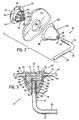
- Fig. 2 is a cut-away exploded view of one end connection of a towel bar of Fig. 1;
- Fig. 3 is a cross-sectional view taken along line 3-3 of Fig. 1;
- Fig. 4 is an enlarged view, partially in section, taken along line 4-4 of Fig. 1; and
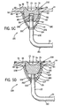
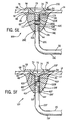
- Figs. 5A-5F show cross-sections of alternate end connections of the towel bar of the present invention.
-
- A
towel bar 10 of the present invention is used with standard bypass-style shower doors conventional shower stall 15. Eachdoor towel bar 10 can be suitably mounted to each of thedoors - The
towel bar 10 includes abar 16, twoescutcheons 18, and two nut/fasteners 20. Thebar 16 preferably comprises a tubular rod having aregion 20 for hanging towels and having two attachment ends 22, 24 extending substantially perpendicular. Theends engagement member 26, preferably consisting of external threads. - Each
escutcheon 18 is preferably bell-shaped having afront 28 and a rear 30. At thefront 28 anaxial bore 32 extends into eachescutcheon 18 to define acylindrical hub 40 supported at its circumference bywalls 42 extending to an interior surface of eachescutcheon 18. Eachdoor door apertures 64. Eachaxial bore 32 includes afront engagement member 44, preferably consisting of internal threads matable with thethreads 26. At the rear there is alarge opening 46 of increased diameter than, and concentric with, theaxial bore 32. Acircumferential flange 48 extends around the periphery of the rear 30 of eachescutcheon 18. Eachflange 48 is sized larger than acorresponding aperture 64 and defines acatch surface 50, as will be described. - Each
fastener 20 includes afront end 52 and aback end 54, with thefront end 52 sized to fit within acorresponding escutcheon 18 through the rear side opening 46. Thefront end 52 of each fastener defines acylindrical hub 56 having an axial opening, such asbore 58, concentric with theaxial bores 32 of the escutcheons. Thehub 56 is supported by a plurality of radially extendingwalls 60 tapering from thefront end 52 to anannular surface 62 having a circumference sized to fit within acorresponding door aperture 64 and escutcheonrear side opening 46. - The
end 54 of eachfastener 20 defines acircumferential flange 66 of a greater diameter than theannular surface 62 and having acatch surface 68 similar to that of theescutcheons 18. Also at theback end 54 of eachfastener 20 is arecessed grip 70, preferably in the form of acupped surface 72 extending inwardly toward a door within the diameter of theannular surface 62. At the periphery of thecupped surface 72, alateral ridge 74 extends outwardly to aback surface 76 of eachfastener 20. Theback surface 76 joins thecatch surface 68 at a chamferrededge 78. Theaxial bore 58 of eachfastener 20 includes aninternal engagement member 80 preferably consisting of threads matable with thethreads 26 of a corresponding towelsupport attachment end - The
towel bar 10 is attached to ashower door 14 by inserting theend 52 of eachfastener 20 into thecorresponding apertures 64 in thedoor 14. Theapertures 64 are sized to receive theannular surface 62 of thefastener 20, but have a diameter less than that of theflange 66. In this way, eachflange catch surface 68 will prevent thefastener 20 from passing completely through thedoor apertures 64. - The
front end 52 of thefasteners 20 will project past the thickness of thedoors escutcheons 18. Thefront end 52 of thefasteners 20 and thecylindrical hub 40 of theescutcheons 18 are sized so that when assembled, each escutcheonflange catch surface 48 will contact an opposite surface of one of thedoors towel support 16 can be threaded into thebore 32 in theescutcheons 18. Each towel bar is secured to theshower doors escutcheons 18 and thefasteners 20 until the catch surfaces 50, 68 press firmly against each side of thedoors escutcheons 18 andfasteners 20 to further ensure that water does not leak through thedoor apertures 64. - Referring to Fig. 4, a
towel bar 10 of the present invention is attached to eachdoor bar 16 extending outwardly on theouter door 14 and inwardly on theinner door 12. The towel bars 10 thus do not interfere with the sliding motion of thedoors fasteners 20. - Importantly, each
door bar 16 or the recessed grips 70. Thedoors cupped surface 72. Thus, thetowel bar 10 of the present invention provides "handles" at both sides of thedoors narrow gap 90 between the doors so that water will not normally leak outside the shower stall at thegap 90. Also, the present invention permits thetowel bar 10 to be mounted directly to a glass or plastic panel, so that no frame is needed for mounting the handle. This reduces material costs and provides for more pleasant looking shower doors. Moreover, the towel bar is not constrained by the size and location of a door frame, such that it can be any suitable length and configuration. - Figs. 5A-5F show alternate end connections of the
towel bar 10 to thedoors - Referring in particular to Fig. 5A, a
towel bar 10A has afastener 20A identical to that described above. Howeverfront threads 100, atannular surface 62A, mate with rear threads at the interior of anescutcheon 18A. In this embodiment, theescutcheon 18A does not have threads at anaxial bore 32A such thatend engagement member 26A of abar 16A attachment end 22A mates only with theinternal engagement member 58 of thefastener 20A and not with theescutcheon 18A. As such, this embodiment does not include a cylindrical hub around theaxial bore 32A or interior hub support walls. - Referring next to Fig. 5B, a
towel bar 10B has anescutcheon 18B withfront 44 and rear 102 threads. The front threads at theaxial bore 32 mate withend engagement member 26B of atowel support 16B attachment end 22B and the rear threads at the interior of theescutcheon 18B mate with theexternal engagement member 100 at aannular surface 62B of afastener 20B, as inembodiment 10A. In this embodiment, thefront end 52B of thefastener 20B does not include an axial bore or internal threads and is not directly mated with the towel support. - Referring to Fig. 5C, a towel bar 10C has an
escutcheon 18C with no engagement members and afastener 20C with only theinternal engagement member 80, preferably threads, at theaxial bore 58 for mating withend engagement member 26C of atowel support 16C attachment end 22C. Astop member 104 is suitably located along thetowel support 16C which retains theescutcheons 18C to thedoor 14 by contacting anouter surface 106 at thefront side 28 of theescutcheon 18C. Thestop member 104 is preferably a fixed annular ring, but it can be any suitable configuration provided it is sized larger than anaxial bore 32C of theescutcheon 18C. Since axial bore is not threaded, the cylindrical hub and interior walls of the escutcheon of the preferred embodiment are not needed. - Referring to Fig. 5D, a
towel bar 10D has afastener 20D with theexternal engagement member 100 at itsannular surface 62D matable with therear engagement member 102 at the interior of anescutcheon 18D. In this embodiment, afront end 52D of afastener 20D has no axial bore or internal engagement member. Moreover, anaxial bore 32D of theescutcheon 18D does not include an engagement member. Rather, a preferably retractable or removable stop member 108, such as a nut, is fastened to end 22D atend engagement member 26D of atowel support 16D. The stop member 108 is sized larger than theaxial bore 32D and contacts aninterior ledge 107 of theescutcheon 18D. As such, theescutcheon 18D is secured to thefastener 20D and atowel support 16D is held in place by contact of thefastener 20D to anend surface 110 of thetowel support 16D and the stop member 108 to theledge 107. Since theescutcheon 18D does not include a threaded axial bore, no cylindrical hub and interior walls are needed. - Referring to Fig. 5E, in
towel bar 10E, afront end 52E of afastener 20E has a smaller diameter than that of the embodiments described above defining a threaded rod or bolt-like end. In this embodiment, anescutcheon 18E has separateaxial bores respective front 44 and rear 102E engagement members, preferably threads. Hub 113 defines theaxial bore 111 and is supported byinterior walls 42E, which also support thehub 40E ofaxial bore 32E. The front 44 and rear 102E engagement members mate withexternal engagement member 100E of thefastener 20E and anend engagement member 26E ofattachment end 22E of thetowel support 16E, respectively. The bottom of eachaxial bore fastener 20E andtowel support 16E. - Referring to Fig. 5F, in still another
alternate embodiment 10F, afront end 52F of afastener 20F may be a threaded rod (as intowel bar 10E) that mates atexternal engagement member 100F withengagement member 44F within a lengthwiseaxial bore 32F of anescutcheon 18F. Thebore 32F is defined and supported byhub 40F andradial walls 42F. The other end of theaxial bore 32F mates with theengagement member 26F of thetowel support 16F attachment end 22F. Also, in this embodiment, theescutcheon 18F may have a suitably configuredopening 46F andannular surface 112 for fitting around theannular surface 62F of the recessedgrip 70 and within thedoor aperture 64. - The above disclosure provides a towel bar for use with bypass-style shower doors.
Claims (8)
- A towel bar assembly for mounting on a door having an opening therethrough, comprising:wherein the fastener is inserted in the rear opening and mated with one of the escutcheon and the attachment end so that the flanges define a gap therebetween, and so that the recessed grip is accessible from the rear of the assembly.a bar having at least one attachment end;an escutcheon having a front with an axial opening in which the attachment end is disposed, and a back having a flange around a rear opening; anda fastener having a back end with a flange around a rearwardly directed recessed grip;
- The towel bar assembly of claim 1, wherein the recessed grip is a cupped surface.
- The towel bar assembly of claim 1, wherein the bar also has a second attachment end, and the assembly further comprises a second such escutcheon and a second such fastener.
- The towel bar assembly of claim 1, wherein the fastener has threads which mate with threads on the attachment end.
- A door assembly, comprising:a door having front and rear sides, and an aperture extending therebetween;a bar having at least one attachment end extending towards the door;an escutcheon having a front with an axial opening in which the attachment end is disposed, and a back having a flange around a rear opening, wherein the flange is of a size such that the escutcheon cannot pass completely through the door aperture; anda fastener having a back end with a flange around a rearwardly directed recessed grip, the fastener being positioned through the door aperture, the fastener flange being sized such that it prevents the fastener from passing completely through the door aperture;wherein the fastener is inserted in the rear opening of the escutcheon and mated with one of the escutcheon and the attachment end so that the flanges clamp the door between them around the aperture; andwherein the grip can be used to reposition the door from the rear side of the door.
- The door assembly of claim 5, wherein the recessed grip is a rearwardly accessible cupped surface.
- The door assembly of claim 5, wherein the bar also has a second attachment end, and the assembly further comprises a second such escutcheon and a second such fastener connecting the second attachment end to the door at a second aperture through the door.
- The door assembly of claim 5, wherein the fastener further comprises threads which mate with threads on the attachment end.
Applications Claiming Priority (2)
| Application Number | Priority Date | Filing Date | Title |
|---|---|---|---|
| US482364 | 2000-01-13 | ||
| US09/482,364 US6250044B1 (en) | 2000-01-13 | 2000-01-13 | Shower door bar with recessed grip |
Publications (2)
| Publication Number | Publication Date |
|---|---|
| EP1116467A2 true EP1116467A2 (en) | 2001-07-18 |
| EP1116467A3 EP1116467A3 (en) | 2003-05-21 |
Family
ID=23915756
Family Applications (1)
| Application Number | Title | Priority Date | Filing Date |
|---|---|---|---|
| EP01100734A Withdrawn EP1116467A3 (en) | 2000-01-13 | 2001-01-12 | Shower door bar with recessed grip |
Country Status (7)
| Country | Link |
|---|---|
| US (1) | US6250044B1 (en) |
| EP (1) | EP1116467A3 (en) |
| CN (1) | CN100401963C (en) |
| AU (1) | AU781011B2 (en) |
| CA (1) | CA2330871C (en) |
| MX (1) | MXPA01000435A (en) |
| NZ (1) | NZ509347A (en) |
Families Citing this family (30)
| Publication number | Priority date | Publication date | Assignee | Title |
|---|---|---|---|---|
| US6371423B1 (en) * | 2001-01-26 | 2002-04-16 | The Group Legacy, L.C. | Tubular rod and post assembly |
| US6578235B2 (en) * | 2001-05-11 | 2003-06-17 | Overhead Door Corporation | Universal inside-outside door handle |
| US7090225B2 (en) * | 2003-06-03 | 2006-08-15 | Aqua Glass Corporation | Water-proof seal for a towel bar which penetrates a tub surround portion |
| US6966101B2 (en) * | 2003-09-23 | 2005-11-22 | Door & Window Hardware Co. | Handle of a glass door |
| US7309593B2 (en) * | 2003-10-01 | 2007-12-18 | Surmodics, Inc. | Attachment of molecules to surfaces |
| US6938868B2 (en) * | 2003-10-29 | 2005-09-06 | Charles Pence | Method and apparatus for supporting a thin, rigid panel |
| US20060043039A1 (en) * | 2004-08-27 | 2006-03-02 | Custom Hardware Mfg. Inc. | Integrated posts/ferrule |
| US20060156466A1 (en) * | 2005-01-19 | 2006-07-20 | Gatco, Inc. | Grab bar assembly |
| US20090188879A1 (en) * | 2008-01-28 | 2009-07-30 | Ming-Dang Shieh | Towel Rack |
| US20100199569A1 (en) * | 2009-02-06 | 2010-08-12 | Daniel Piedade | Oversized, stress-transferring spacer for window assembly, and window assembly incorporating the same |
| US20110024372A1 (en) * | 2009-07-31 | 2011-02-03 | Wu Ming-Ken | Bath Curtain Rack |
| CA2734667C (en) * | 2011-03-24 | 2012-01-03 | Groupe Vfg Inc. | Glass handle connector for glass door handle |
| US20130325670A1 (en) | 2012-05-30 | 2013-12-05 | Liberty Hardware Mfg. Corp. | Shower door assembly display and retail |
| US20140223697A1 (en) * | 2013-02-11 | 2014-08-14 | Cre8Tive Hardware, Inc. | Removable Hardware Structure |
| US9309691B2 (en) * | 2013-10-07 | 2016-04-12 | Door & Window Hardware Co. | Sliding-door handle device |
| US9676543B2 (en) | 2014-01-29 | 2017-06-13 | Liberty Hardware Mfg. Corp. | Shower door glass pane packaging assembly |
| USD767380S1 (en) | 2014-01-29 | 2016-09-27 | Liberty Hardware Mfg. Corp. | Packaging castors |
| USD758771S1 (en) | 2014-01-29 | 2016-06-14 | Liberty Hardware Mfg. Corp. | Shower door display |
| USD763023S1 (en) | 2014-01-29 | 2016-08-09 | Liberty Hardware Mfg. Corp. | Shower door display |
| US10070739B2 (en) | 2014-01-29 | 2018-09-11 | Liberty Hardware Mfg. Corp. | Shower door assembly display |
| US20150216373A1 (en) * | 2014-01-31 | 2015-08-06 | J. Logan Pyeatt | Towel Access Shower Door |
| TWM485004U (en) * | 2014-05-15 | 2014-09-01 | Jin Ju Han Ind Corp | Improved structure of placement frame for bathroom articles |
| USD777564S1 (en) | 2015-03-13 | 2017-01-31 | Liberty Hardware Mfg. Corp. | Carton divider |
| US9907415B2 (en) * | 2015-03-13 | 2018-03-06 | Liberty Hardware Mfg. Corp. | Article divider assembly |
| US9743810B2 (en) | 2015-07-31 | 2017-08-29 | Liberty Hardware Mfg. Corp. | Shower door guide assembly |
| US12345060B2 (en) | 2018-11-09 | 2025-07-01 | Anchor Ring Solutions, Llc | Construction anchor apparatus and system and methodology of use |
| US10689841B2 (en) * | 2018-11-09 | 2020-06-23 | Anchor Ring Solutions, Llc | Construction anchoring system, apparatus and methodology |
| US11781296B2 (en) | 2020-11-20 | 2023-10-10 | Kohler Co. | Shower trim assembly |
| US11719019B2 (en) * | 2020-12-01 | 2023-08-08 | Kohler Co. | Handle assembly for a shower door |
| US20220356660A1 (en) * | 2021-05-04 | 2022-11-10 | P. T. Atlas Manufacturing LLC | Barrier connection |
Citations (1)
| Publication number | Priority date | Publication date | Assignee | Title |
|---|---|---|---|---|
| US5860538A (en) | 1997-01-16 | 1999-01-19 | Kohler Co. | Accessory attachment system |
Family Cites Families (7)
| Publication number | Priority date | Publication date | Assignee | Title |
|---|---|---|---|---|
| US2134096A (en) * | 1937-07-12 | 1938-10-25 | W B Jarvis Company | Handle securing structure |
| US2589516A (en) | 1948-09-01 | 1952-03-18 | Otto E Stelzer | Bar mounting |
| US3359573A (en) * | 1964-11-12 | 1967-12-26 | Ralph T Casebolt | Glass shower enclosure door |
| US3378219A (en) | 1967-01-13 | 1968-04-16 | Illinois Tool Works | Plastic fastener |
| US4499629A (en) | 1983-05-06 | 1985-02-19 | Forms & Surfaces | Door pull mounting and locking assembly |
| US4998321A (en) * | 1990-01-17 | 1991-03-12 | Kohler Co. | Handle assembly |
| US5875903A (en) * | 1998-01-08 | 1999-03-02 | Chen; Wen-San | Bathroom hanger rack |
-
2000
- 2000-01-13 US US09/482,364 patent/US6250044B1/en not_active Expired - Lifetime
-
2001
- 2001-01-12 NZ NZ509347A patent/NZ509347A/en not_active IP Right Cessation
- 2001-01-12 MX MXPA01000435A patent/MXPA01000435A/en active IP Right Grant
- 2001-01-12 CA CA002330871A patent/CA2330871C/en not_active Expired - Fee Related
- 2001-01-12 EP EP01100734A patent/EP1116467A3/en not_active Withdrawn
- 2001-01-15 AU AU15005/01A patent/AU781011B2/en not_active Ceased
- 2001-01-15 CN CNB011008318A patent/CN100401963C/en not_active Expired - Fee Related
Patent Citations (1)
| Publication number | Priority date | Publication date | Assignee | Title |
|---|---|---|---|---|
| US5860538A (en) | 1997-01-16 | 1999-01-19 | Kohler Co. | Accessory attachment system |
Also Published As
| Publication number | Publication date |
|---|---|
| AU1500501A (en) | 2001-07-19 |
| CN1309944A (en) | 2001-08-29 |
| CA2330871C (en) | 2008-05-27 |
| US6250044B1 (en) | 2001-06-26 |
| CA2330871A1 (en) | 2001-07-13 |
| MXPA01000435A (en) | 2003-06-19 |
| NZ509347A (en) | 2003-01-31 |
| CN100401963C (en) | 2008-07-16 |
| AU781011B2 (en) | 2005-04-28 |
| EP1116467A3 (en) | 2003-05-21 |
Similar Documents
| Publication | Publication Date | Title |
|---|---|---|
| CA2330871C (en) | Shower door bar with recessed grip | |
| CA2004267C (en) | Hanger with improved positioning structure | |
| US5860538A (en) | Accessory attachment system | |
| US6302457B1 (en) | Easy-to-install door lock with improved anti-torque effect for outside rose assembly | |
| US20060272231A1 (en) | Housing assembly | |
| NZ576645A (en) | A door furniture mounting assembly with a rosette adapter so that substantially the same hardware maybe used to attached a handle to a door regardless of the hole size already made | |
| ATE293734T1 (en) | ACTUATING FITTING FOR A SLIDING SINGLE | |
| US4829632A (en) | Handle assembly or the like | |
| US7007986B2 (en) | Access cover fastening device | |
| US20030056556A1 (en) | Lever door lock device | |
| US6038714A (en) | Concealed grab bar | |
| EP2331781B1 (en) | Catch for handle bolt, particularly for roof windows | |
| US20040256886A1 (en) | Shell structure for electrocar | |
| US20060156466A1 (en) | Grab bar assembly | |
| KR200355677Y1 (en) | Window frame having ventilating-hole | |
| KR200325942Y1 (en) | fixing device for door | |
| US6353179B1 (en) | Cable entry system | |
| US6696642B1 (en) | Wiring installation device | |
| JPH0323023Y2 (en) | ||
| US20170167187A1 (en) | Cover for cleanout access | |
| CN213269294U (en) | Handle (CN) | |
| KR200298116Y1 (en) | auxiliary hinge | |
| KR200283690Y1 (en) | Hinge for a door | |
| KR200327730Y1 (en) | door secession check device | |
| KR200338119Y1 (en) | Hinge for a door |
Legal Events
| Date | Code | Title | Description |
|---|---|---|---|
| PUAI | Public reference made under article 153(3) epc to a published international application that has entered the european phase |
Free format text: ORIGINAL CODE: 0009012 |
|
| AK | Designated contracting states |
Kind code of ref document: A2 Designated state(s): AT BE CH CY DE DK ES FI FR GB GR IE IT LI LU MC NL PT SE TR |
|
| AX | Request for extension of the european patent |
Free format text: AL;LT;LV;MK;RO;SI |
|
| RIN1 | Information on inventor provided before grant (corrected) |
Inventor name: KOPACZ, THOMAS H. Inventor name: DEBRAAL, TIMOTHY S. Inventor name: FUNK, DAVID R. |
|
| PUAL | Search report despatched |
Free format text: ORIGINAL CODE: 0009013 |
|
| AK | Designated contracting states |
Designated state(s): AT BE CH CY DE DK ES FI FR GB GR IE IT LI LU MC NL PT SE TR |
|
| AX | Request for extension of the european patent |
Extension state: AL LT LV MK RO SI |
|
| RIC1 | Information provided on ipc code assigned before grant |
Ipc: 7A 47K 10/10 B Ipc: 7A 47K 3/34 A |
|
| 17P | Request for examination filed |
Effective date: 20031021 |
|
| AKX | Designation fees paid |
Designated state(s): DE FR IT |
|
| STAA | Information on the status of an ep patent application or granted ep patent |
Free format text: STATUS: THE APPLICATION IS DEEMED TO BE WITHDRAWN |
|
| 18D | Application deemed to be withdrawn |
Effective date: 20120801 |