EP1115251A2 - Packet transmitting system with channel selection at receiver - Google Patents
Packet transmitting system with channel selection at receiver Download PDFInfo
- Publication number
- EP1115251A2 EP1115251A2 EP00120489A EP00120489A EP1115251A2 EP 1115251 A2 EP1115251 A2 EP 1115251A2 EP 00120489 A EP00120489 A EP 00120489A EP 00120489 A EP00120489 A EP 00120489A EP 1115251 A2 EP1115251 A2 EP 1115251A2
- Authority
- EP
- European Patent Office
- Prior art keywords
- data
- packet
- signal transmission
- packets
- section
- Prior art date
- Legal status (The legal status is an assumption and is not a legal conclusion. Google has not performed a legal analysis and makes no representation as to the accuracy of the status listed.)
- Granted
Links
- 230000005540 biological transmission Effects 0.000 claims abstract description 137
- 238000001824 photoionisation detection Methods 0.000 abstract 4
- 238000010586 diagram Methods 0.000 description 17
- 238000000034 method Methods 0.000 description 13
- 238000009792 diffusion process Methods 0.000 description 4
- 239000000284 extract Substances 0.000 description 2
- 125000004122 cyclic group Chemical group 0.000 description 1
- 230000001934 delay Effects 0.000 description 1
- 230000003111 delayed effect Effects 0.000 description 1
- 238000004519 manufacturing process Methods 0.000 description 1
Images






Classifications
-
- H—ELECTRICITY
- H04—ELECTRIC COMMUNICATION TECHNIQUE
- H04L—TRANSMISSION OF DIGITAL INFORMATION, e.g. TELEGRAPHIC COMMUNICATION
- H04L5/00—Arrangements affording multiple use of the transmission path
-
- H—ELECTRICITY
- H04—ELECTRIC COMMUNICATION TECHNIQUE
- H04N—PICTORIAL COMMUNICATION, e.g. TELEVISION
- H04N21/00—Selective content distribution, e.g. interactive television or video on demand [VOD]
- H04N21/20—Servers specifically adapted for the distribution of content, e.g. VOD servers; Operations thereof
- H04N21/23—Processing of content or additional data; Elementary server operations; Server middleware
- H04N21/236—Assembling of a multiplex stream, e.g. transport stream, by combining a video stream with other content or additional data, e.g. inserting a URL [Uniform Resource Locator] into a video stream, multiplexing software data into a video stream; Remultiplexing of multiplex streams; Insertion of stuffing bits into the multiplex stream, e.g. to obtain a constant bit-rate; Assembling of a packetised elementary stream
- H04N21/2362—Generation or processing of Service Information [SI]
-
- H—ELECTRICITY
- H04—ELECTRIC COMMUNICATION TECHNIQUE
- H04N—PICTORIAL COMMUNICATION, e.g. TELEVISION
- H04N21/00—Selective content distribution, e.g. interactive television or video on demand [VOD]
- H04N21/20—Servers specifically adapted for the distribution of content, e.g. VOD servers; Operations thereof
- H04N21/23—Processing of content or additional data; Elementary server operations; Server middleware
- H04N21/235—Processing of additional data, e.g. scrambling of additional data or processing content descriptors
-
- H—ELECTRICITY
- H04—ELECTRIC COMMUNICATION TECHNIQUE
- H04N—PICTORIAL COMMUNICATION, e.g. TELEVISION
- H04N21/00—Selective content distribution, e.g. interactive television or video on demand [VOD]
- H04N21/40—Client devices specifically adapted for the reception of or interaction with content, e.g. set-top-box [STB]; Operations thereof
- H04N21/43—Processing of content or additional data, e.g. demultiplexing additional data from a digital video stream; Elementary client operations, e.g. monitoring of home network or synchronising decoder's clock; Client middleware
- H04N21/435—Processing of additional data, e.g. decrypting of additional data, reconstructing software from modules extracted from the transport stream
-
- Y—GENERAL TAGGING OF NEW TECHNOLOGICAL DEVELOPMENTS; GENERAL TAGGING OF CROSS-SECTIONAL TECHNOLOGIES SPANNING OVER SEVERAL SECTIONS OF THE IPC; TECHNICAL SUBJECTS COVERED BY FORMER USPC CROSS-REFERENCE ART COLLECTIONS [XRACs] AND DIGESTS
- Y02—TECHNOLOGIES OR APPLICATIONS FOR MITIGATION OR ADAPTATION AGAINST CLIMATE CHANGE
- Y02D—CLIMATE CHANGE MITIGATION TECHNOLOGIES IN INFORMATION AND COMMUNICATION TECHNOLOGIES [ICT], I.E. INFORMATION AND COMMUNICATION TECHNOLOGIES AIMING AT THE REDUCTION OF THEIR OWN ENERGY USE
- Y02D30/00—Reducing energy consumption in communication networks
- Y02D30/70—Reducing energy consumption in communication networks in wireless communication networks
Definitions
- the present invention relates to a packet-transmitting system for performing code-division multiplexing on a stream of data packets and parallel transmission of data packets.
- a packet-transmitting system which comprises a transmitting station and a receiving station.
- error-correction codes are added to a stream to data packets, and the data packets are modulated and transmitted from the antenna.
- the antenna receives signals of all bands. The signals are demodulated and subjected to error correction, thereby reproducing the data packets.
- the packets are supplied to a packet-selecting circuit, which selects the packets having the ID the user has designated.
- the present invention has been made in view of the foregoing.
- the object of the invention is to provide a packet-transmitting system in which the receiver receives only the packet the user needs and the parameters of error-correction codes or the characteristics of signals can be changed for each packet (program) to achieve broadcasting in various manners desired.
- a packet-transmitting system has at least one control-signal transmission channel and a plurality of data-signal transmission channels.
- the system comprises a transmitter apparatus and a receiver apparatus.
- the transmitter apparatus includes: packet-allocating section for receiving a stream of packets and allocating groups of packets to the data-signal transmission channels; time-dividing/multiplexing section for receiving packet-group data representing the packets allocated to each data-signal transmission channel by the section and for time-dividing and multiplexing the packet-group data to the control-signal transmission channel; and multiplexer/adder section for multiplexing a signal in the control-signal transmission channel and signals in the data-signal transmission channels in parallel, thereby to generate signals to be transmitted.
- the receiver apparatus includes: signal-distributing section for distributing the signals to a plurality of channels; group-data acquiring section for reproducing the signal in the data-signal transmission channel from a signal distributed to any channel by the signal-distributing section, thereby to acquire group data about the data-signal transmission channels; channel-selecting section for selecting a data-signal transmission channel to which a packet group designated is allocated, in accordance with the group data acquired by the group-data acquiring section; and selected-channel reproducing section for reproducing a signal in the data-signal transmission channel selected by the channel-selecting section, from the signals in some of the transmission channels to which the signal-distributing section has distributed the signals and for extracting only the packets of the group designated, the signals in some transmission channels not having been used in the group-data acquiring section.
- the packet-allocating section may allocate the packets of the same group to a plurality of data-signal transmission channels, and the time-dividing/multiplexing section may time-divide and multiplex the packets thus allocated, as the packet-group data, to the control-signal transmission channel.
- the group data may represent packet identifiers that the packets have.
- the multiplexer/adder section may multiplex the signal in the control-signal transmission channel and the signals in the data-signal transmission channels, by section of a code dividing/multiplexing system.
- the transmitter apparatus may comprise time-management data correcting section for finding a difference between the timing of each packet to be allocated by the packet-allocating section and the timing of the same packet allocated by the packet-allocating section, and for correcting time-management data contained in the packet, in accordance with the difference.
- the transmitter apparatus may comprise scramble section for scrambling the packets in the data-signal transmission channels and time-dividing a scramble key to one of the data-signal transmission channels.
- the scramble section may eliminate a difference between a signal delay in the transmission channel for transmitting the scramble key and a signal delay in the transmission channels for transmitting the packets, before the scramble key and packets are transmitted.
- a transmitter apparatus for use in a packet-transmitting system having at least one control-signal transmission channel and a plurality of data-signal transmission channels.
- the transmitter apparatus comprises: packet-allocating section for receiving a stream of packets and allocating groups of packets to the data-signal transmission channels; time-dividing/multiplexing section for receiving packet-group data representing the packets allocated to each data-signal transmission channel by the packet-allocating section and for time-dividing and multiplexing the packet-group data to the control-signal transmission channel; and multiplexer/adder section for multiplexing a signal in the control-signal transmission channel and signals in the data-signal transmission channels in parallel, thereby to generate signals to be transmitted.
- a receiver apparatus for use in a packet-transmitting system having at least one control-signal transmission channel and a plurality of data-signal transmission channels.
- the receiver apparatus is designed to receive signals generated by allocating groups of packets to the data-signal transmission channels, by time-dividing and multiplexing, the control-signal transmission channel, packet-group data allocated to each of the data-signal transmission, channel and by multiplexing a signal in the control-signal transmission channel and signals in the data-signal transmission channels in parallel.
- the receiver apparatus comprises: signal-distributing section for distributing the signals to a plurality of channels; group-data acquiring section for reproducing the signal in the data-signal transmission channel from a signal distributed to any channel by the signal-distributing section, thereby to acquire group data about the data-signal transmission channels; channel-selecting section for selecting a data-signal transmission channel to which a packet group designated is allocated, in accordance with the group data acquired by the group-data acquiring section; and selected-channel reproducing section for reproducing a signal in the data-signal transmission channel selected by the channel-selecting section, from the signals in some of the transmission channels to which the signal-distributing section has distributed the signals and for extracting only the packets of the group designated, the signals in some transmission channels not having been used in the group-data acquiring section.
- FIG. 1 is a block diagram showing the transmitter incorporated in a packet-transmitting system according to the invention. It is assumed that the data input to the packet-transmitting system is TS (Transport Stream) type that is generally defined in MPEG2 systems.
- the TS data consists of packets of programs (groups) that are time-divided and multiplexed.
- the transmitter has a packet-allocating circuit 21 and a control-data generating circuit 23 0 .
- the packet-allocating circuit 21 is designed to receive packets and allocate them to transmission channels in accordance with the packet identifiers (PIDs) of those packet groups designated. More precisely, the circuit 21 allocates the packets identified by PIDs a 1 to b 1 to the transmission channel #1, the packets identified by PIDs a 2 to b 2 to the transmission channel #2, and so forth. Thus, the circuit 21 allocates the packets identified by PIDs aN to b N to the last transmission channel #N.
- PIDs packet identifiers
- the control-data generating circuit 23 0 is designed to generate parameters, control data and the like to synchronize the transmission channels #1 to #N. (Hereinafter, the parameters, the control data, and the like will be collectively called "control data.")
- the circuit 23 0 receives the packet-allocation data from the packet-allocating circuit 21.
- the packet-allocation data shows which packet has been allocated to which transmission channel.
- the circuit 23 0 performs time division and multiplexing on the packet-allocation data, generating packet-group data (groups of PIDs) and adding the same to the control data.
- control data The format of the control data will be described, with reference to FIGS. 2A and 2B and FIGS. 3 to 8.
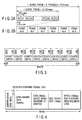
- the control data has been generated by time division and multiplexing of pilot symbols (PS) and frequency-diffused modulated signals (D), as is illustrated in FIG. 2A.
- PS pilot symbols
- D frequency-diffused modulated signals
- Each PS is a signal having a length of 125 ⁇ sec and modulated every 250 ⁇ sec with a sync diffusion code only.
- Each frequency-diffused modulated signal has been generated by diffusing data (e.g., a parameter) with the same sync diffusion code and has a length of 125 ⁇ sec.
- 51 pairs each consisting of one pilot symbol and one frequency-diffused modulated signal, constitute one frame. Every six frames constitute one super frame.
- each frame of the control data is composed of 51 pilot symbols and 51 frequency-diffused modulated signals D 1 to D 51 .
- the signals D 1 to D 51 are of the following types.
- the signal D 1 is a sync word having a fixed pattern and used to synchronize the frame of the control data.
- the signal D 1 is a frequency-diffused modulated signal that has been generated by diffusing, for example, "01101010101101010101100110001010" with the sync diffusion code.
- the signal D 2 is a sync word that indicates the ordinal number of the frame in the super frame. As shown in FIG. 3, the signal D 2 is a frequency-diffused modulated signal generated by diffusing, with the sync diffusion code, eight identical 4-bit binary numbers.
- the signal D 2 can have five values ranging, for example, from 0x0 to 0x5. These five values correspond to the six frames that constitute one super frame.
- the signals D 3 to D 50 have been generated by effecting byte interleaving and convolution coding on data, then diffusing the data, thus generating a frequency-diffused modulated signal, and finally dividing the signal every 125 ⁇ sec.
- the data diffused consists, as shown in FIG. 4, identification data (8 bits), a receiver-starting signal (1 bit), CDM-channel data (568 bits), data (48 bits) added when the receiver is started, CRC check bits (16 bits) for correcting errors, and bytes (128 bits) for checking a Reed-Solomon (RS) code.
- the identification data identifies the contents of the data that follows it. It is defined as is shown in, for example, Table 1. Value Contents of data 0000000 Not allocated 0000001 - 0011111 Reserved 0100000 Composed of CDM channel-configuration data and receiver-starting signal 0100001 - 1111110 Reserved 1111111 Not allocated
- the receiver-starting signal causes the receiver to start operating in case of emergency. For example, this one-bit signal is set at "1" to start the receiver. In any other case, the signal is set at "0.”
- the CDM-channel data is composed of a start CDM channel number (8 bits) and ten CDM channel-configuration data items (56 x 10 bits).
- the CDM channel-configuration data items correspond to ten channels, respectively.
- Each CDM channel-configuration data item (56 bits) is composed of interleave mode (4 bits), convolution mode (4 bits), TS-ID (16 bits), reserved state (3 bit), PID minimum value (13 bits), version number (3 bits), and PID maximum value (13 bits).
- the start CDM channel number indicates the CDM channel designated by the first CDM channel-configuration data item contained in the CDM-channel data.
- the nth CDM channel-configuration data item designates the start CDM channel number +n-1.
- the interleave mode is data that designates the interleave size of the CDM channel. This mode can have, for example, the values shown in the following Table 2. Value Interleave Size 0000 0 0001 53 0010 109 0011 218 0100 436 0101 654 0110 981 0111 1308 1000-1111 Reserved
- the convolution mode is data that defines the ratio of encoding the convolution code of the CDM channel. It can have, for example, the values shown in Table 3. Value Ratio of encoding convolution code 0000 Reserved 0001 Reserved 0010 Encoding ratio of 1/2 0011 Encoding ratio of 2/3 0100 Encoding ratio of 3/4 0101 Encoding ratio of 5/6 0110 Encoding ratio of 7/8 0111 - 1110 Reserved 1111 No allocation system
- TS-ID is data that represents the number of the transport stream to be transmitted through the CDM channel. This data is, for example, OxFFFF when there is no data to be transmitted through the CDM channel.
- the reserved state is a storage area that can be used as an extension area in the future.
- the PID minimum value is data representing the smallest value for the PID range of the TS packet to be transmitted through the CDM channel. If the same PID range is assigned to two or more CDM channels, the PID minimum value indicates that the CDM channels are bundled together to form a TS.
- the version number is data that is incremented by one every time parameters such as interleave length and encoding ratio are updated.
- the PID maximum value is data representing the greatest value for the PID range of the TS packet to be transmitted through the CDM channel. If the same PID range is assigned to two or more CDM channels, the PID minimum value indicates that the CDM channels are bundled together to form a TS.
- the data (48 bits) added when the receiver is started works effectively as auxiliary data for the receiver-starting signal.
- this data is composed of a type data item (4 bits), a region ID data item (12 bits), an emergency program TS-ID (16 bits), and an emergency program number (16 bits).
- the type data items represents an emergency level or the like.
- the region ID data item represent the regions to which an emergency program will be broadcast.
- the emergency program TS-ID identifies the emergency program to be broadcast.
- the emergency program number indicates the number assigned to the emergency program.
- the signals D 3 to D 50 can be transmitted not only in the form of the CDM channel-configuration data and the data added at the start of the receiver (see FIG. 4), but also in the form of extension data (616 bits) that may consists of data items of various types.
- D51 is a signal modulated with, for example, a diffused code for achieving synchronization and is stored in a reserved storage area.
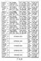
- the CDM channel-configuration data, the data added at the start of the receiver, the extension data and the like, all described above, are provided in the form of such a super frame as is illustrated in FIG. 8.
- the mark indicates a receiver-starting signal.
- the format of the control data has a region of CDM channel-configuration data and a region of extension data. These regions of the control-data format are utilized in the present invention.
- the packet-allocating circuit 21 allocates the input packets to the transmission channels, thus forming groups of packets.
- the packet groups are supplied to timing-correcting circuits 22 1 to 22 n , respectively.
- Each of the timing-correcting circuits 22 1 to 22 n corrects the time lag that occurs when the packet-allocating circuit 21 extracts packets from the stream of packets input to it. How the time lag is corrected will be explained with reference to FIGS. 9A and 9B.
- FIGS. 9A and 9B show how the kth timing-correcting circuit 22 k processes the packets input to it and having PIDs of a K to b K .
- the packets having PIDs of a K to b K may not have the same time positions as they have in the packet stream input to the packet-allocating circuit 21. Therefore, they may not be transmitted through the transmission channel #k, with those time position preserved. Hence, the timing-correcting circuit 22 k shifts the transmission timing of each packet. If the packets contain timing data (time management data) each, the timing-correcting circuit 22 k changes the timing data in each packet. If necessary, null packets are inserted in order to adjust the rate of transmitting packets.
- a typical example of the timing data is PCR (Program Clock Reference) data.
- the packets output from the timing-correcting circuits 22 1 to 22 n are supplied to scramble circuit 23 1 to 23 n , respectively.
- the packets are scrambled with a prescribed scramble key.
- the packets thus scrambled in the scramble circuit 23 1 to 23 n are supplied to error-correcting encoder circuit 24 1 to 24 n , respectively.
- the above-mentioned control data is supplied from the to an error-correcting encoder circuit 24 0 .
- the error-correcting encoder circuit 24 0 performs coding processes, such as Reed-Solomon coding, byte interleaving, convolution coding and bit interleaving, on the control data supplied from the control-data generating circuit 23 0 , thereby to correcting the control data. Similarly, each of the error-correcting encoder circuit 24 1 to 24 n performs these coding processes on the packet output from the corresponding scramble circuit, thereby correcting the packet.
- the control data corrected is supplied to a CDM modulation circuit 25 0 .
- the outputs of the error-correcting encoder circuit 24 1 to 24 n are supplied to CDM modulation circuits 25 1 to 25 n , respectively.
- Codes W 0 to W n are input to the modulation circuits 25 0 to 25 n , respectively.
- the CDM modulation circuit 25 0 performs CDM modulation on the control data.
- the CDM modulation circuits 25 1 to 25 n perform CDM modulation on the outputs of the error-correcting encoder circuit 24 1 to 24 n .
- the outputs of the CDM modulation circuit 25 0 to 25 n are supplied to a multiplexer/adder circuit 26.
- the multiplexer/adder circuit 26 multiplexes and adds outputs of the CDM modulation circuit 25 0 to 25 n , generating CDM signals.
- the CDM signals are transmitted from the transmitter through a prescribed transmission path, such as a ground-wave broadcast path, a satellite broadcast path or a cable broadcast path.
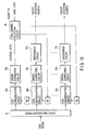
- FIG. 10 is a block diagram of the receiver incorporated in the packet-transmitting system.
- the antenna (not shown) receives the CDM signals transmitted from the transmitter.
- the CDM signals are supplied to a signal-distributing circuit 31.
- the circuit 31 distributes the CDM signals to n + 1 systems.
- the first system comprises a CDM demodulation circuit 32 0 , an error-correcting circuit 33 0 , and a CDM channel-selecting circuit 35.
- Each of the other systems comprises a CDM demodulation circuit, an error-correcting circuit, and a descramble circuit.
- the CDM signals distributed to the n+1 systems are supplied to the CDM demodulation circuits 32 0 to 32 n , respectively.
- the CDM demodulation circuits 32 0 to 32 n receive codes W 0 to W n . Using the codes W 0 to W n , the CDM demodulation circuits 32 0 to 32 n performs CDM demodulation on the CDM signals. The CDM signals, thus demodulated, are supplied to the error-correcting circuits 33 0 to 33 n .
- the error-correcting circuits 33 0 to 33 n perform coding processes, such as Reed-Solomon decoding, byte de-interleaving, convolution decoding and bit de-interleaving, on the control data supplied from the control-data generating circuit 23 0 , thereby to correcting the CDM signals demodulated in CDM demodulation circuits 32 0 to 32 n .
- the control data and the data packets for n channels are thereby generated.
- the control data is supplied to the CDM channel-selecting circuit 35.
- the CDM channel-selecting circuit 35 extracts group data from the control data.
- the group data represents various packet IDs.
- the circuit 35 selects the packet ID of the program the user has designated. Further, the circuit 35 identifies the channel for transmitting the program, in accordance with the group data containing the packet ID. Then, the circuit 35 generates only the code of the transmission channel thus identified.
- control data designates various packet identifiers (PIDs) that will be transmitted via all CDM channels, as is illustrated in FIG. 8.
- the CDM channel-selecting circuit 35 receives the data showing these packet identifiers, determines which transmission channel should be used to transmit the packet ID of the program the user has designated, and generates the code Wk of the transmission channel for transmitting the packet ID. Hence, only the CDM signals on this transmission channel are demodulated.
- the signals demodulated and selected in the processes described above are supplied to descramble circuits 34 1 to 24 n .
- the descramble circuits 34 1 to 24 n descramble the signals, which are output in the form of packets (i.e., programs desired).
- the receiver receives the control data, thereby recognizing the packets of each of the groups transmitted through one transmission channel. Hence, the receiver can receive the packets of only the group the user desired. This serves to reduce the size and power consumption of the receiver and, ultimately, the cost of the receiver.
- the packet-allocating circuit 21 may allocate these packets to two or more transmission channels.
- the transmitter and the receiver may be modified as is illustrated in FIG. 11A and FIG. 11B, respectively.
- FIG. 11A shows a modified transmitter. If the packets (having PIDs a k to a k ) of one group exceed the transmission capacity of the transmission channel #k in terms of data amount, the stream of packets output from a timing-correcting circuit 22 k and scrambled by a scramble circuit 23 k is supplied to a packet-allocating circuit 41 k .
- the packet-allocating circuit 41 k allocates the packets to error-correcting encoder circuits 24 k(1) to 24 k(M) , thus providing additional transmission channels.
- the circuits 24 k(1) to 24 k(M) correct encode the packets, which are input to CDM modulation circuits 25 k(1) to 25 k(M) .
- the circuits 25 k(1) to 25 k(M) perform CDM modulation on the packets.
- the packets thus modulated are supplied to a multiplexer/adder circuit 26.
- the multiplexer/adder circuit 26 multiplexes and adds the packets output from the CDM modulation circuits 25 k(1) to 25 k(M) , thereby generating CDM signals.
- Packet-group data which shows the group of packets transmitted via the same additional transmission channel, is added to the control data.
- FIG. 11B shows a modified receiver.
- a signal-distributing circuit 31 receives the CDM signals from the transmitter.
- the circuit 32 distributes the CDM signals in accordance with the additional channels provided in the transmitter.
- the CDM signals distributed to the channels #k(1) to #k(M) are supplied to CDM demodulation circuits 32 k(1) to 32 k(M) , respectively.
- the circuit performs CDM demodulation on the CDM signals.
- the CDM signals thus demodulated are supplied to error-correcting circuits 33 k(1) to 33 k(M) .
- the circuits 33 k(1) to 33 k(M) correct the CDM signals, which are supplied to a multiplexer/adder circuit 42 k .
- the multiplexer/adder circuit 42 k multiplexes and adds the CDM signals, thus generating a stream of packets.
- the packets are supplied to a descramble circuit 34 k , descrambled thereby and output from the receiver.
- the packets (having PIDs a k to a k ) of one group output from the packet-allocating circuit 21 exceed the transmission capacity of the transmission channel #k in the transmitter. Therefore, additional transmission channels #k(1) to #k(M) are provided in the transmitter.
- the timing-correcting circuit 22 k inserts null packets and corrects time data, as shown in FIGS. 9A and 9B, in order to transmit packets at a rate M times as high as the initial packet-transmitting rate.
- the packet-allocating circuit 41 k allocates the packets to the additional transmission channels #k(1) to #k(M), first to the channel #k(1), and last to the channel #k(M).
- the control data sets the PIDs of the packets to be transmitted via the channels #k(1) to #k(M) in the same range.
- the receiver it is known from the control data that a plurality additional channels provided for each transmission channel in the transmitter.
- the same error-correcting conditions such as interleave length, encoding ratio, are applied to the error-correcting encoder circuits 24 k(1) to 24 k(M) .
- codes W k(1) to W k(M) are set in order to receive the packets transmitted via the CDM channels.
- the receiver receives streams of packets.
- the packets of the first stream are multiplexed, whereby the packets of the first group, which have PIDs a k to b k are received.
- the packets of the second stream are multiplexed, and so forth.
- the packets of the last stream are multiplexed. Since the packets are sequentially multiplexed, stream by stream, the same error-correcting conditions (e.g., interleave length, encoding ratio and the like) can be applied to the error-correcting encoder circuits 24 k(1) to 24 k(M) . This makes it possible to restore the original packet stream in the receiver.
- the same error-correcting conditions e.g., interleave length, encoding ratio and the like
- the data packets of the same group are allocated to a plurality of channels. Therefore, the modified transmitter can transmit the packets of any group even if the packets of the group, i.e., the same program, exceed the transmission capacity of one channel.
- the input packets are not allocated to channels, in the first-stage component, i.e., the packet-allocating circuit 21. Rather, the packet-allocating circuit 41 k allocates the packets additional channels after the packets have been processed by the timing-correcting circuit 22 k and the scramble circuit 23 k .
- the packet-allocating circuit 41 k allocates the packets additional channels after the packets have been processed by the timing-correcting circuit 22 k and the scramble circuit 23 k .
- one descramble circuit and one timing-correcting circuit can process all groups of packets.
- a transmission delay may exists between a transmission channel for transmitting a scramble key and a transmission channel for transmitting packets, due to the difference in characteristic between the error-correction codes used in the respective transmission channels. Some process must be effected in the transmitter to eliminate such a transmission delay.
- a scramble circuit that is modified to eliminate the transmission delay will be described, with reference to FIG. 12.
- FIG. 12 is a block diagram.
- the modified scramble circuit shown in FIG. 12 has the function of eliminating the transmission delay, unlike the scramble circuit 23 k illustrated in FIG. 11A. Assume that the delay time of the error-correcting encoder circuit in the transmitter and decoder circuit in the receiver of the CDM channel #1 is T1, whereas the delay time of the error-correcting encoder circuit in the transmitter and decoder circuit in the receiver of the CDM channel #k is T M .
- the scramble circuit 23 k comprises a scramble process circuit 23 k1 , a key-generating circuit 23 k2 , two delay circuits 23 k3 and 23 k4 , and a control circuit 23 k5 .
- the key-generating circuit 23 k2 generates a scramble key.
- the scramble key is supplied via the delay circuit 23 k3 to the scramble process circuit 23 k1 and to the delay circuit 23 k4 .
- the scramble process circuit 23 k1 scrambles the stream of packets allocated to the CDM channel #k, by using the scramble key supplied from the key-generating circuit 23 k2 .
- the scramble key supplied to the delay circuit 23 k4 is subjected to time division and multiplexing in the CDM channel #k.
- the scramble circuit 23 k receives the data items representing the time delay T 1 of the CDM channel #1 and the time delay T M of the CDM channel #k.
- the data items are input to the control circuit 23 k5 .
- the control circuit 23 k5 sets the delay times of the delay circuits 23 k3 and 23 k4 at D M and D 1 , respectively.
- FIG. 13 is a timing chart showing the timing of transmitting data packets in the case where the delay time T 1 is longer than the delay time T M , that is, T 1 > T M .
- the timing of transmitting the scramble key is delayed by (T 1 - T M ) unless time correction is performed.
- the scrambling can be effected at a correct timing, by inserting a delay time D M that is equal to the difference (T 1 - T M ) in the delay circuit 23 k3 .
- the scrambling can be carried out at a correcting timing, by inserting the delay time D 1 that is equal to the difference (T M - T 1 ) in the delay circuit 23 k4 .
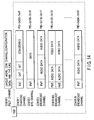
- FIG. 14 is a diagram showing a stream of MPEG2-T packets, which are allocated to a plurality of CDM transmission channels.
- the channel CDM#0 is a pilot channel (i.e., control channel) for transmitting the TSIDs (i.e., groups of PIDs).
- the channels CDM#1 and CDM#2 transmits charge data (including the scramble-key data), program-arrangement data, program-related data and the like.
- the channels CDM#4 and CDM#5 are combined together to transmit packets having the same packet ID.
- FIG. 15 is a flowchart representing the sequence of selecting a program in the receiver of the packet-transmitting system according to the present invention.
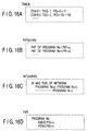
- the receiver receives a pilot signal through the pilot channel #0 (Step S1). Then, the receiver acquires a table of CDM channels, TSIDs and PIDs, which is shown in FIG. 16A (Step S2). Further, the receiver receives TSIDs through the charging CDM channel #1 (Step S3). The receiver acquires an NIT, which is shown in FIG. 16B (Step S4).
- Step S5 it is determined whether any user program number has been input to the receiver (S5). If NO in Step S5, it is determined whether or not a user program number exists in another TSID of the same 25 MHz band (Step S6). If YES in Step S6, the TSID received is changed (Step S7), and Steps S3 to S6 are repeated. If NO in Step S6, it is determined whether or not a user program number exists in a TSID of another 25 MHz band (Step S8). If YES in Step S8, the transponder is changed to another (Step S9). In this case, Steps S1 to S8 are repeated. If NO in Step S8, the receiver waits for a user program number.
- Step S5 the receiver acquires an PAT, which is shown in FIG. 16B (Step S10).
- Step S14 ends the sequence of selecting a program in the receiver.
- the packet-transmitting system can be used to accomplish, for example, digital broadcasting. If so, in the receiver of the system, the input data packets, i.e., programs (groups), are time-divided and multiplexed. The packets are thereby allocated to a plurality of transmission channels. One or more of the transmission channels are assigned as channels for transmitting control data. Using the control data, the packet-group data, which shows the groups of packets to be transmitted via the transmission channel, respectively, is transmitted from the transmitter to the receiver. In the receiver, the packets of each group are recognized from the control data. The receiver can therefore easily select and receive only the data packet the user desires. This reduces the size and power consumption of the receiver and, ultimately, the cost of the receiver.
- groups programs
- a program i.e., one group of packets, can be transmitted even if the packets exceed the transmission capacity of one channel in terms of data amount. This is because the packets of the same group are allocated to a plurality of transmission channels. In the receiver, it can be known from the control data that these transmission channels are bundled together.
- the timing of each packet in the packet stream may not be maintained and may need to be shifted. Even in this case, the packets can be reproduced in the receiver, merely by correcting the time management data contained in each packet.
- the transmission channel for transmitting a scramble key has a delay time and the transmission channel for transmitting packets scrambled may have different delay times because the error-correction codes used in the these channels differ in terms of their characteristic. In this case, the difference in delay time between these channels can be eliminated in the transmitter before the scramble key and the packets are transmitted via the two channels, respectively.
- packets are multiplexed and transmitted by the CDM transmission system. Nonetheless, other various multiplex transmission systems, including the OFDM system, can be applied to the present invention.
- the present invention can provide a packet-transmitting system in which the receiver apparatus receives only the packet the user needs and the parameters of error-correction codes or the characteristics of signals cannot be changed for each packet to achieve broadcasting in various manners desired.
Landscapes
- Engineering & Computer Science (AREA)
- Signal Processing (AREA)
- Multimedia (AREA)
- Computer Networks & Wireless Communication (AREA)
- Time-Division Multiplex Systems (AREA)
- Data Exchanges In Wide-Area Networks (AREA)
- Television Systems (AREA)
Abstract
Description
time-dividing/multiplexing section for receiving packet-group data representing the packets allocated to each data-signal transmission channel by the packet-allocating section and for time-dividing and multiplexing the packet-group data to the control-signal transmission channel; and multiplexer/adder section for multiplexing a signal in the control-signal transmission channel and signals in the data-signal transmission channels in parallel, thereby to generate signals to be transmitted.
| Value | Contents of data |
| 0000000 | Not allocated |
| 0000001 - 0011111 | Reserved |
| 0100000 | Composed of CDM channel-configuration data and receiver-starting signal |
| 0100001 - 1111110 | Reserved |
| 1111111 | Not allocated |
| Value | Interleave Size |
| 0000 | 0 |
| 0001 | 53 |
| 0010 | 109 |
| 0011 | 218 |
| 0100 | 436 |
| 0101 | 654 |
| 0110 | 981 |
| 0111 | 1308 |
| 1000-1111 | Reserved |
| Value | Ratio of encoding convolution code |
| 0000 | Reserved |
| 0001 | Reserved |
| 0010 | Encoding ratio of 1/2 |
| 0011 | Encoding ratio of 2/3 |
| 0100 | Encoding ratio of 3/4 |
| 0101 | Encoding ratio of 5/6 |
| 0110 | Encoding ratio of 7/8 |
| 0111 - 1110 | Reserved |
| 1111 | No allocation system |

Claims (9)
- A packet-transmitting system having at least one control-signal transmission channel and a plurality of data-signal transmission channels, said system characterized by comprising:
a transmitter apparatus including:packet-allocating section (21) for receiving a stream of packets and allocating groups of packets to the data-signal transmission channels:time-dividing/multiplexing section (230) for receiving packet-group data representing the packets allocated to each data-signal transmission channel by the section (21) and for time-dividing and multiplexing the packet-group data to the control-signal transmission channel; andmultiplexer/adder section (26) for multiplexing a signal in the control-signal transmission channel and signals in the data-signal transmission channels in parallel, thereby to generate signals to be transmitted; anda receiver apparatus including:signal-distributing section (31) for distributing the signals to a plurality of channels;group-data acquiring section (320) for reproducing the signal in the data-signal transmission channel from a signal distributed to any channel by the signal-distributing section (31), thereby to acquire group data about the data-signal transmission channels;channel-selecting section (35) for selecting a data-signal transmission channel to which a packet group designated is allocated, in accordance with the group data acquired by the group-data acquiring section (320); andselected-channel reproducing section (321 to 32n) for reproducing a signal in the data-signal transmission channel selected by the channel-selecting section (35), from the signals in some of the transmission channels to which the signal-distributing section (31) has distributed the signals and for extracting only the packets of the group designated, said signals in some transmission channels not having been used in the group-data acquiring section (320). - The packet-transmitting system according to claim 1, characterized in that the packet-allocating section (21) allocates the packets of the same group to a plurality of data-signal transmission channels, and the time-dividing/multiplexing section (230) time-divides and multiplexes the packets thus allocated, as the packet-group data, to the control-signal transmission channel.
- The packet-transmitting system according to claim 1, characterized in that the group data represents packet identifiers that the packets have.
- The packet-transmitting system according to claim 1, characterized in that the multiplexer/adder section (26) multiplexes the a signal in the control-signal transmission channel and the signals in the data-signal transmission channels, by sections of a code dividing/multiplexing system.
- The packet-transmitting system according to claim 1, characterized in that the transmitter apparatus comprises time-management data correcting section (221 to 22n) for finding a difference between the timing of each packet to be allocated by the packet-allocating section (21) and the timing of the same packet allocated by the packet-allocating section (21), and for correcting time-management data contained in the packet, in accordance with the difference.
- The packet-transmitting system according to claim 1, characterized in that the transmitter apparatus comprises scramble section (231 to 23n) for scrambling the packets in the data-signal transmission channels and time-dividing a scramble key to one of the data-signal transmission channels.
- The packet-transmitting system according to claim 6, characterized in that the scramble section (231 to 23n) eliminates a difference between a signal delay in the transmission channel for transmitting the scramble key and a signal delay in the transmission channels for transmitting the packets, before the scramble key and packets are transmitted.
- A transmitter apparatus for use in a packet-transmitting system having at least one control-signal transmission channel and a plurality of data-signal transmission channels, said transmitter apparatus characterized by comprising:packet-allocating section (21) for receiving a stream of packets and allocating groups of packets to the data-signal transmission channels;time-dividing/multiplexing section (230) for receiving packet-group data representing the packets allocated to each data-signal transmission channel by the packet-allocating section (21) and for time-dividing and multiplexing the packet-group data to the control-signal transmission channel; andmultiplexer/adder section (26) for multiplexing a signal in the control-signal transmission channel and signals in the data-signal transmission channels in parallel, thereby to generate signals to be transmitted.
- A receiver apparatus designed to be used in a packet-transmitting system having at least one control-signal transmission channel and a plurality of data-signal transmission channels, and to receive signals generated by allocating groups of packets to the data-signal transmission channels, by time-dividing and multiplexing, the control-signal transmission channel, packet-group data allocated to each of the data-signal transmission, channel and by multiplexing a signal in the control-signal transmission channel and signals in the data-signal transmission channels in parallel, said receiver apparatus characterized by comprising:signal-distributing section (31) for distributing the signals to a plurality of channels;group-data acquiring section (320) for reproducing the signal in the data-signal transmission channel from a signal distributed to any channel by the signal-distributing section (31), thereby to acquire group data about the data-signal transmission channels;channel-selecting section (35) for selecting a data-signal transmission channel to which a packet group designated is allocated, in accordance with the group data acquired by the group-data acquiring section (320); andselected-channel reproducing section (321 to 32n) for reproducing a signal in the data-signal transmission channel selected by the channel-selecting section (35), from the signals in some of the transmission channels to which the signal-distributing section (31) has distributed the signals and for extracting only the packets of the group designated, said signals in some transmission channels not having been used in the group-data acquiring section (320).
Applications Claiming Priority (2)
| Application Number | Priority Date | Filing Date | Title |
|---|---|---|---|
| JP33740499A JP3688959B2 (en) | 1999-11-29 | 1999-11-29 | Packet transmission system |
| JP33740499 | 1999-11-29 |
Publications (3)
| Publication Number | Publication Date |
|---|---|
| EP1115251A2 true EP1115251A2 (en) | 2001-07-11 |
| EP1115251A3 EP1115251A3 (en) | 2001-08-22 |
| EP1115251B1 EP1115251B1 (en) | 2010-08-11 |
Family
ID=18308325
Family Applications (1)
| Application Number | Title | Priority Date | Filing Date |
|---|---|---|---|
| EP20000120489 Expired - Lifetime EP1115251B1 (en) | 1999-11-29 | 2000-09-19 | Packet transmitting system with channel selection at receiver |
Country Status (8)
| Country | Link |
|---|---|
| US (1) | US6775257B1 (en) |
| EP (1) | EP1115251B1 (en) |
| JP (1) | JP3688959B2 (en) |
| KR (1) | KR100407762B1 (en) |
| CN (1) | CN1145325C (en) |
| AU (1) | AU753892B2 (en) |
| CA (1) | CA2319886C (en) |
| DE (1) | DE60044801D1 (en) |
Cited By (3)
| Publication number | Priority date | Publication date | Assignee | Title |
|---|---|---|---|---|
| WO2006033549A1 (en) * | 2004-09-21 | 2006-03-30 | Samsung Electronics Co., Ltd. | Apparatus and method for receiving digital multimedia broadcasting services in wireless communication system |
| GB2432035A (en) * | 2005-10-20 | 2007-05-09 | Alan James Mitchell | Method and apparatus for encrypting a data set |
| EP1746749A3 (en) * | 2005-07-20 | 2011-06-29 | Samsung Electronics Co., Ltd. | System for reducing the work load of a terminal for receiving Digital Multimedia Broadcast (DMB) and method of transmitting version information relating to Program Specific Information and Service Information (PSI/SI) data and of parsing PSI/SI data |
Families Citing this family (31)
| Publication number | Priority date | Publication date | Assignee | Title |
|---|---|---|---|---|
| US20020129280A1 (en) * | 2001-01-29 | 2002-09-12 | Enjoyweb, Inc. | Method, apparatus, and system for distributing compressed digital media in a secured manner |
| US6947379B1 (en) | 2001-04-03 | 2005-09-20 | Cisco Technology, Inc. | Packet routing to reduce susceptibility to disturbances |
| US6985341B2 (en) * | 2001-04-24 | 2006-01-10 | Vlt, Inc. | Components having actively controlled circuit elements |
| US7496092B2 (en) * | 2001-06-04 | 2009-02-24 | Cisco Technology, Inc. | System and method for allocating packet identifiers in a transport stream in a subscriber network |
| KR100794124B1 (en) * | 2001-06-30 | 2008-01-10 | 주식회사 케이티 | Apparatus and Method for Time-Based Encoding / Decoding for Data Transmission in Wireless Communication System |
| KR100797461B1 (en) * | 2001-09-29 | 2008-01-24 | 엘지전자 주식회사 | Packet Data Transmission Method in Communication System |
| KR100819267B1 (en) * | 2001-11-06 | 2008-04-03 | 삼성전자주식회사 | Device and method for transmitting / receiving packet data control channel in communication system |
| US7110421B2 (en) * | 2001-11-28 | 2006-09-19 | Sony Corporation | System and method for transmitting information over multiple channels |
| BRPI0215108A2 (en) | 2001-12-05 | 2016-07-05 | Lg Electronics Inc | error detection code generating method and error detection code generator |
| KR100833847B1 (en) * | 2001-12-05 | 2008-06-02 | 엘지전자 주식회사 | Error detection code generation method and error detection code generator in cdm / tvd |
| KR100983261B1 (en) * | 2001-12-05 | 2010-09-24 | 엘지전자 주식회사 | Method for generating error detection code, apparatus for same and method for receiving signal according to the error detection code |
| US7197276B2 (en) * | 2002-03-15 | 2007-03-27 | Broadcom Corporation | Downstream adaptive modulation in broadband communications systems |
| US20030210352A1 (en) * | 2002-05-09 | 2003-11-13 | Fitzsimmons John E. | Remote monitoring system |
| US8229003B2 (en) * | 2002-09-06 | 2012-07-24 | Koninklijke Philips Electronics N.V. | Parameter encoding for an improved ATSC DTV system |
| US8799637B2 (en) * | 2002-09-23 | 2014-08-05 | Xanadoo Company | System, method and software application for secure communication |
| US20050073993A1 (en) * | 2003-09-03 | 2005-04-07 | General Instrument Corporation | Location/stream universe discovery in broadband systems with overlapping streams |
| KR100539886B1 (en) * | 2004-09-10 | 2005-12-28 | 삼성전자주식회사 | Digital broadcasting reception apparatus and method therefor |
| KR100664178B1 (en) | 2004-11-13 | 2007-01-04 | 엘지전자 주식회사 | Channel information update method of digital multimedia broadcasting receiver |
| US8345677B2 (en) * | 2005-05-12 | 2013-01-01 | Brian Crookes | Digital program mapping |
| KR100724891B1 (en) * | 2005-09-16 | 2007-06-04 | 삼성전자주식회사 | Device and method of multi-cyclic redundancy checking for acquiring section detection and reliability information in dvb-h system |
| KR20070068828A (en) * | 2005-12-27 | 2007-07-02 | 주식회사 팬택앤큐리텔 | Method and apparatus for adding and transmitting image frames in satellite digital multimedia broadcasting, and method and apparatus for receiving the same |
| US20080137775A1 (en) * | 2006-12-07 | 2008-06-12 | Tae Hoon Kim | Method and apparatus for hierarchical modulation and demodulation in digital broadcasting system |
| CA2677024C (en) * | 2008-09-19 | 2019-04-16 | Sony Corporation | System and method for terrestrial broadcast of emergency alerts |
| JP5272863B2 (en) * | 2009-04-14 | 2013-08-28 | ソニー株式会社 | Transmission apparatus, imaging apparatus, and transmission method |
| WO2011064613A1 (en) * | 2009-11-25 | 2011-06-03 | Serela | Card sharing countermeasures |
| US20140373053A1 (en) * | 2011-12-15 | 2014-12-18 | Thomson Licensing | System and method for inserting local content into satellite broadcast programs and epg on a network |
| US9094696B2 (en) * | 2012-02-06 | 2015-07-28 | Ittiam Systems (P) Ltd. | System and method to ensure buffer compliance in a MPEG2 transport stream system |
| JP6325264B2 (en) * | 2014-01-31 | 2018-05-16 | ローム株式会社 | Serial data transmission circuit and reception circuit, transmission system using them, electronic equipment, serial data transmission method |
| US9858636B1 (en) | 2016-06-30 | 2018-01-02 | Apple Inc. | Configurable convolution engine |
| US10176551B2 (en) * | 2017-04-27 | 2019-01-08 | Apple Inc. | Configurable convolution engine for interleaved channel data |
| CN117997471A (en) * | 2022-11-07 | 2024-05-07 | 腾讯云计算(北京)有限责任公司 | Multi-channel transmission method, multi-channel reception method, transmission end and reception end |
Family Cites Families (13)
| Publication number | Priority date | Publication date | Assignee | Title |
|---|---|---|---|---|
| US5425027A (en) * | 1993-01-04 | 1995-06-13 | Com21, Inc. | Wide area fiber and TV cable fast packet cell network |
| KR100319961B1 (en) * | 1993-02-11 | 2002-04-22 | 똥송 멀티메디아 에스. 에이. | Multimedia transmission method and multimedia player |
| JP3382021B2 (en) * | 1994-08-12 | 2003-03-04 | 株式会社東芝 | Program search device and method |
| JP4023839B2 (en) * | 1995-09-21 | 2007-12-19 | ソニー株式会社 | Receiver |
| WO1997035393A1 (en) * | 1996-03-15 | 1997-09-25 | Hitachi, Ltd. | Data separating device |
| JPH09238292A (en) * | 1996-02-28 | 1997-09-09 | Victor Co Of Japan Ltd | Digital signal reception terminal equipment |
| JPH1023069A (en) * | 1996-07-02 | 1998-01-23 | Sony Corp | Transmission device and transmission method |
| US5787089A (en) * | 1996-07-25 | 1998-07-28 | Northern Telecom Limited | Digital signal broadcasting |
| JPH10178614A (en) * | 1996-12-17 | 1998-06-30 | Hitachi Ltd | Digital broadcast signal receiving and recording / reproducing apparatus |
| JP2933133B2 (en) | 1997-01-28 | 1999-08-09 | 日本電気株式会社 | Digital video signal multiplexing and separation systems |
| JPH11205696A (en) * | 1998-01-20 | 1999-07-30 | Sony Corp | Video transmission device and video transmission method |
| US6078576A (en) * | 1998-02-04 | 2000-06-20 | Golden Bridge Technology, Inc. | High processing gain CDMA/TDMA system and method |
| EP0993213A1 (en) * | 1998-10-05 | 2000-04-12 | Sony International (Europe) GmbH | Packet data multiplex scheme for downlink channels in broadband CDMA |
-
1999
- 1999-11-29 JP JP33740499A patent/JP3688959B2/en not_active Expired - Fee Related
-
2000
- 2000-09-18 CA CA 2319886 patent/CA2319886C/en not_active Expired - Fee Related
- 2000-09-19 EP EP20000120489 patent/EP1115251B1/en not_active Expired - Lifetime
- 2000-09-19 AU AU59489/00A patent/AU753892B2/en not_active Ceased
- 2000-09-19 DE DE60044801T patent/DE60044801D1/en not_active Expired - Lifetime
- 2000-09-19 US US09/664,852 patent/US6775257B1/en not_active Expired - Lifetime
- 2000-10-11 KR KR10-2000-0059652A patent/KR100407762B1/en not_active Expired - Fee Related
- 2000-11-22 CN CNB001309587A patent/CN1145325C/en not_active Expired - Fee Related
Cited By (4)
| Publication number | Priority date | Publication date | Assignee | Title |
|---|---|---|---|---|
| WO2006033549A1 (en) * | 2004-09-21 | 2006-03-30 | Samsung Electronics Co., Ltd. | Apparatus and method for receiving digital multimedia broadcasting services in wireless communication system |
| EP1746749A3 (en) * | 2005-07-20 | 2011-06-29 | Samsung Electronics Co., Ltd. | System for reducing the work load of a terminal for receiving Digital Multimedia Broadcast (DMB) and method of transmitting version information relating to Program Specific Information and Service Information (PSI/SI) data and of parsing PSI/SI data |
| GB2432035A (en) * | 2005-10-20 | 2007-05-09 | Alan James Mitchell | Method and apparatus for encrypting a data set |
| GB2432035B (en) * | 2005-10-20 | 2009-04-22 | Alan James Mitchell | Methods and apparatus for encrypting, obfuscating and reconstructing datasets or objects |
Also Published As
| Publication number | Publication date |
|---|---|
| KR20010050946A (en) | 2001-06-25 |
| CN1305278A (en) | 2001-07-25 |
| AU753892B2 (en) | 2002-10-31 |
| EP1115251B1 (en) | 2010-08-11 |
| AU5948900A (en) | 2001-05-31 |
| US6775257B1 (en) | 2004-08-10 |
| CN1145325C (en) | 2004-04-07 |
| JP2001156748A (en) | 2001-06-08 |
| DE60044801D1 (en) | 2010-09-23 |
| EP1115251A3 (en) | 2001-08-22 |
| CA2319886A1 (en) | 2001-05-29 |
| JP3688959B2 (en) | 2005-08-31 |
| KR100407762B1 (en) | 2003-12-01 |
| CA2319886C (en) | 2005-04-05 |
Similar Documents
| Publication | Publication Date | Title |
|---|---|---|
| US6775257B1 (en) | Packet-transmitting system | |
| US5400401A (en) | System and method for transmitting a plurality of digital services | |
| US5319707A (en) | System and method for multiplexing a plurality of digital program services for transmission to remote locations | |
| CA2180112C (en) | Consumer interface for a digital television system | |
| US7299485B2 (en) | Apparatus and method for processing a program guide in a digital video system | |
| USRE44335E1 (en) | System and method for providing terrestrial digital broadcasting service using single frequency network | |
| US5903574A (en) | Studio transmitter link method and apparatus | |
| KR101513283B1 (en) | Apparatus and method for communicating burst mode activity | |
| US20020191712A1 (en) | Packet identification mechanism at the transmitter and receiver for an enhanced ATSC 8-VSB system | |
| JP2001156748A5 (en) | ||
| US20010055322A1 (en) | Digital video signal mpeg2 and time division multiplexer and multiplexed digital signal demultiplexer | |
| JPH10248062A (en) | A device for broadcasting digital information from multiple ground stations via communication satellites | |
| US20090103727A1 (en) | Sync-bit Insertion for Timing Reference Signals to Prevent Long Runs of Static Data in Serial Digital Interfaces | |
| EP0505659B1 (en) | A method of message transmission over a television channel within the teletext system | |
| US7814400B2 (en) | Digital broadcasting transmission apparatus and inserting method of information for receiver demodulation thereof | |
| KR100466590B1 (en) | System and method for terrestrial digital broadcasting service using single frequency band | |
| EP1889433B1 (en) | Apparatus, systems and methods for providing time diversity for mobile broadcast services | |
| JP2005151588A (en) | Receiving apparatus and receiving method for packet transmission system | |
| JPH04213284A (en) | Television transmission system | |
| MXPA96002661A (en) | Consumer interface for a digi detelevision system |
Legal Events
| Date | Code | Title | Description |
|---|---|---|---|
| PUAI | Public reference made under article 153(3) epc to a published international application that has entered the european phase |
Free format text: ORIGINAL CODE: 0009012 |
|
| PUAL | Search report despatched |
Free format text: ORIGINAL CODE: 0009013 |
|
| 17P | Request for examination filed |
Effective date: 20000919 |
|
| AK | Designated contracting states |
Kind code of ref document: A2 Designated state(s): AT BE CH CY DE DK ES FI FR GB GR IE IT LI LU MC NL PT SE |
|
| AX | Request for extension of the european patent |
Free format text: AL;LT;LV;MK;RO;SI |
|
| AK | Designated contracting states |
Kind code of ref document: A3 Designated state(s): AT BE CH CY DE DK ES FI FR GB GR IE IT LI LU MC NL PT SE |
|
| AX | Request for extension of the european patent |
Free format text: AL;LT;LV;MK;RO;SI |
|
| AKX | Designation fees paid |
Free format text: DE FR GB |
|
| 17Q | First examination report despatched |
Effective date: 20070622 |
|
| GRAP | Despatch of communication of intention to grant a patent |
Free format text: ORIGINAL CODE: EPIDOSNIGR1 |
|
| GRAS | Grant fee paid |
Free format text: ORIGINAL CODE: EPIDOSNIGR3 |
|
| GRAA | (expected) grant |
Free format text: ORIGINAL CODE: 0009210 |
|
| AK | Designated contracting states |
Kind code of ref document: B1 Designated state(s): DE FR GB |
|
| REG | Reference to a national code |
Ref country code: GB Ref legal event code: FG4D |
|
| REF | Corresponds to: |
Ref document number: 60044801 Country of ref document: DE Date of ref document: 20100923 Kind code of ref document: P |
|
| PLBE | No opposition filed within time limit |
Free format text: ORIGINAL CODE: 0009261 |
|
| STAA | Information on the status of an ep patent application or granted ep patent |
Free format text: STATUS: NO OPPOSITION FILED WITHIN TIME LIMIT |
|
| 26N | No opposition filed |
Effective date: 20110512 |
|
| REG | Reference to a national code |
Ref country code: DE Ref legal event code: R097 Ref document number: 60044801 Country of ref document: DE Effective date: 20110512 |
|
| REG | Reference to a national code |
Ref country code: FR Ref legal event code: PLFP Year of fee payment: 17 |
|
| PGFP | Annual fee paid to national office [announced via postgrant information from national office to epo] |
Ref country code: DE Payment date: 20160913 Year of fee payment: 17 Ref country code: GB Payment date: 20160914 Year of fee payment: 17 |
|
| PGFP | Annual fee paid to national office [announced via postgrant information from national office to epo] |
Ref country code: FR Payment date: 20160816 Year of fee payment: 17 |
|
| REG | Reference to a national code |
Ref country code: DE Ref legal event code: R119 Ref document number: 60044801 Country of ref document: DE |
|
| GBPC | Gb: european patent ceased through non-payment of renewal fee |
Effective date: 20170919 |
|
| REG | Reference to a national code |
Ref country code: FR Ref legal event code: ST Effective date: 20180531 |
|
| PG25 | Lapsed in a contracting state [announced via postgrant information from national office to epo] |
Ref country code: GB Free format text: LAPSE BECAUSE OF NON-PAYMENT OF DUE FEES Effective date: 20170919 Ref country code: DE Free format text: LAPSE BECAUSE OF NON-PAYMENT OF DUE FEES Effective date: 20180404 |
|
| PG25 | Lapsed in a contracting state [announced via postgrant information from national office to epo] |
Ref country code: FR Free format text: LAPSE BECAUSE OF NON-PAYMENT OF DUE FEES Effective date: 20171002 |