EP1115246A1 - Method and apparatus for deflection - Google Patents
Method and apparatus for deflection Download PDFInfo
- Publication number
- EP1115246A1 EP1115246A1 EP00946275A EP00946275A EP1115246A1 EP 1115246 A1 EP1115246 A1 EP 1115246A1 EP 00946275 A EP00946275 A EP 00946275A EP 00946275 A EP00946275 A EP 00946275A EP 1115246 A1 EP1115246 A1 EP 1115246A1
- Authority
- EP
- European Patent Office
- Prior art keywords
- current
- circuit
- voltage
- sawtooth wave
- horizontal
- Prior art date
- Legal status (The legal status is an assumption and is not a legal conclusion. Google has not performed a legal analysis and makes no representation as to the accuracy of the status listed.)
- Withdrawn
Links
Images



Classifications
-
- H—ELECTRICITY
- H04—ELECTRIC COMMUNICATION TECHNIQUE
- H04N—PICTORIAL COMMUNICATION, e.g. TELEVISION
- H04N3/00—Scanning details of television systems; Combination thereof with generation of supply voltages
- H04N3/10—Scanning details of television systems; Combination thereof with generation of supply voltages by means not exclusively optical-mechanical
- H04N3/16—Scanning details of television systems; Combination thereof with generation of supply voltages by means not exclusively optical-mechanical by deflecting electron beam in cathode-ray tube, e.g. scanning corrections
-
- H—ELECTRICITY
- H04—ELECTRIC COMMUNICATION TECHNIQUE
- H04N—PICTORIAL COMMUNICATION, e.g. TELEVISION
- H04N3/00—Scanning details of television systems; Combination thereof with generation of supply voltages
- H04N3/10—Scanning details of television systems; Combination thereof with generation of supply voltages by means not exclusively optical-mechanical
- H04N3/30—Scanning details of television systems; Combination thereof with generation of supply voltages by means not exclusively optical-mechanical otherwise than with constant velocity or otherwise than in pattern formed by unidirectional, straight, substantially horizontal or vertical lines
-
- H—ELECTRICITY
- H04—ELECTRIC COMMUNICATION TECHNIQUE
- H04N—PICTORIAL COMMUNICATION, e.g. TELEVISION
- H04N3/00—Scanning details of television systems; Combination thereof with generation of supply voltages
- H04N3/10—Scanning details of television systems; Combination thereof with generation of supply voltages by means not exclusively optical-mechanical
- H04N3/16—Scanning details of television systems; Combination thereof with generation of supply voltages by means not exclusively optical-mechanical by deflecting electron beam in cathode-ray tube, e.g. scanning corrections
- H04N3/22—Circuits for controlling dimensions, shape or centering of picture on screen
- H04N3/23—Distortion correction, e.g. for pincushion distortion correction, S-correction
- H04N3/233—Distortion correction, e.g. for pincushion distortion correction, S-correction using active elements
Definitions
- the present invention relates to a deflection system and a deflection method of a horizontal reciprocating deflection mode scanning an electron beam in a reciprocating manner.
- a deflection system of a horizontal reciprocating deflection mode scanning an electron beam in a reciprocating manner is recently proposed in the field of a display unit for a television set or the like, in order to make display of a high resolution.
- a forward scanning line and a backward scanning line must be parallelized with each other.
- Figs. 4(a) to 4(d) are waveform diagrams for illustrating a vertical deflection current and a horizontal deflection current employed in the horizontal reciprocating deflection mode for parallelizing forward and backward scanning lines with each other.
- Fig. 4(a) shows a first sawtooth wave current SI1 for generating a vertical deflection magnetic field moving an electron beam from the top to the bottom of a screen of a television set or the like and thereafter returning the electron beam to the top of the screen again.
- the forward and backward scanning lines are not parallelized with each other. Therefore, inclination of a vertical deflection current must be nulled in forward scanning and backward scanning in order to parallelize the forward and backward scanning lines with each other.
- a second sawtooth wave current SI2 shown in Fig. 4(b) is added to the first sawtooth wave current SI1 shown in Fig. 4(a), for generating a vertical deflection current VI shown in Fig. 4(c).
- the second sawtooth wave current SI2 shown in Fig. 4(b) has the same frequency as a horizontal scanning frequency, and the inclination of the second sawtooth wave current SI2 in forward scanning and backward scanning is so set that inclination of the composited vertical deflection current VI in forward scanning and backward scanning is nulled.
- a horizontal deflection current HI shown in Fig. 4(d) has the waveform of a frequency half the horizontal scanning frequency for performing reciprocating scanning.
- Figs. 5(a) and 5(b) are conceptual diagrams showing parallelized reciprocating deflection scanning.
- Such ideal reciprocating scanning that a scanning line 21 performs reciprocating scanning in parallel on a screen 20 is implemented as shown in Fig. 5(a).
- the scanning line may be distorted.
- a transformer is serially connected to the vertical deflection coil for supplying the vertical deflection coil with a current 180° out of phase with the horizontal deflection current flowing in the horizontal deflection coil through the transformer.
- the current component induced to the vertical deflection coil is canceled.
- the transformer serially connected to the vertical deflection coil must be of a standard suitable to the large vertical deflection current, and hence the manufacturing cost is increased. Further, power consumed in a driving circuit for driving the transformer is disadvantageously increased.
- An object of the present invention is to provide a deflection system and a deflection method capable of performing reciprocating deflection without distorting a scanning line and reducing the cost as well as power consumption.
- a deflection system performing reciprocating scanning by horizontally deflecting an electron beam in a reciprocating manner in response to a vertical synchronizing signal and a horizontal synchronizing signal, comprises a vertical deflection coil, a horizontal deflection coil, a horizontal deflection current supply circuit supplying a horizontal deflection current for horizontally deflecting the electron beam in a reciprocating manner, an induced current detection circuit detecting a current component induced to the vertical deflection coil by the horizontal deflection current flowing in the horizontal deflection coil, a sawtooth wave voltage generation circuit generating a sawtooth wave voltage synchronous with the vertical synchronizing signal, a first current supply circuit receiving the sawtooth wave voltage generated by the sawtooth wave voltage generation circuit and supplying a first sawtooth wave current for vertically deflecting the electron beam to the vertical deflection coil, a second current supply circuit supplying a second sawtooth wave current for parallelizing forward and backward scanning lines with each other to the vertical deflection coil,
- the induced current detection circuit detects the current component induced to the vertical deflection coil by the horizontal deflection current flowing in the horizontal deflection coil.
- the correction voltage addition circuit adds the correction voltage to the sawtooth wave voltage on the basis of the detected current component, and the first current supply circuit supplies the current component responsive to the correction voltage to the vertical deflection coil.
- the current component induced to the vertical deflection coil by the horizontal deflection current flowing in the horizontal deflection coil can be canceled. Therefore, reciprocating deflection can be performed without distorting the scanning lines.
- no transformer may be serially connected to the vertical deflection coil for supplying a current component for canceling the current component induced to the vertical deflection coil. Therefore, the cost for the deflection system as well as power consumption can be reduced.
- the induced current detection circuit may generate an output voltage responsive to the current component
- the correction voltage addition circuit may include a regulating circuit regulating the amplitude and the phase of the output voltage from the induced current detection circuit and outputting the regulated output voltage as the correction voltage and an addition circuit adding the correction voltage output from the regulating circuit to the sawtooth wave voltage generated by the sawtooth wave voltage generation circuit.
- the induced current detection circuit generates the output voltage responsive to the current component induced to the vertical deflection coil, while the regulating circuit regulates the amplitude and the phase of the output voltage and outputs the correction voltage having proper relation to the phase of the current component induced to the vertical deflection coil.
- the addition circuit adds the correction voltage to the sawtooth wave voltage generated by the sawtooth wave voltage generation circuit.
- the first current supply circuit supplies a current component of opposite polarity to the current component induced to the vertical deflection coil to the vertical deflection coil in response to the correction voltage. Consequently, the current component induced to the vertical deflection coil can be canceled by the current component supplied from the first current supply circuit.
- the induced current detection circuit may include a horizontal deflection current detection circuit detecting the current component induced to the vertical deflection coil by the horizontal deflection current flowing in the horizontal deflection coil from the horizontal deflection current.
- the horizontal deflection current detection circuit detects the current component induced to the vertical deflection coil from the horizontal deflection current.
- the induced current component can be more readily detected as compared with the case of extracting the induced current component from the vertical deflection current.
- the horizontal deflection current detection circuit may include a first transformer having a primary winding serially connected to the horizontal deflection coil and a secondary winding connected to the correction voltage addition circuit.
- the horizontal deflection current is smaller than the vertical deflection current and hence the current component induced to the vertical deflection coil can be detected with a smaller transformer as compared with the case of inserting a transformer serially to the vertical deflection coil.
- the cost can be further reduced.
- the correction voltage addition circuit may include a regulating circuit regulating the amplitude and the phase of an output voltage from the secondary winding of the first transformer and outputting the regulated output voltage as the correction voltage and an addition circuit adding the correction voltage output from the regulating circuit to the sawtooth wave voltage generated by the sawtooth wave voltage generation circuit.
- the regulating circuit regulates the amplitude and the phase of the output voltage from the secondary winding of the first transformer and outputs the regulated voltage as the correction voltage, while the addition circuit adds the correction voltage to the sawtooth wave voltage.
- the second current supply circuit may include a second transformer having a primary winding and a secondary winding serially connected to the vertical deflection coil and a sawtooth wave current supply circuit supplying a sawtooth wave current synchronous with the horizontal synchronizing signal to the primary winding of the second transformer.
- the primary winding of the second transformer is supplied with the sawtooth wave current synchronous with the horizontal synchronizing signal, and the secondary winding supplies the second sawtooth wave current to the vertical deflection coil.
- the deflection system may further comprise a feedback circuit negatively feeding back a voltage on an end of the second winding of the second transformer to the correction voltage addition circuit, and the addition circuit may add the voltage negatively fed back by the feedback circuit to the correction voltage and the sawtooth wave voltage.
- the voltage on the end of the secondary winding of the second transformer is negatively fed back to the correction voltage addition circuit, while the addition circuit adds the negatively fed-back voltage to the correction voltage and the sawtooth wave voltage.
- the induced current detection circuit may include a resonance circuit resonating at a frequency substantially half a horizontal scanning frequency and a resonance current detection circuit detecting a current flowing in the resonance circuit by resonance.
- the frequency of the current component induced to the vertical deflection coil by the horizontal deflection current is half the horizontal scanning frequency. Therefore, the current component induced to the vertical deflection coil by the horizontal deflection current can be directly detected by detecting the current flowing in the resonance circuit resonating at the frequency substantially half the horizontal scanning frequency.
- the induced current detection circuit may include a capacitor and a first transformer having a primary winding serially connected to the capacitor and a secondary winding connected to the correction voltage addition circuit, the resonance circuit may be formed by the primary winding of the first transformer, the capacitor and the vertical deflection coil, and the resonance current detection circuit may be formed by the secondary winding of the first transformer.
- the primary winding of the first transformer, the capacitor and the vertical deflection coil form the resonance circuit
- the resonance current detection circuit formed by the secondary winding of the first transformer detects the current flowing in the resonance circuit.
- the current flowing in the resonance circuit is smaller than the vertical deflection current, and hence the current component induced to the vertical deflection coil can be detected with a smaller transformer as compared with the case of inserting a transformer serially to the vertical deflection coil.
- the cost can be further reduced.
- the correction voltage addition circuit may include a regulating circuit regulating the amplitude and the phase of an output voltage from the secondary winding of the first transformer and outputting the regulated output voltage as the correction voltage and an addition circuit adding the correction voltage output from the regulating circuit to the sawtooth wave voltage generated by the sawtooth wave voltage generation circuit.
- the regulating circuit regulates the amplitude and the phase of the output voltage from the secondary winding of the first transformer and outputs the regulated voltage as the correction voltage, while the addition circuit adds the correction voltage to the sawtooth wave voltage.
- the second current supply circuit may include a second transformer having a primary winding and a secondary winding serially connected to the vertical deflection coil and a sawtooth wave current supply circuit supplying a sawtooth wave current synchronous with the horizontal synchronizing signal to the secondary winding of the second transformer, and the resonance circuit may be formed by the primary winding of the first transformer, the capacitor, the vertical deflection coil and the secondary winding of the second transformer.
- the primary winding of the first transformer, the capacitor, the vertical deflection coil and the secondary winding of the second transformer form the resonance circuit
- the resonance current detection circuit formed by the secondary winding of the first transformer detects the current flowing in the resonance circuit.
- the current flowing in the resonance circuit is smaller than the vertical deflection current, and hence the current component induced to the vertical deflection coil can be detected with a smaller transformer as compared the case of inserting a transformer serially to the vertical deflection coil.
- the cost can be further reduced.
- the deflection system may further comprise a feedback circuit negatively feeding back a voltage on an end of the secondary winding of the second transformer to the correction voltage addition circuit, and the addition circuit may add the voltage negatively fed back by the feedback circuit to the correction voltage and the sawtooth wave voltage.
- the voltage on the end of the secondary winding of the second transformer is negatively fed back to the correction voltage addition circuit, and the addition circuit adds the negatively fed-back voltage to the correction voltage and the sawtooth wave voltage.
- the first current supply circuit may include an amplifier. In this case, a current based on the sawtooth wave voltage and the correction voltage added to each other by the addition circuit is supplied to the vertical deflection coil.
- a deflection method performing reciprocating scanning by horizontally deflecting an electron beam in a reciprocating manner in response to a vertical synchronizing signal and a horizontal synchronizing signal in a deflection system comprising a vertical deflection coil and a horizontal deflection coil, comprises steps of supplying a horizontal deflection current for horizontally deflecting the electron beam in a reciprocating manner to the horizontal deflection coil, detecting a current component induced to the vertical deflection coil by a horizontal deflection current flowing in the horizontal deflection coil, generating a sawtooth wave voltage synchronous with the vertical synchronizing signal, receiving the sawtooth wave voltage and supplying a first sawtooth wave current for vertically deflecting the electron beam to the vertical deflection coil, supplying a second sawtooth wave current for parallelizing forward and backward scanning lines with each other to the vertical deflection coil and adding a correction voltage for canceling the detected current component to the generated sawtooth wave voltage.
- the current component induced to the vertical deflection coil by the horizontal deflection current flowing in the horizontal deflection coil is detected.
- the correction voltage is added to the sawtooth wave voltage on the basis of the detected current component, and the current component responsive to the correction voltage is supplied to the vertical deflection coil.
- the current component induced to the vertical deflection coil by the horizontal deflection current flowing in the horizontal deflection coil can be canceled. Therefore, reciprocating deflection can be performed without distorting the scanning lines.
- no transformer may be serially connected to the vertical deflection coil in order to supply a current component for canceling the current component induced to the vertical deflection coil. Therefore, the cost for the deflection system as well as power consumption can be reduced.
- the step of detecting the current component may include a step of detecting the current component induced to the vertical deflection coil by the horizontal deflection current flowing in the horizontal deflection coil from the horizontal deflection current.
- the current component induced to the vertical deflection coil is detected from the horizontal deflection current.
- the induced current component can be more readily detected as compared with the case of extracting the induced current component from the vertical deflection current.
- the step of detecting the current component may include steps of generating a current resonating at a frequency substantially half a horizontal scanning frequency and detecting the resonating current.
- the frequency of the current component induced to the vertical deflection coil by the horizontal deflection current is half the horizontal scanning frequency. Therefore, the current component induced to the vertical deflection coil by the horizontal deflection current can be directly detected by detecting the current resonating at a frequency substantially half the horizontal scanning frequency.
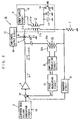
- Fig. 1 is a circuit diagram showing an exemplary structure of a deflection system according to a first embodiment of the present invention.
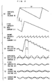
- Figs. 2(a) to 2(h) are waveform diagrams for illustrating operations of the deflection system shown in Fig. 1.
- Fig. 3 is a circuit diagram showing an exemplary structure of a deflection system according to a second embodiment of the present invention.
- Figs. 4(a) to 4(d) are waveform diagrams for illustrating operations in a horizontal reciprocating deflection mode.
- Figs. 5(a) and 5(b) are conceptual diagrams showing scanning in the horizontal reciprocating deflection mode.
- FIG. 1 is a circuit diagram showing an exemplary structure of the deflection system 1A according to the first embodiment.
- the deflection system 1A shown in Fig. 1 comprises a sawtooth wave voltage generation circuit 2, an amplifier 3, a vertical deflection coil 4, a transformer 17, a resistor 7, a feedback circuit 8, a current supply circuit 5, a horizontal output circuit 15, a horizontal deflection coil 16, an amplitude regulating circuit 30, a phase regulating circuit 31 and an addition circuit 34.
- the current supply circuit 5 includes a power supply circuit 10, a transformer 11, a capacitor 12, a diode 13 and a switch 14.
- a first input terminal of the addition circuit 34 is connected to an output terminal of the sawtooth wave voltage generation circuit 2.
- An input terminal of the amplifier 3 is connected to an output terminal of the addition circuit 34.
- the vertical deflection coil 4, a secondary winding 11b of the transformer 11 and the resistor 7 are serially connected between an output terminal of the amplifier 3 and a ground terminal.
- the node between the secondary winding 11b of the transformer 11 and the resistor 7 is connected to a second input terminal of the addition circuit 34 through the feedback circuit 8.
- the horizontal deflection coil 16 and a primary winding 17a of the transformer 17 are serially connected between an output terminal of the horizontal output circuit 15 and a ground terminal.
- the amplitude regulating circuit 30 is connected to a secondary winding 17b of the transformer 17, and an output terminal of the amplitude regulating circuit 30 is connected to a third input terminal of the addition circuit 34 through the phase regulating circuit 31.
- a first end of a primary winding 11a of the transformer 11 is connected to an output terminal of the power supply circuit 10.
- the capacitor 12, the diode 13 and the switch 14 are connected in parallel with each other between a second end of the primary winding 11a of the transformer 11 and a ground terminal.
- the sawtooth wave voltage generation circuit 2 generates a sawtooth wave voltage SV shown in Fig. 2(a) and outputs the same to the input terminal of the amplifier 3 through the addition circuit 34 in synchronization with a vertical synchronizing signal VS.
- the cycle of the sawtooth wave voltage SV corresponds to one vertical scanning period V.
- the amplifier 3 supplies a first sawtooth wave current SI1 shown in Fig. 2(b) to the vertical deflection coil 4 in response to the sawtooth wave voltage SV generated by the sawtooth wave voltage generation circuit 2.
- the first sawtooth wave current SI1 supplied by the amplifier 3 lags the sawtooth wave voltage SV by a phase difference of about 90° (V/4), as shown in Figs. 2(a) and 2(b) respectively.
- the power supply circuit 10 of the current supply circuit 5 applies a power supply voltage to the first end of the primary winding 11a of the transformer 11.
- the switch 14 is turned on/off in synchronization with a horizontal synchronizing signal HS, thereby feeding a charge/discharge current to the capacitor 12 and the diode 13.
- the vertical deflection coil 4 is supplied with a second sawtooth wave current SI2 shown in Fig. 2(c) through the transformer 11.
- the first sawtooth wave current SI1 and the second sawtooth wave current SI2 are composited with each other to obtain a vertical deflection current VI shown in Fig. 2(d).
- the vertical deflection coil 4 generates a vertical deflection magnetic field by the vertical deflection current VI and vertically deflects an electron beam.
- the feedback circuit 8 generates a negative feedback voltage on the basis of the vertical deflection current VI and supplies the negative feedback voltage to the input terminal of the amplifier 3 through the addition circuit 34, thereby correcting nonlinear distortion of the first sawtooth wave current SI1.
- the horizontal output circuit 15 supplies a horizontal deflection current HI shown in Fig. 2(e) to the horizontal deflection coil 16.
- the frequency of the horizontal deflection current HI is half a horizontal scanning frequency due to reciprocating scanning.
- the horizontal deflection coil 16 generates a horizontal deflection magnetic field by the horizontal deflection current HI and horizontally deflects the electron beam in a reciprocating manner.
- the horizontal deflection current HI flowing in the horizontal deflection coil 16 induces a current component to the vertical deflection coil 4. Consequently, the vertical deflection current VI is distorted as shown by broken lines in Fig. 2(d).
- a voltage responsive to the horizontal deflection current HI flowing in the primary winding 17a of the transformer 17 is generated on the secondary winding 17b of the transformer 17.
- the amplitude regulating circuit 30 regulates the amplitude of the voltage developed across the secondary winding 17b of the transformer 17, and outputs the regulated voltage to the phase regulating circuit 31 as a first correction voltage AV1 shown in Fig. 2(f).
- the first correction voltage AV1 leads the horizontal deflection current HI by a phase difference of 90°.
- the phase regulating circuit 31 regulates the phase of the first correction voltage AV1 output from the amplitude regulating circuit 30 and outputs the regulated voltage as a second correction voltage AV2 shown in Fig. 2(g).
- the amplitude regulating circuit 30 shifts the phase of the first correction voltage AV1 by 180° and supplies the phase-shifted voltage to the addition circuit 34 as the second correction voltage AV2.
- the addition circuit 34 supplies a voltage obtained by adding the sawtooth wave voltage SV generated by the sawtooth wave voltage generation circuit 2, the negative feedback voltage generated by the feedback circuit 8 and the second correction voltage AV2 output from the phase regulating circuit 31 to each other to the input terminal of the amplifier 3.
- a correction current shown in Fig. 2(h) responsive to the second sawtooth wave voltage AV2 is added to the first sawtooth wave current SI1 output from the amplifier 3.
- the correction current supplied by the amplifier 3 lags the second correction voltage AV2 by a phase difference of 90°, as shown in Fig. 2(h).
- the correction current is regulated by the amplitude regulating circuit 30 and the phase regulating circuit 31 to be of opposite polarity to and of the same magnitude as the current component induced to the vertical deflection coil 4 by the horizontal deflection current HI of the horizontal deflection coil 16. Therefore, the current induced to the vertical deflection coil 4 by the horizontal deflection current HI is canceled by the correction circuit. Consequently, the distortion of the vertical deflection current VI shown by the broken lines in Fig. 2(d) is corrected to that shown by solid lines.
- the correction current supplied by the amplifier 3 in correspondence to the second correction voltage AV2 output from the phase regulating circuit 31 can cancel the current component induced to the vertical deflection coil 4 by the horizontal deflection current HI of the horizontal deflection coil 16 in response to the horizontal deflection current HI detected by the transformer 17.
- the correction voltage AV2 is added to the vertical deflection voltage SV in front of the amplifier 3, to require neither a large-capacity transformer nor a driving circuit for adding the correction current to the vertical deflection current VI. Consequently, the cost as well as power consumption can be reduced.
- the horizontal output circuit 15 corresponds to the horizontal deflection current supply circuit
- the transformer 17 corresponds to the induced current detection circuit as well as the horizontal deflection current detection circuit
- the amplitude regulating circuit 30 and the phase regulating circuit 31 correspond to the regulating circuit
- the amplitude regulating circuit 30, the phase regulating circuit 31 and the addition circuit 34 correspond to the correction voltage addition circuit
- the amplifier 3 corresponds to the first current supply circuit
- the current supply circuit 5 corresponds to the second current supply circuit.
- FIG. 3 is a circuit diagram showing an exemplary structure of the deflection system 1B according to the second embodiment.
- the deflection system 1B shown in Fig. 3 comprises a sawtooth wave voltage generation circuit 2, an amplifier 3, a vertical deflection coil 4, a current supply circuit 5, a resistor 7, a feedback circuit 8, a horizontal output circuit 15, a horizontal deflection coil 16, an amplitude regulating circuit 30, a phase regulating circuit 31, a capacitor 32, a transformer 33 and an addition circuit 34.
- the deflection system 1B according to the second embodiment is different from the deflection system 1A according to the first embodiment in a point that, while the transformer 1A detects the current component induced to the vertical deflection coil 4 by the horizontal deflection current HI of the horizontal deflection coil 16 from the horizontal deflection current HI with the transformer 17, the deflection system 1B extracts and detects the current component from a vertical deflection current VI.
- the deflection system 1B comprises the capacitor 32 and the transformer 33 in place of the transformer 17.
- the deflection system 1B is different from the deflection system 1A only in a detection circuit for detecting the current component induced to the vertical deflection coil 4 by a horizontal deflection current HI of the horizontal deflection coil 16, and the remaining structure thereof is identical to that of the deflection system 1A.
- Fig. 3 parts identical or corresponding to those in Fig. 1 are denoted by the same reference numerals.
- the detection circuit for detecting the current component induced to the vertical deflection coil 4 by the horizontal deflection current HI is now described.
- the capacitor 32 and a primary winding 33a of the transformer 33 are serially connected with each other, so that the capacitor 32 and the transformer 33 form a first serially connected body.
- the vertical deflection coil 4 and a secondary winding 11b of a transformer 11 are serially connected with each other, so that the vertical deflection coil 4 and the transformer 11 form a second serially connected body.
- the first and second serially connected bodies are connected in parallel with each other to form a resonance circuit.
- the first and second serially connected bodies form the resonance circuit, and hence a resonance current flows in a loop formed by the vertical deflection coil 4, the transformers 11 and 33 and the capacitor 32.
- the resonance current flowing in this loop is so regulated as to have a frequency half a horizontal scanning frequency.
- the resonance current has the same frequency as the current component induced to the vertical deflection coil 4 by the horizontal deflection current HI of the horizontal deflection coil 16. Therefore, a voltage responsive to the current component induced to the vertical deflection coil 4 by the horizontal deflection current HI of the horizontal deflection coil 16 is generated on a secondary winding 33b of the transformer 33.
- the amplitude regulating circuit 30 regulates the amplitude of the voltage developed across the secondary winding 33b of the transformer 33 and outputs the first correction voltage AV1 shown in Fig. 2(f), while the phase regulating circuit 31 regulates the phase of the first correction voltage AV1 output from the amplitude regulating circuit 30 and outputs the second correction voltage AV2 shown in Fig. 2(g).
- the current component induced to the vertical deflection coil 4 by the horizontal deflection current HI of the horizontal deflection coil 16 is canceled similarly to the deflection system 1A according to the first embodiment.
- the resonance current flowing in the transformer 33 is smaller than the vertical deflection current VI, and hence the transformer 33 can be prepared from that of a small capacity. Also in this embodiment, therefore, the cost and power consumption can be reduced.
- the correction current supplied by the amplifier 3 in correspondence to the second correction voltage AV2 output from the phase regulating circuit 31 can cancel the current component induced to the vertical deflection coil 4 by the horizontal deflection current HI of the horizontal deflection coil 16 in response to the current component detected by the capacitor 32 and the transformer 33.
- the capacitor 32 and the transformer 33 correspond to the induced current detection circuit, and the transformer 33 corresponds to the resonance current detection circuit.
Landscapes
- Engineering & Computer Science (AREA)
- Multimedia (AREA)
- Signal Processing (AREA)
- Details Of Television Scanning (AREA)
Abstract
A primary winding of a transformer is serially connected
to a horizontal deflection coil. An amplitude regulating
circuit outputs a first correction voltage in response to a
voltage generated on a secondary winding of the transformer.
A phase regulating circuit regulates the phase of the first
correction voltage output from the amplitude regulating
circuit and outputs a second correction voltage. An addition
circuit adds the second correction voltage to a sawtooth wave
voltage generated by a sawtooth wave voltage generation circuit.
A correction current output from an amplifier in response to
the second correction voltage output from the phase regulating
circuit cancels a current component generated on a vertical
deflection coil by a horizontal deflection current.
Description
The present invention relates to a deflection system and
a deflection method of a horizontal reciprocating deflection
mode scanning an electron beam in a reciprocating manner.
A deflection system of a horizontal reciprocating
deflection mode scanning an electron beam in a reciprocating
manner is recently proposed in the field of a display unit for
a television set or the like, in order to make display of a
high resolution. In the deflection system of the horizontal
reciprocating deflection mode, a forward scanning line and a
backward scanning line must be parallelized with each other.
Figs. 4(a) to 4(d) are waveform diagrams for illustrating
a vertical deflection current and a horizontal deflection
current employed in the horizontal reciprocating deflection
mode for parallelizing forward and backward scanning lines with
each other. Fig. 4(a) shows a first sawtooth wave current SI1
for generating a vertical deflection magnetic field moving an
electron beam from the top to the bottom of a screen of a
television set or the like and thereafter returning the
electron beam to the top of the screen again. When performing
reciprocating scanning with the first sawtooth wave current
SI1 shown in Fig. 4(a), the forward and backward scanning lines
are not parallelized with each other. Therefore, inclination
of a vertical deflection current must be nulled in forward
scanning and backward scanning in order to parallelize the
forward and backward scanning lines with each other.
Therefore, a second sawtooth wave current SI2 shown in
Fig. 4(b) is added to the first sawtooth wave current SI1 shown
in Fig. 4(a), for generating a vertical deflection current VI
shown in Fig. 4(c). The second sawtooth wave current SI2 shown
in Fig. 4(b) has the same frequency as a horizontal scanning
frequency, and the inclination of the second sawtooth wave
current SI2 in forward scanning and backward scanning is so
set that inclination of the composited vertical deflection
current VI in forward scanning and backward scanning is nulled.
A horizontal deflection current HI shown in Fig. 4(d)
has the waveform of a frequency half the horizontal scanning
frequency for performing reciprocating scanning.
Figs. 5(a) and 5(b) are conceptual diagrams showing
parallelized reciprocating deflection scanning. When
performing reciprocating scanning with the vertical deflection
current VI shown in Fig. 4(c) and the horizontal deflection
current HI shown in Fig. 4(d), such ideal reciprocating
scanning that a scanning line 21 performs reciprocating
scanning in parallel on a screen 20 is implemented as shown
in Fig. 5(a). When supplying the vertical deflection current
VI shown in Fig. 4(c) to a vertical deflection coil while
supplying the horizontal deflection current HI shown in Fig.
4(d) to a horizontal deflection coil, however, the scanning
line may be distorted. When a current component resulting from
the horizontal deflection current HI is induced from the
horizontal deflection coil to the vertical deflection coil and
superposed on the vertical deflection current VI shown in Fig.
4(c), a scanning line 22 is distorted as shown in Fig. 5(b),
to distort a displayed image.
In a conventional deflection system, the following
method, for example, is carried out in order to cancel a current
component induced to flow in a vertical deflection coil from
a horizontal deflection coil by a horizontal deflection
current: A transformer is serially connected to the vertical
deflection coil for supplying the vertical deflection coil with
a current 180° out of phase with the horizontal deflection
current flowing in the horizontal deflection coil through the
transformer. Thus, the current component induced to the
vertical deflection coil is canceled. In this case, the
transformer serially connected to the vertical deflection coil
must be of a standard suitable to the large vertical deflection
current, and hence the manufacturing cost is increased.
Further, power consumed in a driving circuit for driving the
transformer is disadvantageously increased.
An object of the present invention is to provide a
deflection system and a deflection method capable of performing
reciprocating deflection without distorting a scanning line
and reducing the cost as well as power consumption.
A deflection system according to an aspect of the present
invention, performing reciprocating scanning by horizontally
deflecting an electron beam in a reciprocating manner in
response to a vertical synchronizing signal and a horizontal
synchronizing signal, comprises a vertical deflection coil,
a horizontal deflection coil, a horizontal deflection current
supply circuit supplying a horizontal deflection current for
horizontally deflecting the electron beam in a reciprocating
manner, an induced current detection circuit detecting a
current component induced to the vertical deflection coil by
the horizontal deflection current flowing in the horizontal
deflection coil, a sawtooth wave voltage generation circuit
generating a sawtooth wave voltage synchronous with the
vertical synchronizing signal, a first current supply circuit
receiving the sawtooth wave voltage generated by the sawtooth
wave voltage generation circuit and supplying a first sawtooth
wave current for vertically deflecting the electron beam to
the vertical deflection coil, a second current supply circuit
supplying a second sawtooth wave current for parallelizing
forward and backward scanning lines with each other to the
vertical deflection coil, and a correction voltage addition
circuit adding a correction voltage for canceling the current
component detected by the induced current detection circuit
to the sawtooth wave voltage generated by the sawtooth wave
voltage generation circuit.
In the deflection system, the induced current detection
circuit detects the current component induced to the vertical
deflection coil by the horizontal deflection current flowing
in the horizontal deflection coil. The correction voltage
addition circuit adds the correction voltage to the sawtooth
wave voltage on the basis of the detected current component,
and the first current supply circuit supplies the current
component responsive to the correction voltage to the vertical
deflection coil.
Thus, the current component induced to the vertical
deflection coil by the horizontal deflection current flowing
in the horizontal deflection coil can be canceled. Therefore,
reciprocating deflection can be performed without distorting
the scanning lines. In this case, no transformer may be
serially connected to the vertical deflection coil for
supplying a current component for canceling the current
component induced to the vertical deflection coil. Therefore,
the cost for the deflection system as well as power consumption
can be reduced.
The induced current detection circuit may generate an
output voltage responsive to the current component, and the
correction voltage addition circuit may include a regulating
circuit regulating the amplitude and the phase of the output
voltage from the induced current detection circuit and
outputting the regulated output voltage as the correction
voltage and an addition circuit adding the correction voltage
output from the regulating circuit to the sawtooth wave voltage
generated by the sawtooth wave voltage generation circuit.
In this case, the induced current detection circuit
generates the output voltage responsive to the current
component induced to the vertical deflection coil, while the
regulating circuit regulates the amplitude and the phase of
the output voltage and outputs the correction voltage having
proper relation to the phase of the current component induced
to the vertical deflection coil. Further, the addition circuit
adds the correction voltage to the sawtooth wave voltage
generated by the sawtooth wave voltage generation circuit.
Thus, the first current supply circuit supplies a current
component of opposite polarity to the current component induced
to the vertical deflection coil to the vertical deflection coil
in response to the correction voltage. Consequently, the
current component induced to the vertical deflection coil can
be canceled by the current component supplied from the first
current supply circuit.
The induced current detection circuit may include a
horizontal deflection current detection circuit detecting the
current component induced to the vertical deflection coil by
the horizontal deflection current flowing in the horizontal
deflection coil from the horizontal deflection current.
In this case, the horizontal deflection current
detection circuit detects the current component induced to the
vertical deflection coil from the horizontal deflection
current. Thus, the induced current component can be more
readily detected as compared with the case of extracting the
induced current component from the vertical deflection
current.
The horizontal deflection current detection circuit may
include a first transformer having a primary winding serially
connected to the horizontal deflection coil and a secondary
winding connected to the correction voltage addition circuit.
In this case, the horizontal deflection current is
smaller than the vertical deflection current and hence the
current component induced to the vertical deflection coil can
be detected with a smaller transformer as compared with the
case of inserting a transformer serially to the vertical
deflection coil. Thus, the cost can be further reduced.
The correction voltage addition circuit may include a
regulating circuit regulating the amplitude and the phase of
an output voltage from the secondary winding of the first
transformer and outputting the regulated output voltage as the
correction voltage and an addition circuit adding the
correction voltage output from the regulating circuit to the
sawtooth wave voltage generated by the sawtooth wave voltage
generation circuit.
In this case, the regulating circuit regulates the
amplitude and the phase of the output voltage from the secondary
winding of the first transformer and outputs the regulated
voltage as the correction voltage, while the addition circuit
adds the correction voltage to the sawtooth wave voltage.
The second current supply circuit may include a second
transformer having a primary winding and a secondary winding
serially connected to the vertical deflection coil and a
sawtooth wave current supply circuit supplying a sawtooth wave
current synchronous with the horizontal synchronizing signal
to the primary winding of the second transformer.
In this case, the primary winding of the second
transformer is supplied with the sawtooth wave current
synchronous with the horizontal synchronizing signal, and the
secondary winding supplies the second sawtooth wave current
to the vertical deflection coil.
The deflection system may further comprise a feedback
circuit negatively feeding back a voltage on an end of the second
winding of the second transformer to the correction voltage
addition circuit, and the addition circuit may add the voltage
negatively fed back by the feedback circuit to the correction
voltage and the sawtooth wave voltage.
In this case, the voltage on the end of the secondary
winding of the second transformer is negatively fed back to
the correction voltage addition circuit, while the addition
circuit adds the negatively fed-back voltage to the correction
voltage and the sawtooth wave voltage.
The induced current detection circuit may include a
resonance circuit resonating at a frequency substantially half
a horizontal scanning frequency and a resonance current
detection circuit detecting a current flowing in the resonance
circuit by resonance.
The frequency of the current component induced to the
vertical deflection coil by the horizontal deflection current
is half the horizontal scanning frequency. Therefore, the
current component induced to the vertical deflection coil by
the horizontal deflection current can be directly detected by
detecting the current flowing in the resonance circuit
resonating at the frequency substantially half the horizontal
scanning frequency.
The induced current detection circuit may include a
capacitor and a first transformer having a primary winding
serially connected to the capacitor and a secondary winding
connected to the correction voltage addition circuit, the
resonance circuit may be formed by the primary winding of the
first transformer, the capacitor and the vertical deflection
coil, and the resonance current detection circuit may be formed
by the secondary winding of the first transformer.
In this case, the primary winding of the first transformer,
the capacitor and the vertical deflection coil form the
resonance circuit, and the resonance current detection circuit
formed by the secondary winding of the first transformer
detects the current flowing in the resonance circuit. The
current flowing in the resonance circuit is smaller than the
vertical deflection current, and hence the current component
induced to the vertical deflection coil can be detected with
a smaller transformer as compared with the case of inserting
a transformer serially to the vertical deflection coil. Thus,
the cost can be further reduced.
The correction voltage addition circuit may include a
regulating circuit regulating the amplitude and the phase of
an output voltage from the secondary winding of the first
transformer and outputting the regulated output voltage as the
correction voltage and an addition circuit adding the
correction voltage output from the regulating circuit to the
sawtooth wave voltage generated by the sawtooth wave voltage
generation circuit.
In this case, the regulating circuit regulates the
amplitude and the phase of the output voltage from the secondary
winding of the first transformer and outputs the regulated
voltage as the correction voltage, while the addition circuit
adds the correction voltage to the sawtooth wave voltage.
The second current supply circuit may include a second
transformer having a primary winding and a secondary winding
serially connected to the vertical deflection coil and a
sawtooth wave current supply circuit supplying a sawtooth wave
current synchronous with the horizontal synchronizing signal
to the secondary winding of the second transformer, and the
resonance circuit may be formed by the primary winding of the
first transformer, the capacitor, the vertical deflection coil
and the secondary winding of the second transformer.
In this case, the primary winding of the first transformer,
the capacitor, the vertical deflection coil and the secondary
winding of the second transformer form the resonance circuit,
and the resonance current detection circuit formed by the
secondary winding of the first transformer detects the current
flowing in the resonance circuit. The current flowing in the
resonance circuit is smaller than the vertical deflection
current, and hence the current component induced to the
vertical deflection coil can be detected with a smaller
transformer as compared the case of inserting a transformer
serially to the vertical deflection coil. Thus, the cost can
be further reduced.
The deflection system may further comprise a feedback
circuit negatively feeding back a voltage on an end of the
secondary winding of the second transformer to the correction
voltage addition circuit, and the addition circuit may add the
voltage negatively fed back by the feedback circuit to the
correction voltage and the sawtooth wave voltage.
In this case, the voltage on the end of the secondary
winding of the second transformer is negatively fed back to
the correction voltage addition circuit, and the addition
circuit adds the negatively fed-back voltage to the correction
voltage and the sawtooth wave voltage.
The first current supply circuit may include an amplifier.
In this case, a current based on the sawtooth wave voltage and
the correction voltage added to each other by the addition
circuit is supplied to the vertical deflection coil.
A deflection method according to another aspect of the
present invention, performing reciprocating scanning by
horizontally deflecting an electron beam in a reciprocating
manner in response to a vertical synchronizing signal and a
horizontal synchronizing signal in a deflection system
comprising a vertical deflection coil and a horizontal
deflection coil, comprises steps of supplying a horizontal
deflection current for horizontally deflecting the electron
beam in a reciprocating manner to the horizontal deflection
coil, detecting a current component induced to the vertical
deflection coil by a horizontal deflection current flowing in
the horizontal deflection coil, generating a sawtooth wave
voltage synchronous with the vertical synchronizing signal,
receiving the sawtooth wave voltage and supplying a first
sawtooth wave current for vertically deflecting the electron
beam to the vertical deflection coil, supplying a second
sawtooth wave current for parallelizing forward and backward
scanning lines with each other to the vertical deflection coil
and adding a correction voltage for canceling the detected
current component to the generated sawtooth wave voltage.
According to this deflection method, the current
component induced to the vertical deflection coil by the
horizontal deflection current flowing in the horizontal
deflection coil is detected. The correction voltage is added
to the sawtooth wave voltage on the basis of the detected current
component, and the current component responsive to the
correction voltage is supplied to the vertical deflection coil.
Thus, the current component induced to the vertical
deflection coil by the horizontal deflection current flowing
in the horizontal deflection coil can be canceled. Therefore,
reciprocating deflection can be performed without distorting
the scanning lines. In this case, no transformer may be
serially connected to the vertical deflection coil in order
to supply a current component for canceling the current
component induced to the vertical deflection coil. Therefore,
the cost for the deflection system as well as power consumption
can be reduced.
The step of detecting the current component may include
a step of detecting the current component induced to the
vertical deflection coil by the horizontal deflection current
flowing in the horizontal deflection coil from the horizontal
deflection current.
In this case, the current component induced to the
vertical deflection coil is detected from the horizontal
deflection current. Thus, the induced current component can
be more readily detected as compared with the case of extracting
the induced current component from the vertical deflection
current.
The step of detecting the current component may include
steps of generating a current resonating at a frequency
substantially half a horizontal scanning frequency and
detecting the resonating current.
The frequency of the current component induced to the
vertical deflection coil by the horizontal deflection current
is half the horizontal scanning frequency. Therefore, the
current component induced to the vertical deflection coil by
the horizontal deflection current can be directly detected by
detecting the current resonating at a frequency substantially
half the horizontal scanning frequency.
Fig. 1 is a circuit diagram showing an exemplary structure
of a deflection system according to a first embodiment of the
present invention.
Figs. 2(a) to 2(h) are waveform diagrams for illustrating
operations of the deflection system shown in Fig. 1.
Fig. 3 is a circuit diagram showing an exemplary structure
of a deflection system according to a second embodiment of the
present invention.
Figs. 4(a) to 4(d) are waveform diagrams for illustrating
operations in a horizontal reciprocating deflection mode.
Figs. 5(a) and 5(b) are conceptual diagrams showing
scanning in the horizontal reciprocating deflection mode.
A deflection system 1A according to a first embodiment
of the present invention is now described with reference to
Fig. 1. Fig. 1 is a circuit diagram showing an exemplary
structure of the deflection system 1A according to the first
embodiment.
The deflection system 1A shown in Fig. 1 comprises a
sawtooth wave voltage generation circuit 2, an amplifier 3,
a vertical deflection coil 4, a transformer 17, a resistor 7,
a feedback circuit 8, a current supply circuit 5, a horizontal
output circuit 15, a horizontal deflection coil 16, an
amplitude regulating circuit 30, a phase regulating circuit
31 and an addition circuit 34. The current supply circuit 5
includes a power supply circuit 10, a transformer 11, a
capacitor 12, a diode 13 and a switch 14.
A first input terminal of the addition circuit 34 is
connected to an output terminal of the sawtooth wave voltage
generation circuit 2. An input terminal of the amplifier 3
is connected to an output terminal of the addition circuit 34.
The vertical deflection coil 4, a secondary winding 11b of the
transformer 11 and the resistor 7 are serially connected
between an output terminal of the amplifier 3 and a ground
terminal. The node between the secondary winding 11b of the
transformer 11 and the resistor 7 is connected to a second input
terminal of the addition circuit 34 through the feedback
circuit 8.
The horizontal deflection coil 16 and a primary winding
17a of the transformer 17 are serially connected between an
output terminal of the horizontal output circuit 15 and a ground
terminal. The amplitude regulating circuit 30 is connected
to a secondary winding 17b of the transformer 17, and an output
terminal of the amplitude regulating circuit 30 is connected
to a third input terminal of the addition circuit 34 through
the phase regulating circuit 31.
A first end of a primary winding 11a of the transformer
11 is connected to an output terminal of the power supply circuit
10. The capacitor 12, the diode 13 and the switch 14 are
connected in parallel with each other between a second end of
the primary winding 11a of the transformer 11 and a ground
terminal.
Operations of the deflection system 1A shown in Fig. 1
are now described with reference to waveform diagrams of Figs.
2(a) to 2(h).
The sawtooth wave voltage generation circuit 2 generates
a sawtooth wave voltage SV shown in Fig. 2(a) and outputs the
same to the input terminal of the amplifier 3 through the
addition circuit 34 in synchronization with a vertical
synchronizing signal VS. The cycle of the sawtooth wave
voltage SV corresponds to one vertical scanning period V.
The amplifier 3 supplies a first sawtooth wave current
SI1 shown in Fig. 2(b) to the vertical deflection coil 4 in
response to the sawtooth wave voltage SV generated by the
sawtooth wave voltage generation circuit 2. The first sawtooth
wave current SI1 supplied by the amplifier 3 lags the sawtooth
wave voltage SV by a phase difference of about 90° (V/4), as
shown in Figs. 2(a) and 2(b) respectively.
The power supply circuit 10 of the current supply circuit
5 applies a power supply voltage to the first end of the primary
winding 11a of the transformer 11. The switch 14 is turned
on/off in synchronization with a horizontal synchronizing
signal HS, thereby feeding a charge/discharge current to the
capacitor 12 and the diode 13. Thus, the vertical deflection
coil 4 is supplied with a second sawtooth wave current SI2 shown
in Fig. 2(c) through the transformer 11.
The first sawtooth wave current SI1 and the second
sawtooth wave current SI2 are composited with each other to
obtain a vertical deflection current VI shown in Fig. 2(d).
The vertical deflection coil 4 generates a vertical deflection
magnetic field by the vertical deflection current VI and
vertically deflects an electron beam.
The vertical deflection current VI shown in Fig. 2(d),
remarkably changing at the turn between forward scanning and
backward scanning, remains constant in forward scanning and
backward scanning. As shown in Fig. 5(a), therefore, the
scanning line 21 is horizontal on the screen 20. Referring
to Fig. 2(d), symbol H denotes one horizontal scanning period.
The feedback circuit 8 generates a negative feedback
voltage on the basis of the vertical deflection current VI and
supplies the negative feedback voltage to the input terminal
of the amplifier 3 through the addition circuit 34, thereby
correcting nonlinear distortion of the first sawtooth wave
current SI1.
The horizontal output circuit 15 supplies a horizontal
deflection current HI shown in Fig. 2(e) to the horizontal
deflection coil 16. The frequency of the horizontal deflection
current HI is half a horizontal scanning frequency due to
reciprocating scanning. The horizontal deflection coil 16
generates a horizontal deflection magnetic field by the
horizontal deflection current HI and horizontally deflects the
electron beam in a reciprocating manner. At this time, the
horizontal deflection current HI flowing in the horizontal
deflection coil 16 induces a current component to the vertical
deflection coil 4. Consequently, the vertical deflection
current VI is distorted as shown by broken lines in Fig. 2(d).
A voltage responsive to the horizontal deflection
current HI flowing in the primary winding 17a of the transformer
17 is generated on the secondary winding 17b of the transformer
17. The amplitude regulating circuit 30 regulates the
amplitude of the voltage developed across the secondary winding
17b of the transformer 17, and outputs the regulated voltage
to the phase regulating circuit 31 as a first correction voltage
AV1 shown in Fig. 2(f). The first correction voltage AV1 leads
the horizontal deflection current HI by a phase difference of
90°.
The phase regulating circuit 31 regulates the phase of
the first correction voltage AV1 output from the amplitude
regulating circuit 30 and outputs the regulated voltage as a
second correction voltage AV2 shown in Fig. 2(g). For example.
the amplitude regulating circuit 30 shifts the phase of the
first correction voltage AV1 by 180° and supplies the
phase-shifted voltage to the addition circuit 34 as the second
correction voltage AV2.
Finally, the addition circuit 34 supplies a voltage
obtained by adding the sawtooth wave voltage SV generated by
the sawtooth wave voltage generation circuit 2, the negative
feedback voltage generated by the feedback circuit 8 and the
second correction voltage AV2 output from the phase regulating
circuit 31 to each other to the input terminal of the amplifier
3. Thus, a correction current shown in Fig. 2(h) responsive
to the second sawtooth wave voltage AV2 is added to the first
sawtooth wave current SI1 output from the amplifier 3. The
correction current supplied by the amplifier 3 lags the second
correction voltage AV2 by a phase difference of 90°, as shown
in Fig. 2(h). The correction current is regulated by the
amplitude regulating circuit 30 and the phase regulating
circuit 31 to be of opposite polarity to and of the same
magnitude as the current component induced to the vertical
deflection coil 4 by the horizontal deflection current HI of
the horizontal deflection coil 16. Therefore, the current
induced to the vertical deflection coil 4 by the horizontal
deflection current HI is canceled by the correction circuit.
Consequently, the distortion of the vertical deflection
current VI shown by the broken lines in Fig. 2(d) is corrected
to that shown by solid lines.
In the deflection system 1A according to this embodiment,
as hereinabove described, the correction current supplied by
the amplifier 3 in correspondence to the second correction
voltage AV2 output from the phase regulating circuit 31 can
cancel the current component induced to the vertical deflection
coil 4 by the horizontal deflection current HI of the horizontal
deflection coil 16 in response to the horizontal deflection
current HI detected by the transformer 17.
In this case, the correction voltage AV2 is added to the
vertical deflection voltage SV in front of the amplifier 3,
to require neither a large-capacity transformer nor a driving
circuit for adding the correction current to the vertical
deflection current VI. Consequently, the cost as well as power
consumption can be reduced.
In the embodiment, the horizontal output circuit 15
corresponds to the horizontal deflection current supply
circuit, the transformer 17 corresponds to the induced current
detection circuit as well as the horizontal deflection current
detection circuit, the amplitude regulating circuit 30 and the
phase regulating circuit 31 correspond to the regulating
circuit, the amplitude regulating circuit 30, the phase
regulating circuit 31 and the addition circuit 34 correspond
to the correction voltage addition circuit, the amplifier 3
corresponds to the first current supply circuit, and the
current supply circuit 5 corresponds to the second current
supply circuit.
A deflection system 1B according to a second embodiment
of the present invention is now described with reference to
Fig. 3. Fig. 3 is a circuit diagram showing an exemplary
structure of the deflection system 1B according to the second
embodiment.
The deflection system 1B shown in Fig. 3 comprises a
sawtooth wave voltage generation circuit 2, an amplifier 3,
a vertical deflection coil 4, a current supply circuit 5, a
resistor 7, a feedback circuit 8, a horizontal output circuit
15, a horizontal deflection coil 16, an amplitude regulating
circuit 30, a phase regulating circuit 31, a capacitor 32, a
transformer 33 and an addition circuit 34.
The deflection system 1B according to the second
embodiment is different from the deflection system 1A according
to the first embodiment in a point that, while the transformer
1A detects the current component induced to the vertical
deflection coil 4 by the horizontal deflection current HI of
the horizontal deflection coil 16 from the horizontal
deflection current HI with the transformer 17, the deflection
system 1B extracts and detects the current component from a
vertical deflection current VI.
Therefore, the deflection system 1B comprises the
capacitor 32 and the transformer 33 in place of the transformer
17. In other words, the deflection system 1B is different from
the deflection system 1A only in a detection circuit for
detecting the current component induced to the vertical
deflection coil 4 by a horizontal deflection current HI of the
horizontal deflection coil 16, and the remaining structure
thereof is identical to that of the deflection system 1A.
Referring to Fig. 3, parts identical or corresponding to those
in Fig. 1 are denoted by the same reference numerals.
The detection circuit for detecting the current
component induced to the vertical deflection coil 4 by the
horizontal deflection current HI is now described. The
capacitor 32 and a primary winding 33a of the transformer 33
are serially connected with each other, so that the capacitor
32 and the transformer 33 form a first serially connected body.
The vertical deflection coil 4 and a secondary winding 11b of
a transformer 11 are serially connected with each other, so
that the vertical deflection coil 4 and the transformer 11 form
a second serially connected body. The first and second
serially connected bodies are connected in parallel with each
other to form a resonance circuit.
The first and second serially connected bodies form the
resonance circuit, and hence a resonance current flows in a
loop formed by the vertical deflection coil 4, the transformers
11 and 33 and the capacitor 32. The resonance current flowing
in this loop is so regulated as to have a frequency half a
horizontal scanning frequency. Thus, the resonance current
has the same frequency as the current component induced to the
vertical deflection coil 4 by the horizontal deflection current
HI of the horizontal deflection coil 16. Therefore, a voltage
responsive to the current component induced to the vertical
deflection coil 4 by the horizontal deflection current HI of
the horizontal deflection coil 16 is generated on a secondary
winding 33b of the transformer 33.
The amplitude regulating circuit 30 regulates the
amplitude of the voltage developed across the secondary winding
33b of the transformer 33 and outputs the first correction
voltage AV1 shown in Fig. 2(f), while the phase regulating
circuit 31 regulates the phase of the first correction voltage
AV1 output from the amplitude regulating circuit 30 and outputs
the second correction voltage AV2 shown in Fig. 2(g). Thus,
the current component induced to the vertical deflection coil
4 by the horizontal deflection current HI of the horizontal
deflection coil 16 is canceled similarly to the deflection
system 1A according to the first embodiment.
In this case, the resonance current flowing in the
transformer 33 is smaller than the vertical deflection current
VI, and hence the transformer 33 can be prepared from that of
a small capacity. Also in this embodiment, therefore, the cost
and power consumption can be reduced.
In the deflection system 1B according to this embodiment,
the correction current supplied by the amplifier 3 in
correspondence to the second correction voltage AV2 output from
the phase regulating circuit 31 can cancel the current
component induced to the vertical deflection coil 4 by the
horizontal deflection current HI of the horizontal deflection
coil 16 in response to the current component detected by the
capacitor 32 and the transformer 33.
In the second embodiment, the capacitor 32 and the
transformer 33 correspond to the induced current detection
circuit, and the transformer 33 corresponds to the resonance
current detection circuit.
Claims (16)
- A deflection system performing reciprocating scanning by horizontally deflecting an electron beam in a reciprocating manner in response to a vertical synchronizing signal and a horizontal synchronizing signal, comprising:a vertical deflection coil;a horizontal deflection coil;a horizontal deflection current supply circuit supplying a horizontal deflection current for horizontally deflecting said electron beam in a reciprocating manner;an induced current detection circuit detecting a current component induced to said vertical deflection coil by said horizontal deflection current flowing in said horizontal deflection coil;a sawtooth wave voltage generation circuit generating a sawtooth wave voltage synchronous with said vertical synchronizing signal;a first current supply circuit receiving said sawtooth wave voltage generated by said sawtooth wave voltage generation circuit and supplying a first sawtooth wave current for vertically deflecting said electron beam to said vertical deflection coil;a second current supply circuit supplying a second sawtooth wave current for parallelizing forward and backward scanning lines with each other to said vertical deflection coil; anda correction voltage addition circuit adding a correction voltage for canceling said current component detected by said induced current detection circuit to said sawtooth wave voltage generated by said sawtooth wave voltage generation circuit.
- The deflection system according to claim 1, wherein said induced current detection circuit generates an output voltage responsive to said current component, andsaid correction voltage addition circuit includes:a regulating circuit regulating the amplitude and the phase of said output voltage from said induced current detection circuit and outputting the regulated output voltage as said correction voltage, andan addition circuit adding said correction voltage output from said regulating circuit to said sawtooth wave voltage generated by said sawtooth wave voltage generation circuit.
- The deflection system according to claim 1, wherein said induced current detection circuit includes a horizontal deflection current detection circuit detecting said current component induced to said vertical deflection coil by said horizontal deflection current flowing in said horizontal deflection coil from said horizontal deflection current.
- The deflection system according to claim 3, wherein said horizontal deflection current detection circuit includes a first transformer having a primary winding serially connected to said horizontal deflection coil and a secondary winding connected to said correction voltage addition circuit.
- The deflection system according to claim 4, wherein said correction voltage addition circuit includes:a regulating circuit regulating the amplitude and the phase of an output voltage from said secondary winding of said first transformer and outputting the regulated output voltage as said correction voltage, andan addition circuit adding said correction voltage output from said regulating circuit to said sawtooth wave voltage generated by said sawtooth wave voltage generation circuit.
- The deflection system according to claim 5, wherein said second current supply circuit includes:a second transformer having a primary winding and a secondary winding serially connected to said vertical deflection coil, anda sawtooth wave current supply circuit supplying a sawtooth wave current synchronous with said horizontal synchronizing signal to said primary winding of said second transformer.
- The deflection system according to claim 6, further comprising a feedback circuit negatively feeding back a voltage on an end of said second winding of said second transformer to said correction voltage addition circuit, wherein
said addition circuit adds said voltage negatively fed back by said feedback circuit to said correction voltage and said sawtooth wave voltage. - The deflection system according to claim 1, wherein said induced current detection circuit includes:a resonance circuit resonating at a frequency substantially half a horizontal scanning frequency, anda resonance current detection circuit detecting a current flowing in said resonance circuit by resonance.
- The deflection system according to claim 8, wherein said induced current detection circuit includes a capacitor and a first transformer having a primary winding serially connected to said capacitor and a secondary winding connected to said correction voltage addition circuit,said resonance circuit is formed by said primary winding of said first transformer, said capacitor and said vertical deflection coil, andsaid resonance current detection circuit is formed by said secondary winding of said first transformer.
- The deflection system according to claim 9, wherein said correction voltage addition circuit includes:a regulating circuit regulating the amplitude and the phase of an output voltage from said secondary winding of said first transformer and outputting the regulated output voltage as said correction voltage, andan addition circuit adding said correction voltage output from said regulating circuit to said sawtooth wave voltage generated by said sawtooth wave voltage generation circuit.
- The deflection system according to claim 10, wherein said second current supply circuit includes:a second transformer having a primary winding and a secondary winding serially connected to said vertical deflection coil, anda sawtooth wave current supply circuit supplying a sawtooth wave current synchronous with said horizontal synchronizing signal to said secondary winding of said second transformer, andsaid resonance circuit is formed by said primary winding of said first transformer, said capacitor, said vertical deflection coil and said secondary winding of said second transformer.
- The deflection system according to claim 11, further comprising a feedback circuit negatively feeding back a voltage on an end of said secondary winding of said second transformer to said correction voltage addition circuit, wherein
said addition circuit adds said voltage negatively fed back by said feedback circuit to said correction voltage and said sawtooth wave voltage. - The deflection system according to claim 1, wherein said first current supply circuit includes an amplifier.
- A deflection method of performing reciprocating scanning by horizontally deflecting an electron beam in a reciprocating manner in response to a vertical synchronizing signal and a horizontal synchronizing signal in a deflection system comprising a vertical deflection coil and a horizontal deflection coil, said method comprising steps of:supplying a horizontal deflection current for horizontally deflecting said electron beam in a reciprocating manner to said horizontal deflection coil;detecting a current component induced to said vertical deflection coil by a horizontal deflection current flowing in said horizontal deflection coil;generating a sawtooth wave voltage synchronous with said vertical synchronizing signal;receiving said sawtooth wave voltage and supplying a first sawtooth wave current for vertically deflecting said electron beam to said vertical deflection coil;supplying a second sawtooth wave current for parallelizing forward and backward scanning lines with each other to said vertical deflection coil; andadding a correction voltage for canceling said detected current component to said generated sawtooth wave voltage.
- The deflection method according to claim 14, wherein said step of detecting said current component includes a step of detecting said current component induced to said vertical deflection coil by said horizontal deflection current flowing in said horizontal deflection coil from said horizontal deflection current.
- The deflection method according to claim 14, wherein said step of detecting said current component includes steps of generating a current resonating at a frequency substantially half a horizontal scanning frequency and detecting said resonating current.
Applications Claiming Priority (3)
| Application Number | Priority Date | Filing Date | Title |
|---|---|---|---|
| JP20026499A JP3672771B2 (en) | 1999-07-14 | 1999-07-14 | Deflection device |
| JP20026499 | 1999-07-14 | ||
| PCT/JP2000/004655 WO2001006758A1 (en) | 1999-07-14 | 2000-07-12 | Method and apparatus for deflection |
Publications (2)
| Publication Number | Publication Date |
|---|---|
| EP1115246A1 true EP1115246A1 (en) | 2001-07-11 |
| EP1115246A4 EP1115246A4 (en) | 2006-02-08 |
Family
ID=16421457
Family Applications (1)
| Application Number | Title | Priority Date | Filing Date |
|---|---|---|---|
| EP00946275A Withdrawn EP1115246A4 (en) | 1999-07-14 | 2000-07-12 | DEFLECTION METHOD AND APPARATUS |
Country Status (7)
| Country | Link |
|---|---|
| US (1) | US6452347B1 (en) |
| EP (1) | EP1115246A4 (en) |
| JP (1) | JP3672771B2 (en) |
| KR (1) | KR100375153B1 (en) |
| CN (1) | CN1158855C (en) |
| MY (1) | MY125406A (en) |
| WO (1) | WO2001006758A1 (en) |
Families Citing this family (3)
| Publication number | Priority date | Publication date | Assignee | Title |
|---|---|---|---|---|
| JP3863037B2 (en) * | 2001-03-15 | 2006-12-27 | 松下電器産業株式会社 | Vertical deflection device |
| EP1413044B1 (en) * | 2001-10-10 | 2010-03-17 | ebm-papst St. Georgen GmbH & Co. KG | Method for operating an electronically commutated motor, and motor for carrying out one such method |
| US6522091B1 (en) * | 2001-10-17 | 2003-02-18 | Zilog, Inc. | Circuit and method that allows the amplitudes of vertical correction signal components to be adjusted independently |
Family Cites Families (14)
| Publication number | Priority date | Publication date | Assignee | Title |
|---|---|---|---|---|
| DE3844607C3 (en) | 1988-01-20 | 1997-03-13 | Ver Glaswerke Gmbh | Power supply circuit for a motor vehicle with two different consumer voltages |
| JPH0793687B2 (en) * | 1988-04-11 | 1995-10-09 | 株式会社日立製作所 | Vertical deflection circuit |
| DE3831239A1 (en) | 1988-09-14 | 1990-03-22 | Thomson Brandt Gmbh | DEFLECTION CIRCUIT FOR TELEVISION TUBES |
| JP2726305B2 (en) * | 1989-04-17 | 1998-03-11 | 株式会社日立製作所 | Image display device |
| JPH03145378A (en) * | 1989-10-31 | 1991-06-20 | Sony Corp | Deflection circuit |
| JPH0564024A (en) | 1990-10-31 | 1993-03-12 | Internatl Business Mach Corp <Ibm> | Method of compensating mutual inductance in multichannel deflection yoke |
| EP0884757B1 (en) | 1992-02-20 | 2003-05-02 | Deutsche Thomson-Brandt Gmbh | Deflection unit for a display tube in a television receiver |
| JPH05347716A (en) * | 1992-06-15 | 1993-12-27 | Sony Corp | Deflection circuit |
| JP3330168B2 (en) * | 1993-01-06 | 2002-09-30 | 株式会社日立製作所 | Horizontal deflection circuit and cathode ray tube display using the same |
| JPH0715613A (en) | 1993-06-24 | 1995-01-17 | Sony Corp | Monitor device |
| JPH08172543A (en) | 1994-10-20 | 1996-07-02 | Hitachi Ltd | Reciprocating deflection type CRT display device |
| US5663615A (en) * | 1994-10-20 | 1997-09-02 | Hitachi, Ltd. | Reciprocal deflection type CRT displaying apparatus |
| US6268706B1 (en) * | 1997-10-10 | 2001-07-31 | Thomson Licensing S.A. | Horizontal parallelogram correction combined with horizontal centering |
| FR2775549B1 (en) * | 1998-02-27 | 2000-03-31 | Thomson Multimedia Sa | IMAGE DEFORMATION CORRECTION METHOD AND DEVICE USING THE SAME |
-
1999
- 1999-07-14 JP JP20026499A patent/JP3672771B2/en not_active Expired - Fee Related
-
2000
- 2000-07-12 CN CNB008013934A patent/CN1158855C/en not_active Expired - Fee Related
- 2000-07-12 EP EP00946275A patent/EP1115246A4/en not_active Withdrawn
- 2000-07-12 US US09/786,859 patent/US6452347B1/en not_active Expired - Fee Related
- 2000-07-12 KR KR10-2001-7003212A patent/KR100375153B1/en not_active Expired - Fee Related
- 2000-07-12 WO PCT/JP2000/004655 patent/WO2001006758A1/en not_active Ceased
- 2000-07-14 MY MYPI20003249 patent/MY125406A/en unknown
Also Published As
| Publication number | Publication date |
|---|---|
| KR20010075067A (en) | 2001-08-09 |
| CN1158855C (en) | 2004-07-21 |
| WO2001006758A1 (en) | 2001-01-25 |
| KR100375153B1 (en) | 2003-03-06 |
| US6452347B1 (en) | 2002-09-17 |
| JP2001028696A (en) | 2001-01-30 |
| CN1318252A (en) | 2001-10-17 |
| EP1115246A4 (en) | 2006-02-08 |
| MY125406A (en) | 2006-07-31 |
| JP3672771B2 (en) | 2005-07-20 |
Similar Documents
| Publication | Publication Date | Title |
|---|---|---|
| CA1107855A (en) | Current control circuit | |
| US6452347B1 (en) | Method and apparatus for deflection | |
| KR100273486B1 (en) | Simple dynamic focus circuit having saw wave generating circuit | |
| WO1984002227A1 (en) | Inductorless pincushion correction circuit | |
| US7166972B2 (en) | Vertical deflection apparatus | |
| EP0898420A2 (en) | Horizontal deflection circuits | |
| MXPA01002589A (en) | Method and apparatus for deflection | |
| US6222329B1 (en) | Horizontal deflection circuit | |
| EP0997867A1 (en) | Crt display image horizontal distortion correction device | |
| US6424103B2 (en) | Deflection-distortion correcting circuit | |
| US6025680A (en) | Horizontal deflection circuit and cathode ray tube display apparatus using the same | |
| JP3107331B2 (en) | Pincushion distortion correction circuit | |
| US7141942B2 (en) | Digital device for correcting the image formed on the screen of a cathode ray tube | |
| JPH05347716A (en) | Deflection circuit | |
| JPH0792928A (en) | Screen width correction circuit | |
| JPH05336389A (en) | Deflection circuit | |
| JPH05336388A (en) | Deflection circuit | |
| JP2003230021A (en) | Vertical deflection circuit and video display device | |
| JPH02277379A (en) | High voltage stabilizer | |
| JPH0470266A (en) | Display device | |
| JP2001320602A (en) | Image distortion correction device and cathode ray tube having the same | |
| JPH07123284A (en) | Horizontal linearity correction device | |
| KR19980043667A (en) | Up and down distortion correction circuit for each mode | |
| KR19980043669A (en) | Phase-to-phase distortion correction circuit for each mode | |
| JPH0670193A (en) | Parabolic voltage generator |
Legal Events
| Date | Code | Title | Description |
|---|---|---|---|
| PUAI | Public reference made under article 153(3) epc to a published international application that has entered the european phase |
Free format text: ORIGINAL CODE: 0009012 |
|
| 17P | Request for examination filed |
Effective date: 20010326 |
|
| AK | Designated contracting states |
Kind code of ref document: A1 Designated state(s): AT BE CH CY DE DK ES FI FR GB GR IE IT LI LU MC NL PT SE |
|
| AX | Request for extension of the european patent |
Free format text: AL;LT;LV;MK;RO;SI |
|
| RBV | Designated contracting states (corrected) |
Designated state(s): DE FR GB |
|
| A4 | Supplementary search report drawn up and despatched |
Effective date: 20051223 |
|
| STAA | Information on the status of an ep patent application or granted ep patent |
Free format text: STATUS: THE APPLICATION HAS BEEN WITHDRAWN |
|
| 18W | Application withdrawn |
Effective date: 20080116 |