EP1115091A2 - Data processing system, printer, image recording system and image recording method - Google Patents
Data processing system, printer, image recording system and image recording method Download PDFInfo
- Publication number
- EP1115091A2 EP1115091A2 EP01300066A EP01300066A EP1115091A2 EP 1115091 A2 EP1115091 A2 EP 1115091A2 EP 01300066 A EP01300066 A EP 01300066A EP 01300066 A EP01300066 A EP 01300066A EP 1115091 A2 EP1115091 A2 EP 1115091A2
- Authority
- EP
- European Patent Office
- Prior art keywords
- virtual
- data
- virtual space
- space
- detecting means
- Prior art date
- Legal status (The legal status is an assumption and is not a legal conclusion. Google has not performed a legal analysis and makes no representation as to the accuracy of the status listed.)
- Granted
Links
Images




Classifications
-
- H—ELECTRICITY
- H04—ELECTRIC COMMUNICATION TECHNIQUE
- H04N—PICTORIAL COMMUNICATION, e.g. TELEVISION
- H04N1/00—Scanning, transmission or reproduction of documents or the like, e.g. facsimile transmission; Details thereof
- H04N1/00127—Connection or combination of a still picture apparatus with another apparatus, e.g. for storage, processing or transmission of still picture signals or of information associated with a still picture
- H04N1/00204—Connection or combination of a still picture apparatus with another apparatus, e.g. for storage, processing or transmission of still picture signals or of information associated with a still picture with a digital computer or a digital computer system, e.g. an internet server
- H04N1/00236—Connection or combination of a still picture apparatus with another apparatus, e.g. for storage, processing or transmission of still picture signals or of information associated with a still picture with a digital computer or a digital computer system, e.g. an internet server using an image reading or reproducing device, e.g. a facsimile reader or printer, as a local input to or local output from a computer
-
- G—PHYSICS
- G06—COMPUTING OR CALCULATING; COUNTING
- G06T—IMAGE DATA PROCESSING OR GENERATION, IN GENERAL
- G06T15/00—Three-dimensional [3D] image rendering
- G06T15/10—Geometric effects
- G06T15/20—Perspective computation
-
- H—ELECTRICITY
- H04—ELECTRIC COMMUNICATION TECHNIQUE
- H04N—PICTORIAL COMMUNICATION, e.g. TELEVISION
- H04N1/00—Scanning, transmission or reproduction of documents or the like, e.g. facsimile transmission; Details thereof
- H04N1/00795—Reading arrangements
-
- H—ELECTRICITY
- H04—ELECTRIC COMMUNICATION TECHNIQUE
- H04N—PICTORIAL COMMUNICATION, e.g. TELEVISION
- H04N1/00—Scanning, transmission or reproduction of documents or the like, e.g. facsimile transmission; Details thereof
- H04N1/00795—Reading arrangements
- H04N1/00798—Circuits or arrangements for the control thereof, e.g. using a programmed control device or according to a measured quantity
- H04N1/00816—Determining the reading area, e.g. eliminating reading of margins
-
- H—ELECTRICITY
- H04—ELECTRIC COMMUNICATION TECHNIQUE
- H04N—PICTORIAL COMMUNICATION, e.g. TELEVISION
- H04N1/00—Scanning, transmission or reproduction of documents or the like, e.g. facsimile transmission; Details thereof
- H04N1/00795—Reading arrangements
- H04N1/00798—Circuits or arrangements for the control thereof, e.g. using a programmed control device or according to a measured quantity
- H04N1/00822—Selecting or setting a particular reading mode, e.g. from amongst a plurality of modes, simplex or duplex, or high or low resolution
-
- H—ELECTRICITY
- H04—ELECTRIC COMMUNICATION TECHNIQUE
- H04N—PICTORIAL COMMUNICATION, e.g. TELEVISION
- H04N1/00—Scanning, transmission or reproduction of documents or the like, e.g. facsimile transmission; Details thereof
- H04N1/00795—Reading arrangements
- H04N1/00827—Arrangements for reading an image from an unusual original, e.g. 3-dimensional objects
Definitions
- the present invention relates to a date processing system to process image data in a virtual space, a printer, an image recording system and an image recording method.
- Keyboard operations to select a portion of the displayed screen are also troublesome, since several relevant keys allocated respective functions should be pressed according to a predetermined order.
- Operations by the mouse or by the pen tablet are fundamentally do not satisfy desires to experience virtual activities such as shooting scenery by the camera and the video camera.
- the present invention is carried out in view of the above-mentioned problems. Concerns of the present invention are follows.
- the data processing system, the printer, the image recording system and image recording method according to the present invention are constituted as follows:
- FIG.1 is a block diagram illustrating a constitution of an image recording system according to the present invention.
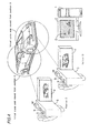
- FIG.2 is a schematic view illustrating a first embodiment according to the present invention.
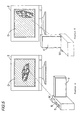
- FIG.3 is an explanatory view showing a first operational movement of the first embodiment.
- FIG.4 is an explanatory view showing a second operational movement of the first embodiment.
- FIG.5 is an explanatory view showing a third operational movement of the first embodiment.
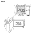
- FIG.6 is a schematic view illustrating a second embodiment.
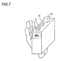
- FIG.7 is a schematic view illustrating a third embodiment.
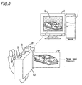
- FIG.8 is a schematic view illustrating a fourth embodiment.
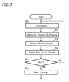
- FIG.9 is a flow chart showing an operational procedure of the fourth embodiment.
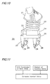
- FIG.10 is an explanatory view showing a roller skate employed in a fifth embodiment.
- FIG. 11 is an explanatory diagram explaining a movement in a virtual 3-demensional space.
- FIG.12 is an explanatory view showing a roller skate employed in a sixth embodiment.
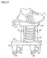
- FIG.13 is an explanatory view showing a roller skate employed in a seventh embodiment
- FIG.14 is an explanatory view showing a roller skate employed in a eighth embodiment
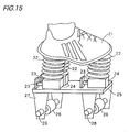
- FIG.15 is an explanatory view showing a roller skate employed in a ninth embodiment
- FIG.1 is the block diagram illustrating an outline of the constitution of a system to display and to output images displayed on a computer screen processed by the selecting means according to the present invention.
- numeric character 1 is a computer equipped with a display device 2 and a numeric character 3 is a selecting means.
- a numeric character 4 is a detecting means to detect a relative position and a status (gradient) of the selecting means 3 against a reference position.
- a numeric character 5 is an area selecting means to select a certain area on the above-mentioned computer screen according to changed values acquired from detected values by the detecting means 4 after moving the selecting means 3.
- An alphabetic character "d” is a display means to display the selected area.
- Sign 1v represents a memory arranged in the computer 1, which can store image data for selection.
- the selecting means 3 is equipped with the detecting means 4 to detect its posture and position and the display means d to display the selected area out of the image displayed on the screen D connected to the computer 1.
- the selecting means 3 has a virtual reference point O and a virtual focus f fixed to itself.
- a virtual half line L starting from the virtual reference point O and a space field angle ⁇ which determines a viewing angle to the virtual space E corresponding a displaying width of the display means d, are fixed to the selecting means 3.
- the selecting means 3 memorizes the virtual reference point O as a central point o of the 3-dimensional space E and the half line L as a half line T based on the detected posture and position of itself, when the selecting means 3 is started or initialized. Values o and T are replaced new ones whenever the selecting means 3 is started or initialized and the posture against the virtual half line L is set 0 degree.
- the detecting means 4 to detect the posture and the position of the selecting means 3 is arranged to measure; a distance X between the reference point O and the point o; an angle Y formed by the virtual reference half line L and the half line T; and a self rotating angle Z around the virtual half line L.
- the selecting means 3 regularly transmits values X, Y and Z to the computer 1.
- the screen D connected computer 1 is designed to display the image focused on a plane where the virtual reference point O is included, perpendicular to the axis of the lens with the virtual focus f, as if the lens is placed on the virtual reference point O toward the 3-dimensional area E.
- the display means d is arranged to display an area analogous shape to the image on the screen D, but rotated by the degree Z.
- the virtual reference point is defined as O1.
- the virtual reference half line is defined as L1.
- the distance between O 1 and o, the angle formed by L1 and the virtual half line T, and the self rotating angle around L1 are defined as X1, Y1 and Z1 respectively.
- the virtual reference point is defined as O2.
- the virtual reference half line is defined as L2.
- the distance between O2 and o, the angle formed by L2 and the virtual half line T, and the self rotating angle around L1 are defined as X2, Y2 and Z2 respectively.
- the variables at the end of the moving operation are stored in the memory 1v of the computer 1.
- the image displayed on display means d is fixed and not influenced by fluctuations in posture or position of the selecting means 3.
- the selecting means 3 re-sets the center point o of the virtual 3-dimensional space E and the half line T so as to conform to respective variables O2, X2, Y2 and Z2.
- the display means d is arranged to display only selected area or its alternative area displayed in the screen D.
- the shape of the selected or alternative area in the screen D corresponds to the analogous image in the display means d, but rotated by the self rotating angle Z.
- a magnifying rate of the image on the screen D connected to the computer is set in proportion to a value, X1+ ⁇ divide by ⁇ .
- ⁇ is a predetermined value against the image at starting or initializing operation of the selecting means 3.
- a plane where the point o is included and normal to the half line T is defined as a plane P.
- a point where the plane P and the virtual reference half line L1 cross is defined as a point o1.
- the center of the image displayed on the screen D corresponds to the point o1, when the center point of the image in the screen D at starting or initialization of the selecting means 3 is set on the point o.
- FIG.2 shows a schematic view of the first embodiment according to the present invention where the virtual space area having a predetermined relation between the screen D of the computer 1 and the display means d of the selecting means 3.
- a car is displayed.
- An optical gyro-sensor and three velocity sensors arranged perpendicularly to each other are equipped in the main body of the selecting means 3 so as to measure changed values in posture and position of the selecting means 3. Measured values are regularly transmitted to the computer 1 via a wireless transmission (not shown).
- the display means d a liquid crystal display (Hereinafter referred as "LCD".) is attached to the main body of the selecting means 3.
- the LCD d is movably fitted to the main body of the selecting means 3 via a hinge.
- the LCD d can be folded up to a position parallel to the main body of the selecting means 3.
- the LCD can be fitted at any angle between 0 where the LCD is parallel to the plane of FIG.2 and 90 degrees where the LCD is perpendicular to the plane.
- the LCD attached to the selecting means 3 is a display screen for a second computer equipped in the selecting means 3.
- the second computer measures the position and the posture of the selecting means 3 by the aid of the gyro-sensor and velocity sensors after receiving the virtual 3-dimensional space data of the computer 1.
- the measured results are transmitted to the computer 1 and are used for simulating images seen through the virtual lens with focus f aligned with the light axis of the selecting means 3 shown in FIG.2 by the aid of a software. Simulated images are displayed on the display means d of the selecting means 3.
- a button M When a button M is pushed within one second it functions as a changeover switch for the screen D connected to the computer 1 from a still screen to a motion screen in accordance with the movement of the selecting means 3 or vice versa.
- the posture and position of the selecting means 3 is memorized after initializing the selecting means 3.
- 2-dimensional still image with 600 pixels down and 800 pixels across out of 3000 pixels by 4000 pixels is displayed on the screen D of the computer 1.
- An image with 300 pixels by 400 pixels having the same center point as the 2-dimensional still image is displayed on the LCD display means d as image data area for editing by the computer afterward.
- the selecting means 3 is initialized by pressing the button M more than one second by facing the selecting means toward the center of the screen D so that the posture and position are memorized.
- FIG.3 shows a moving mode switched by the button M in FIG.2.
- a broken line in FIG.2 is a virtual vector that goes through the center of the gravity of the selecting means 3 and its relative position to the virtual vector is always fixed.
- the button is pushed again, it is changed to the still mode where the displayed image is fixed as the selected image.
- FIG.4 is the schematic view for explaining the selecting means 3 that is moved from a position C to D parallel to a light axis.
- the LCD d of the selecting means 3 displays only rear part of the car, while at the position D the LCD d displays the front of the car so that the movement of the image in the virtual space is understood intuitively.
- the screen D of the computer 1 and LCD d display the same results, but the LCD d displays partial image while the screen D displays the whole image.
- the image area for printing displayed on the screen D also rotates by the degree ⁇ where selective image data area having the same center point as the 2-dimensional image on the screen D when ⁇ is 90 degrees, corresponds to data area with 300 pixels by 400 pixels.
- the relation between displayed image selected by the selecting means 3 and the selecting means 3 is arranged in the quite similar way to a relation between a printed photograph and a 35mm film camera, which enables the selecting means to operate intuitively as the 35mm film camera.
- the present mode is kept until the posture and position return to operative area.
- FIG.6 is a schematic illustration of the second embodiment according to the present invention.
- a combination of a laser light source, a photo-detector for the laser light, two galvano-mirrors to reflect the laser light so as to scan the area 2-dimensionally and two angle detectors for each galvano-mirror are employed in place of the combination of the photo-gyro-sensor and velocity sensors as in the embodiment 1.
- two corner cube prisms 11, 12 are fixed so as to reflect the laser light from the selecting means 3 and to return the laser light to the photo-detector of the selecting means 3.
- directions of the two corner cube prisms are measured.
- a position of the screen D against the virtual 3-dimensional space is calculated based on the measured directions and the distance between two corner cube prisms 11 and 12.
- FIG.7 is a schematic view of the third embodiment of the selecting means 3 according to the present invention. Since the constitution of this embodiment is same as the preceding embodiments except a finder for monitoring the image attached to the selecting means 3 instead of the display means d, further explanation is omitted.
- FIG.8 is a schematic view of the fourth embodiment of the present invention.
- a printer 10 equipped with the same functions as of the selecting means 3 in the preceding embodiments is employed in place of the selecting means 3. Since procedures are quite similar to the preceding embodiments except printing selected images in color or monochrome, further detailed explanation is omitted.
- the display means d is replaced by a paper p. Due to functions of the present invention, a printing direction, crosswise or downward, can be monitored on the display screen beforehand without any difficulties. Thus the selecting images before printing is executed more easily than before.
- FIG.9 is the flow chart depicting a basic operation of the fourth embodiment. Controlling procedures depicted in the flow chart are executed by a program stored in a CPU (not shown) equipped in a controller of the printer 10.
- the printer 10 Before printing, the printer 10 is initialized (S1) and the position and the posture of the printer 10 is stored in a memory (not shown) (S2). A processed image namely enlarged or reduced-sized image is displayed (S3) on the screen D of the display device 2. The area for printing is selected out of the displayed image by moving the printer 10 (S4). When a printing operation is selected (S5) the recording procedure starts (S6).
- FIG.10 is a schematic view illustrating the fifth embodiment according to the present invention where a roller skate is used as a moving means and a detecting means to detect a moved distance in the virtual space.
- FIG. 11 is a block diagram to explain movements of a person in the virtual 3-dimensional space, who has the selecting means shown in FIG.2 and wears the roller skate shown in FIG. 10.
- Sports shoe 21 is supported by expandable bellows 22, to which air pump 23 is connected via a connecting member 24 so as to control quantity of air in the bellows 22.
- the connecting member 24 is supported by a supporting board 25, to which two rollers 26 are fixed via roller supporting members 27.
- An encoder 28 is attached to the front roller and a motor 29 is attached to the rear roller.
- the connecting member 24 the following devices are accommodated; a load gauge, a controlling circuit for controlling the encoder 28 /the motor 29, a controlling circuit for controlling the air pump 23 and a wire-less communication means for mutual transmission/receipt of encoded values in the encoder and of pressure values in the bellows between the two roller skate shoes.
- respective postures of a roller skater are defined as follows.
- B' A posture immediately after walking where the right shoe is raised from the ground.
- D' A posture after the right shoe touches ground where a weight of the skater is shifting from the left shoe to the right shoe.
- a posture is specified as A, B, C, D, A', B', C', D' or E according to a load difference between the right and left shoes and the duration of the same posture.
- Defined postures are determined according to average load values on the right and left shoes at a standing posture for 10 seconds.
- a present posture, D or D' is determined as follows.
- the average weighed values for 10 seconds on the right and left at the standing posture are 24Kg and 25Kg respectively.
- digits less than the decimal point are cut off to obtain integers.
- Values plus/minus 2 Kg are ranges for D and D' postures.
- the posture D is specified as follows; the load on the left is more than 22Kg and less than 24Kg, while the load on the right is more than 25Kg and less than 27Kg.
- the posture D' is specified as follows; the load on the left is more than 24Kg and less than 26Kg, while the load on the right is more than 23Kg and less than 25Kg.
- the posture B is specified as the load on the right exceeds 90% of the weight, i.e. more than 44Kg. While the posture B' is specified that the load on the right exceeds 90% of the weight, i.e. more than 44Kg.
- the posture C is defined as the posture after the posture B is over.
- the posture C' is defined as the posture after the posture B' is over.
- the posture A is defined as the posture after the posture D' is over.
- the posture A' is defined as the posture after the posture D is over.
- the posture When each posture keeps its status for 0.2 second within 5% margin of its load fluctuation, the posture is defined as E.
- the rollers 26 rotate to meet a rotating velocity obtained from a predetermined stride and walking velocity.
- the stride is set 60Cm and the initial velocity is set 2.4Km/Hr. beforehand.
- the air in the bellows 22 is discharged by the air pump 23 during walking on a flat plane so as to keep a distance between the grounding surface of the roller 26 and the sole of the shoe 21 constant.
- the roller motor 28 of the more loaded roller skate is controlled by a rotating number of the encoder 27 so that the more loaded roller skate moves backward by a distance corresponding to the stride.
- the right and left roller motors rotate so as to compensate the unfilled moving distance during postures C, D and A'. Rotating velocity of the following posture B' is determined by the stride and duration of the posture B.
- the right and left roller motors rotate so as to compensate the unfilled moving distance during postures C', D' and A.
- Rotating velocity of the following posture B is determined by the stride and duration of the posture B'.
- a walking movement whether on the flat plane, on the ascending slope or on the descending slope is selected by a changeover switch (not shown in figures).
- the sports shoes 21 can be replaced by sandals, leather shoes etc. as far 'as they are able to fit to the roller skates.
- Sports shoes having compartments under the soles to accommodate sand and pebbles are one of the modifications to feel real walking on the ground.
- Variable gradients on the ascending or descending slope are attained by adjusting extending lengths of bellows 22 according to measured extending lengths and by controlling rotating numbers by the motors 29 according to the rotating numbers of the encoders 28.
- the gradient against the reference position of the selecting means 3 is detected.
- the relative position against the reference position in the 3-dimensional virtual space is detected by the roller skates 20, which realizes the function of the detecting means 4 in FIG.1.
- the constitution shown in FIG. 11 realizes the function of the detecting means 4 shown in FIG. 1 by adding the detected position value of the selecting means 3 against the reference position to the relative position value of the roller skates 20 against the reference position in the 3-dimensional virtual space.
- FIG.12 is an explanatory view to showing a roller skate as moving means and detecting means to detect the movement in the virtual space in the embodiment 6.
- a different feature from the embodiment 5 is that the sports shoe 21 is supported by the connecting member 24, and the connecting member 24 is supported by the expandable bellows 22.
- FIG.13 is an explanatory view showing a roller skate as moving means and detecting means to detect the movement in the virtual space in the embodiment 7.
- a different feature from the embodiment 5 is that supporting rods 30 are arranged so as to support load on declining side of the bellows 22 by adjusting lengths of the supporting rods.
- FIG.14 is an explanatory view showing a roller skate as moving means and detecting means to detect the movement in the virtual space in the embodiment 8.
- a rotating board 31 is arranged between the supporting board 25 and the roller 26 equipped with the encoder 28, and two rollers 26 equipped with motors 29 are arranged in stead of one roller. By introducing the rotating board 31 the roller 26 equipped with the encoder 28 can change moving in different directions easily. By selecting different rotating numbers of rollers 26 equipped with motors 29, rolling directions can be changed flexibly.
- FIG.15 is an explanatory view showing a roller skate as moving means and detecting means to detect the movement in the virtual space in the embodiment 9.
- a different feature from the embodiment 5 is as follows; Three sets of the bellows 22 for supporting the sports shoe 21 and the air pumps 23 are equipped so as to support the sports shoe 21 more adjustably according to the gradients of the sports shoe 21. Which realizes more real feeling during waking movements.
- the present invention attains easy operations such as moving, rotating, magnifying, reducing images in the virtual space, even the novice operators can deal images on the screen of the computer intuitively while observing data in the virtual space moving in the real space.
- the present invention attains easy operations such as moving, rotating, magnifying, reducing images in the virtual space, even novice operators can deal images on the screen of the computer intuitively while observing data in the virtual space feeling moving as if in the virtual space.
Landscapes
- Engineering & Computer Science (AREA)
- Multimedia (AREA)
- Signal Processing (AREA)
- General Engineering & Computer Science (AREA)
- Theoretical Computer Science (AREA)
- Physics & Mathematics (AREA)
- Computing Systems (AREA)
- Geometry (AREA)
- Computer Graphics (AREA)
- General Physics & Mathematics (AREA)
- Processing Or Creating Images (AREA)
- Facsimiles In General (AREA)
- User Interface Of Digital Computer (AREA)
- Position Input By Displaying (AREA)
- Testing, Inspecting, Measuring Of Stereoscopic Televisions And Televisions (AREA)
Abstract
Description
A': A posture immediately before walking where the right shoe is positioned rear, B': A posture immediately after walking where the right shoe is raised from the ground. C': An instant the right shoe touches the ground at the front position of the left shoe, D': A posture after the right shoe touches ground where a weight of the skater is shifting from the left shoe to the right shoe. When a certain posture among the postures A to D' explained above is kept for a predetermined duration, that posture is defined as E.
Claims (29)
- A data processing system comprising;a data accumulating means to accumulate virtual space data as a set of 3-dimensional data specifying shape,a coordinate system setting means to set a virtual reference point and virtual coordinate axes in said virtual space,a detecting means to detect a relative position and a gradient in a real space,a position specifying means to specify virtual positions in said virtual space in accordance with said position data detected by said detecting means,an area selecting means to select a desired area in said virtual space in accordance with said virtual positions specified by said position specifying means, anda storing means to store an image of said desired area selected by said selecting means.
- The data processing system according to claim 1 wherein said detecting means has a gyro-sensor.
- The data processing system according to claim 1 wherein said detecting means has an optical gyro-sensor and velocity sensors.
- The data processing system according to claim 1 wherein said detecting means has;a laser light source,galvano-mirrors to distribute the laser light,prisms to reflect the distributed laser light,a photo-detector to receive the reflected light by the prisms, andangle detectors to detect the respective moved angles of the galvano-mirrors.
- The data processing system according to claim 1 wherein said 3-dimensional data further includes data on color, dimension and texture.
- A printer comprising;a data accumulating means to accumulate virtual space data as a set of 3-dimensional data specifying shape,a coordinate system setting means to set a virtual reference point and virtual coordinate axes in said virtual space,a detecting means to detect a relative position and a gradient in a real space, anda printing means to print a desired area in said virtual space specified by said position data detected by said detecting means specified by said virtual reference point and coordinate axes.
- The printer according to claim 6 wherein said detecting means has a gyro-sensor.
- The printer according to claim 6 wherein said detecting means has an optical gyro-sensor and velocity sensors.
- The printer according to claim 6 wherein said detecting means has;a laser light source,galvano-mirrors to distribute the laser light,prisms to reflect the distributed laser light,a photo-detector to receive the reflected light by the prisms, andangle detectors to detect the respective moved angles of the galvano-mirrors.
- The printer according to claim 6 wherein said 3-dimensional data further includes data on color, dimension and texture.
- An image recording system comprising;a data accumulating means to accumulate virtual space data as a set of 3 dimensional data specifying shape,a coordinate system setting means to set a virtual reference point and virtual coordinate axes in said virtual space,a detecting means to detect a relative position and a gradient in a real space,a position specifying means to specify virtual positions in said virtual space in accordance with said position data detected by said detecting means,an area selecting means to select a desired area in said virtual space in accordance with said virtual positions specified by said position specifying means, anda printing means to print said selected desired area in said virtual space.
- The image recording system according to claim 11 wherein a gyro-censor is used in said detecting means.
- The image recording system according to claim 11 wherein an optical gyro-sensor and velocity sensors are used in said detecting means.
- The image recording system according to claim 11 wherein;a laser light source,galvano-mirrors to distribute the laser light, prisms to reflect the distributed laser light,a photo-detector to receive the reflected light by the prisms, andangle detectors to detect the respective moved angles of the galvano-mirrors are used in said detecting means.
- The image recording system according to claimll wherein said 3-dimensional data further includes data on color, dimension and texture.
- An image recording method comprising steps of;accumulating virtual space data as a set of 3-dimensional data specifying shape,setting a coordinate system by setting a virtual reference point and virtual coordinate axes in said virtual space,detecting a relative position and a gradient in a real space,specifying virtual positions in said virtual space in accordance with said position data detected by said detecting step,selecting a desired area in said virtual space in accordance with said virtual positions specified by said position specifying step, andprinting said selected desired area in said virtual space.
- The image recording method according to claim 16 wherein a gyro-sensor is used at said detecting step.
- The image recording method according to claim 16 wherein an optical gyro-sensor and velocity sensors are used at said detecting step.
- The image recording method according to claim 16 wherein;a laser light source,galvano-mirrors to distribute the laser light, prisms to reflect the distributed laser light,a photo-detector to receive the reflected light by the prisms andangle detectors to detect the respective moved angles of the galvano-mirrors are used at said detecting step.
- The image recording method according to claim 16 wherein said 3-dimensional data further includes data on color, dimension and texture.
- A data processing system comprising;a data accumulating means to accumulate virtual space data as a set of 3-dimensional data specifying shape,a coordinate system setting means to set a virtual reference point and virtual coordinate axes in said virtual space,a virtual position detecting means to detect a relative position and a gradient against said virtual reference point,a moving means to move in said virtual space,an area selecting means to select a desired area in said virtual space in accordance with changed values caused by said moving action of said moving means detected by said detecting means, anda storing means to store an image of said desired area selected by said selecting means..
- The data processing system according to claim 21 wherein said moving means has;rollers,a counting member to count rotated amount of said rollers,a controlling member to control rotating velocity of said rollers,supporting members formed monolithically with said rollers to support a heavy load,a measuring member to measure said load to the supporting members, anda space adjuster to adjust a space between said rollers and said supporting members in accordance with said measured load value by said measuring member.
- The data processing system according to claim 21 or claim 22 wherein said virtual space moving means has a measuring member to measure said space between said rollers and said supporting members.
- The data processing system according to one of the claims 21 to 23 wherein said moving means also functions as a detecting means to detect a position in said virtual space.
- The data processing system according to one of the claims 21 to 24 wherein said data processing system has a plurality of moving means in said virtual space.
- The data processing system according to claim 21 wherein said 3-dimensional data further includes data on color, dimension and texture.
- A selecting device for manipulating a set of 3-dimensional data comprising means for measuring the coordinates of the device relative to a display displaying 3-dimensional data, and means for transmitting coordinate information to a processor so as to cause the processor to manipulate and display the stored data.
- A device according to claim 27, including means for selecting an area of the displayed data.
- A device according to claim 27 or claim 28 wherein the device has an associated display screen.
Applications Claiming Priority (4)
| Application Number | Priority Date | Filing Date | Title |
|---|---|---|---|
| JP2000005754 | 2000-01-06 | ||
| JP2000005754 | 2000-01-06 | ||
| JP2000401556A JP2001256511A (en) | 2000-01-06 | 2000-12-28 | Data processing system, printer, image recording system, and image recording method |
| JP2000401556 | 2000-12-28 |
Publications (3)
| Publication Number | Publication Date |
|---|---|
| EP1115091A2 true EP1115091A2 (en) | 2001-07-11 |
| EP1115091A3 EP1115091A3 (en) | 2004-04-14 |
| EP1115091B1 EP1115091B1 (en) | 2006-05-03 |
Family
ID=26583504
Family Applications (1)
| Application Number | Title | Priority Date | Filing Date |
|---|---|---|---|
| EP01300066A Expired - Lifetime EP1115091B1 (en) | 2000-01-06 | 2001-01-05 | Data processing system, printer, image recording system and image recording method |
Country Status (4)
| Country | Link |
|---|---|
| US (1) | US7031017B2 (en) |
| EP (1) | EP1115091B1 (en) |
| JP (1) | JP2001256511A (en) |
| DE (1) | DE60119180T2 (en) |
Cited By (1)
| Publication number | Priority date | Publication date | Assignee | Title |
|---|---|---|---|---|
| DE102007039669A1 (en) * | 2007-08-22 | 2009-02-26 | Navigon Ag | Display device with image surface |
Families Citing this family (4)
| Publication number | Priority date | Publication date | Assignee | Title |
|---|---|---|---|---|
| JP2004199496A (en) * | 2002-12-19 | 2004-07-15 | Sony Corp | Information processing apparatus and method, and program |
| US20050068549A1 (en) * | 2003-09-26 | 2005-03-31 | Denny Jaeger | Graphic user interface and method for selectively printing objects displayed on a display device |
| DE102007052650B4 (en) * | 2007-11-05 | 2016-11-03 | Siemens Healthcare Gmbh | An imaging system and method for operating an imaging system |
| EP3580637A1 (en) | 2017-02-08 | 2019-12-18 | Cybershoes Gmbh | Apparatus for capturing movements of a person using the apparatus for the purposes of transforming the movements into a virtual space |
Family Cites Families (5)
| Publication number | Priority date | Publication date | Assignee | Title |
|---|---|---|---|---|
| IL92220A (en) | 1989-11-06 | 1993-02-21 | Ibm Israel | Three-dimensional computer input device |
| AUPN298995A0 (en) | 1995-05-16 | 1995-06-08 | Phillips, Scott | Vr walker |
| FI102644B (en) | 1995-09-12 | 1999-01-15 | Varian Dosetek Oy | Device and method for digitizing coordinates and / or images |
| JPH1049290A (en) | 1996-08-05 | 1998-02-20 | Sony Corp | Information processing apparatus and method |
| JP4035867B2 (en) * | 1997-09-11 | 2008-01-23 | 株式会社セガ | Image processing apparatus, image processing method, and medium |
-
2000
- 2000-12-28 JP JP2000401556A patent/JP2001256511A/en not_active Withdrawn
-
2001
- 2001-01-03 US US09/752,553 patent/US7031017B2/en not_active Expired - Fee Related
- 2001-01-05 DE DE60119180T patent/DE60119180T2/en not_active Expired - Lifetime
- 2001-01-05 EP EP01300066A patent/EP1115091B1/en not_active Expired - Lifetime
Cited By (1)
| Publication number | Priority date | Publication date | Assignee | Title |
|---|---|---|---|---|
| DE102007039669A1 (en) * | 2007-08-22 | 2009-02-26 | Navigon Ag | Display device with image surface |
Also Published As
| Publication number | Publication date |
|---|---|
| JP2001256511A (en) | 2001-09-21 |
| DE60119180T2 (en) | 2007-02-08 |
| US20010021028A1 (en) | 2001-09-13 |
| DE60119180D1 (en) | 2006-06-08 |
| EP1115091A3 (en) | 2004-04-14 |
| EP1115091B1 (en) | 2006-05-03 |
| US7031017B2 (en) | 2006-04-18 |
Similar Documents
| Publication | Publication Date | Title |
|---|---|---|
| US7576742B2 (en) | Picture display controller, moving-picture information transmission/reception system, picture display controlling method, moving-picture information transmitting/receiving method, and computer program | |
| US8842166B2 (en) | Storage medium having stored therein stereoscopic image display program, stereoscopic image display device, stereoscopic image display system, and stereoscopic image display method | |
| JP3728160B2 (en) | Depth image measuring apparatus and method, and mixed reality presentation system | |
| EP2457627B1 (en) | Portable type game device and method for controlling portable type game device | |
| JP3847753B2 (en) | Image processing apparatus, image processing method, recording medium, computer program, semiconductor device | |
| US8633871B2 (en) | Image processing apparatus and image processing method | |
| CN1923326B (en) | Information processing system | |
| US8814678B2 (en) | Apparatus and method for gyro-controlled gaming viewpoint with auto-centering | |
| EP1764141A1 (en) | Video game program and video game system | |
| US8952956B2 (en) | Computer-readable storage medium having stored therein display control program, display control apparatus, display control system, and display control method | |
| EP2565848B1 (en) | Program, information processing apparatus, information processing system, and information processing method | |
| JP2002058045A (en) | System and method for causing a real object to appear in a virtual three-dimensional space | |
| JP4758560B2 (en) | Immersive display system | |
| US7031017B2 (en) | Data processing system, printer, image recording system and image recording method | |
| US20120133641A1 (en) | Hand-held electronic device | |
| CN108513652A (en) | The control method and device of holder | |
| JP7341674B2 (en) | Information processing device, information processing method and program | |
| JP4991541B2 (en) | Method and system for controlling a display | |
| JP3558144B2 (en) | Eye point measuring device when wearing eyeglass frames | |
| KR20150010070A (en) | Method and apparatus for dispalying images on portable terminal | |
| KR101960046B1 (en) | Method for producing virtual reality image, portable device in which VR photographing program for performing the same is installed, and server supplying the VR photographing program to the portable device | |
| JP2022062696A (en) | Program and field of view control method | |
| TWI587176B (en) | Action virtual reality operation method, system and storage medium thereof | |
| JP2006294066A (en) | Image processor, image processing method, recording medium, computer program, and semiconductor device | |
| CN121623299A (en) | Control device, control method, storage medium, and program product |
Legal Events
| Date | Code | Title | Description |
|---|---|---|---|
| PUAI | Public reference made under article 153(3) epc to a published international application that has entered the european phase |
Free format text: ORIGINAL CODE: 0009012 |
|
| AK | Designated contracting states |
Kind code of ref document: A2 Designated state(s): AT BE CH CY DE DK ES FI FR GB GR IE IT LI LU MC NL PT SE TR |
|
| AX | Request for extension of the european patent |
Free format text: AL;LT;LV;MK;RO;SI |
|
| RIC1 | Information provided on ipc code assigned before grant |
Ipc: 7G 06F 3/033 B Ipc: 7G 06T 17/40 A |
|
| PUAL | Search report despatched |
Free format text: ORIGINAL CODE: 0009013 |
|
| RIC1 | Information provided on ipc code assigned before grant |
Ipc: 7G 06T 17/40 A Ipc: 7G 06F 3/033 B Ipc: 7G 06F 3/00 B |
|
| AK | Designated contracting states |
Kind code of ref document: A3 Designated state(s): AT BE CH CY DE DK ES FI FR GB GR IE IT LI LU MC NL PT SE TR |
|
| AX | Request for extension of the european patent |
Extension state: AL LT LV MK RO SI |
|
| 17P | Request for examination filed |
Effective date: 20040826 |
|
| AKX | Designation fees paid |
Designated state(s): DE FR GB IT |
|
| 17Q | First examination report despatched |
Effective date: 20050415 |
|
| GRAP | Despatch of communication of intention to grant a patent |
Free format text: ORIGINAL CODE: EPIDOSNIGR1 |
|
| GRAS | Grant fee paid |
Free format text: ORIGINAL CODE: EPIDOSNIGR3 |
|
| GRAA | (expected) grant |
Free format text: ORIGINAL CODE: 0009210 |
|
| AK | Designated contracting states |
Kind code of ref document: B1 Designated state(s): DE FR GB IT |
|
| PG25 | Lapsed in a contracting state [announced via postgrant information from national office to epo] |
Ref country code: IT Free format text: LAPSE BECAUSE OF FAILURE TO SUBMIT A TRANSLATION OF THE DESCRIPTION OR TO PAY THE FEE WITHIN THE PRESCRIBED TIME-LIMIT;WARNING: LAPSES OF ITALIAN PATENTS WITH EFFECTIVE DATE BEFORE 2007 MAY HAVE OCCURRED AT ANY TIME BEFORE 2007. THE CORRECT EFFECTIVE DATE MAY BE DIFFERENT FROM THE ONE RECORDED. Effective date: 20060503 |
|
| REG | Reference to a national code |
Ref country code: GB Ref legal event code: FG4D |
|
| REF | Corresponds to: |
Ref document number: 60119180 Country of ref document: DE Date of ref document: 20060608 Kind code of ref document: P |
|
| PLBE | No opposition filed within time limit |
Free format text: ORIGINAL CODE: 0009261 |
|
| STAA | Information on the status of an ep patent application or granted ep patent |
Free format text: STATUS: NO OPPOSITION FILED WITHIN TIME LIMIT |
|
| 26N | No opposition filed |
Effective date: 20070206 |
|
| EN | Fr: translation not filed | ||
| PG25 | Lapsed in a contracting state [announced via postgrant information from national office to epo] |
Ref country code: FR Free format text: LAPSE BECAUSE OF FAILURE TO SUBMIT A TRANSLATION OF THE DESCRIPTION OR TO PAY THE FEE WITHIN THE PRESCRIBED TIME-LIMIT Effective date: 20070309 |
|
| PG25 | Lapsed in a contracting state [announced via postgrant information from national office to epo] |
Ref country code: FR Free format text: LAPSE BECAUSE OF FAILURE TO SUBMIT A TRANSLATION OF THE DESCRIPTION OR TO PAY THE FEE WITHIN THE PRESCRIBED TIME-LIMIT Effective date: 20060503 |
|
| PGFP | Annual fee paid to national office [announced via postgrant information from national office to epo] |
Ref country code: DE Payment date: 20170131 Year of fee payment: 17 |
|
| PGFP | Annual fee paid to national office [announced via postgrant information from national office to epo] |
Ref country code: GB Payment date: 20170130 Year of fee payment: 17 |
|
| REG | Reference to a national code |
Ref country code: DE Ref legal event code: R119 Ref document number: 60119180 Country of ref document: DE |
|
| GBPC | Gb: european patent ceased through non-payment of renewal fee |
Effective date: 20180105 |
|
| PG25 | Lapsed in a contracting state [announced via postgrant information from national office to epo] |
Ref country code: DE Free format text: LAPSE BECAUSE OF NON-PAYMENT OF DUE FEES Effective date: 20180801 |
|
| PG25 | Lapsed in a contracting state [announced via postgrant information from national office to epo] |
Ref country code: GB Free format text: LAPSE BECAUSE OF NON-PAYMENT OF DUE FEES Effective date: 20180105 |