EP1115056A2 - Method and circuits for performing a quick search of the minimum/maximum value among a set of numbers - Google Patents
Method and circuits for performing a quick search of the minimum/maximum value among a set of numbers Download PDFInfo
- Publication number
- EP1115056A2 EP1115056A2 EP00480106A EP00480106A EP1115056A2 EP 1115056 A2 EP1115056 A2 EP 1115056A2 EP 00480106 A EP00480106 A EP 00480106A EP 00480106 A EP00480106 A EP 00480106A EP 1115056 A2 EP1115056 A2 EP 1115056A2
- Authority
- EP
- European Patent Office
- Prior art keywords
- sub
- value
- minimum
- bit
- maximum
- Prior art date
- Legal status (The legal status is an assumption and is not a legal conclusion. Google has not performed a legal analysis and makes no representation as to the accuracy of the status listed.)
- Granted
Links
Images




Classifications
-
- G—PHYSICS
- G06—COMPUTING OR CALCULATING; COUNTING
- G06F—ELECTRIC DIGITAL DATA PROCESSING
- G06F9/00—Arrangements for program control, e.g. control units
- G06F9/06—Arrangements for program control, e.g. control units using stored programs, i.e. using an internal store of processing equipment to receive or retain programs
- G06F9/30—Arrangements for executing machine instructions, e.g. instruction decode
- G06F9/30003—Arrangements for executing specific machine instructions
- G06F9/30007—Arrangements for executing specific machine instructions to perform operations on data operands
- G06F9/30021—Compare instructions, e.g. Greater-Than, Equal-To, MINMAX
-
- G—PHYSICS
- G06—COMPUTING OR CALCULATING; COUNTING
- G06F—ELECTRIC DIGITAL DATA PROCESSING
- G06F7/00—Methods or arrangements for processing data by operating upon the order or content of the data handled
- G06F7/22—Arrangements for sorting or merging computer data on continuous record carriers, e.g. tape, drum, disc
Definitions
- the present invention relates to techniques to search a number having a determined value in a set of numbers and more particularly to a method and circuits for searching the number having the minimum/maximum value in this set of numbers.
- the described solution allows a very fast search, improving thereby the response time and also providing a constant time response whatever the quantity of numbers among said set in which the minimum/maximum search is conducted.
- the most known method to determine the number having the minimum value among a set of numbers consists in comparing a number with another number of the set, selecting the number having the lowest value and then proceeding the same way with the selected number until all the numbers of the set have been processed, to identify the number(s) having the minimum value.
- this solution which requires a lot of processing steps that are sequentially performed is not optimized and presents major drawbacks.
- the response time is prohibitive.
- This solution, and more generally all solutions that are derived therefrom have response time that are not acceptable for most applications to date mainly because they are based on sequential processing algorithms.
- the response time is degraded because it is function of the precision (the number q of bits used to code said numbers) and also depends upon the quantity of numbers in which the minimum/maximum value is searched.
- Another approach consists in a simultaneous evaluation (i.e. in a parallel way) of all the bits of a same weight for the totality of the numbers in which the minimum/maximum value is searched.
- Such a parallel approach has been recently described in the technical literature in connection with an advanced family of neural silicon chips that are manufactured and commercialized by IBM France under the ZISC036 label (ZISC is a registered Trade Mark of IBM Corp).
- ZISC is a registered Trade Mark of IBM Corp.
- circuit 10 which is comprised of p blocks 11 referenced 11-1 to 11-p (one per Number to be searched) processes a one bit slice, in this case the second bit (bit 2 or Bit2) of said Numbers. Note that all the q slices are of identical construction.
- a block 11 is quite similar to the circuit shown in FIG. 28B of the above cited US patent.
- block 11-1 comprises a two-way OR gate 12-1, a two-way AND gate 13-1 and a two-way OR gate 14-1.
- the two latter gates form sub-block 15-1 that has the key role of selecting/deselecting the Number associated thereto, Number 1 in this case.
- signals Exout 1-2 and Bit 1-2 are applied to OR gate 12-1.
- Signals Exout 1-2 and Bit 1-2 represent the state of Number 1 (i.e. selected or deselected) and the value of bit 2 for that Number 1 respectively.
- the same construction applies to all blocks 11-1 to 11-p.
- the outputs of OR gates 12-1 to 12-p are applied to a p-way AND gate 16 (AND gate 16 needs as many inputs as there are Numbers to be simultaneously processed) to produce a signal which is inverted in inverter 17.
- AND gate 16 and inverter 17 form block 18.
- the resulting signal is applied to a first input of all AND gates 13-1 to 13-p whose other input receives the corresponding Bit signal i.e. Bit 1-2 to Bit p-2 .
- the outputs of AND gates 13-1 to 13-p and the corresponding Exout signals, i.e. Exout 1-2 to Exout p-2 are applied to OR gates 14-1 to 14-p respectively.
- the signals that are output by OR gates 14-1 to 14-p are labeled Exout 1-3 to Exout p-3 to still remain consistent with that terminology.
- Block 18 which is common for all the p blocks 11-1 to 11-p allows to determine the minimum value for bit 2 of the p numbers, i.e. for one bit only.
- each slice of one bit of all Numbers 1 to p is processed in sequence, one slice per step (e.g. per clock cycle) from the most significant bit (MSB) to the less significant bit (LSB).
- the response time of this method is then function of the quantity q of slices, i.e. the number of bits used to code Number 1 to Number p.
- this solution is parallel for what concerns the p Numbers and sequential for what concerns the q bits of coding. So that, whatever the value of p , the computational time depends only of the number of bits/slices q .
- the Exout signal representing the exclusion bit, is used to select/deselect the corresponding Number during the evaluation process.
- a Number is selected as long as the Exout signal is equal to a logic "0" and it is deselected as soon as it is equal to a logic "1".
- a Number e.g. Number 1
- Exout 1-(i+1) is equal to " 1 "
- all the next signals: Exout 1-(i+2), ... , , Exout 1-q will be set to " 1 ".
- Number 1 will not be taken into account anymore whatever its value and the values of signals Bit 1-(i+1) , ... , Bit 1-q are inhibited.
- this solution requires as many steps as the quantity q of bits used to code Numbers 1 to p limiting thereby the search process speed and is clearly silicon room consuming.
- the method for performing the search of the minimum/maximum value among a set of p numbers referred to as Numbers coded in a binary format on q bits comprises the steps of :
- the circuit for searching the minimum/maximum value among a set of p numbers referred to as Numbers coded in a binary format on q bits comprises:
- the method of the present invention thus significantly improves the response time of the minimum/maximum value search by parallelizing most of the computations if not all, so that it is no longer dependent of the quantity q of bits to code the numbers to be searched so that the number of steps of the minimum/maximum evaluation process can be significantly inferior.
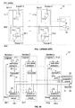
- FIG. 1 schematically shows the circuit used to perform the minimum/maximum value search on a bit slice of a set of p numbers such as described in US patent 5,740,326 mentioned above.
- FIG. 2A shows the base architecture of the searching circuit that is used to perform the minimum/maximum value search among p numbers labeled Number 1 to Number p coded on q bits wherein the q bits are processed in a partially parallel operation according to a first preferred embodiment of the present invention.
- FIG. 2B shows another architecture of the searching circuit of FIG. 2A wherein the q bits are processed in a totally parallel operation according to a second preferred embodiment of the present invention.
- FIG. 3 which is comprised of FIGS. 3(a) and 3(b) illustrate two variants of the conventional "thermometric" technique of coding.
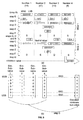
- FIG. 4 shows the essential steps of the algorithm at the base of the method of the present invention.
- FIG. 5 which is comprised of FIGS. 5(a) and 5(b) illustrates the method of the present invention in the particular step of searching the minimum value among a set of 4 numbers for the sake of illustration.
- FIGS. 6A and 6B respectively show an hardware implementation of the main circuits forming the innovative searching circuit of FIG. 2A without and with a decoder.
- FIG. 7 shows an hardware implementations of the main circuits of a slice of the innovative searching circuit of FIG. 2B with a decoder.
- the value of each Number coded on q bits is split into a plurality K of smaller values coded on n bits referred to hereinbelow as sub-values. Then, the n-bit coded sub-values are encoded on m bits using an adequate encoder, so that each sub-value can be examined in only one step to allow a search process as quick as possible.
- the use of a decoder significantly reduces the hardware that is finally required to physically implement the searching circuits of the present invention.
- circuit 19 consists of p identical blocks labeled 20-1 to 20-p. For instance, let us consider block 20-1 for sake of illustration. It first comprises a register 21-1 to store Number 1 coded in a binary format, e.g.
- register 21-1 does not necessarily belongs to block 20-1 and could be seen as an external register or a RAM as well.
- the sub-value extractor is a shift register provided with a shift control input connected to a sequencer in the control logic CL (not shown in details) to output the sub-values in sequence from slices 1 to K for all the Numbers. It is important to understand that all the sub-values of a same rank forming a slice will be processed within one step during the minimum value evaluation process. For deselected Numbers, the sub-value will be replaced by a neutral value, e.g. a series of n " 1 " for the minimum search, that will have no influence during the minimum value evaluation process.
- Block 20-1 further comprises an encoder referenced 23-1 and a selection/deselection circuit 24-1.
- the encoder 23-1 For each n-bit coded sub-value, the encoder 23-1 generates a corresponding m-bit encoded sub-value that is applied to a first input (comprised of m wires) of said selection/deselection circuit 24-1 and to a minimum evaluator circuit 25, which, in essence, is quite similar to block 18 shown in FIG. 1.
- the output of the minimum evaluator circuit 25 is applied to a second input (comprised of m wires) of the selection/deselection circuit 24-1 (a similar construction applies each block 20 of circuit 19).
- the output of the selection/deselection circuit 24-1 which transports the exclusion signal Exout 1 is either connected to the sub-value extractor circuit 22-1 or to the encoder 23-1 in order to force a set of neutral bits in case Number 1 is deselected.
- Each of the selection/deselection circuits 24-1 to 24-p includes a latch that is connected to the control logic CL so that at the initial stage of the minimum value evaluation process, all Numbers 1 to Number p are selected.
- signals Exout 1 to Exout p are set to a logic "0" to allow all Numbers to be processed.
- searching circuit 19 is adapted to function according to a first operating mode wherein the sub-values generated by the encoders 23-1 to 23-p and the minimum sub-value (as determined by the minimum evaluator circuit 25) in the encoded format (i.e. on m bits) are compared in parallel in each of the selection/deselection circuits 24-1 to 24-p.
- searching circuit 19 is essentially parallel in the sense that the p numbers are processed simultaneously, but partially remains sequential in that the numbers are processed slice by slice of n-bit coded sub-values.
- the minimum value can be found in the register of the still selected Numbers, i.e. those which have an Exout signal equal to logic "0".
- a decoder 26 is used in a second operating mode.
- the connections mentioned above between the encoder 23-1 and the selection/deselection circuits 24-1 to 24-p on the one hand and between the minimum evaluator circuit 25 and the selection/deselection circuits 24-1 to 24-p on the other hand do not exist any longer (it just remains the connection between the encoder 23-1 and the minimum evaluator circuit 25).
- the output of sub-value extractor 22-1 is connected to said first input of the selection/deselection circuits 24-1.
- the output of minimum evaluator circuit 25 is no longer directly applied to the selection/deselection circuits 24-1 to 24-p but to a decoder 26.
- the output of decoder 26 is applied to said second input of each of said selection/deselection circuits 24-1 to 24-p.
- a similar construction applies each block 20 of circuit 19.
- a comparison is still performed between the sub-values and the minimum sub-value (such as evaluated by the minimum evaluator circuit 25) but now on the non-encoded format (i.e. n bits) instead of the encoded one (i.e. m bits).
- This second operating mode is illustrated in FIG. 2A by dotted lines.
- Use of a decoder may reveal to be worthwhile when the search of the minimum/maximum evaluation value is performed among a great quantity of Numbers, because it causes a significant hardware simplification in each of the selecting/deselecting circuit 24.
- FIG. 2B shows another architecture referenced 27 that is directly derived from the searching circuit 19 architecture to allow a totally parallel operation still according to the present invention.
- the sub-value extractors 23 are no longer necessary, the innovative portion of block 20 now generically referenced 28, only includes the encoder 29 and the selection/deselection circuit 30.
- Each slice (there are K slices) is dedicated to process the sub-values of a determined rank that are stored in the corresponding registers as described above.
- the main difference lies in the exploitation of the Exout signal which is applied to the encoder and the selection/deselection circuit of the next slice.
- signal Exout 1-1 is applied to encoder 29-12 and selection/deselection circuit 30-12.
- a logic " 0 " is applied to encoders 29-11 to 29-p1 of slice 1 (MSB) so that all the sub-values of the first slice are selected when the evaluation process is initiated.
- circuit 25 to search the minimum value, but to any circuit adapted to search the maximum value or a determined value in a set of numbers.
- the goal of encoders generically referenced 23 and 29 in FIGS. 2A and 2B respectively is to transform a n -bit coded sub-value into a m -bit encoded one, where m is greater than n . Moreover, they must have certain characteristics in order to allow the minimum sub-value evaluation to be performed on all the m bits in the same step.
- the details of the relations between parameters n , q , K and m will be given later on, but in essence, the relation is dictated by the best compromise between the speed ( K must be minimal and thus n as great as possible) and the hardware connectivity (i.e. the number of wires) which depends on m must be minimized.
- a coding technique usually referred to as the "thermometric" (or “barometric") coding in the technical literature is adequate in all respects.
- FIG. 3(a) illustrates a practical example of this coding technique which allows to perform an easy parallel search on a plurality of sub-values.
- a logical AND is performed on all bits of a same weight.
- the respective values of Sub-valuel to Sub-value4 are 5, 4, 3 and 6.
- the minimum sub-value is thus Sub-value3 which is equal to 3.
- FIG. 3(b) just shows a variant of the example illustrated in FIG. 3(a).
- any bit after the first bit equal to " 0 " is not significative and thus can be represented by either value "0" or " 1 ", in this case by an "X" (don't care).
- the K sub-values are processed in sequence, rank after rank (or slice after slice), until the totality of the q bits forming each of Number 1 to Number p is processed.
- the K sub-values can be also processed in parallel if the circuit 27 of FIG. 2B is used instead. Note that in both cases, as soon as a Number is deselected, the remaining sub-values are no longer processed, because they are replaced by a set of neutral bits as explained above.
- the method of the present invention will be now described in more details by reference to the algorithm referenced 31 in FIG. 4 which is consistent with the hardware of FIG. 2A.
- the algorithm 31 which is comprised of boxes 32-39 (corresponding to steps A-H respectively) illustrates the second operating mode mentioned above which relies upon the use of a decoder.
- step A a variable k which is related to the rank ( k varies from 1 to K) is set to 1 (step A).
- step B the sub-values of rank k are selected (step B).
- step D It is now possible to evaluate the minimum sub-value among all said selected sub-values (step D) .
- the minimum sub-value is decoded (step E), then it is compared with selected sub-values to deselect all the Numbers associated to sub-values that are greater than the minimum sub-value (step F) .
- step F the minimum sub-value
- the minimum value is thus the value of Number(s) associated to block(s) still not deselected. If the algorithm 31 is carried out in a time frame (i.e. sequentially) it is consistent with FIG. 2A circuit 19 and when carried out in a space frame (i.e. in parallel) it is consistent with the FIG. 2B circuit 27.
- step E is no longer necessary, the comparison is performed between the selected encoded sub-values and the minimum encoded sub-value.
- step D it is possible to evaluate the minimum sub-value using the minimum evaluator circuit 25 which, in essence, performs an AND function on each bit of all the selected sub-values (step D).
- FIG. 5(b) illustrates step D in more details to demonstrate that the result is obtained in a totally parallel manner and is performed in a single step according to an essential feature of the present invention. If allowed by the performance of the system said single step may consist of a single clock cycle.
- the minimum sub-value that is obtained in the instant example is 0000001.
- this minimum sub-value is then decoded, in this case, it is equal to 001 (step E) .
- it is compared with each selected sub-values to deselect all Numbers whose sub-values are greater (step F) .
- Number 2 having a value of 57 is deselected, because "111" is greater than " 001 ", and a "D” is assigned to them (D stands for Deselected).
- D stands for Deselected
- the remaining sub-values of that Number will be assigned the neutral value ( 1111111 ).
- Others Numbers remain selected and an "S" is assigned to them (S stands for Selected).
- a test is performed to determine if it remains unprocessed sub-values (step G), which is the case in the example depicted in FIG.
- this response time does not depend upon anymore neither of the quantity p of Numbers in which the minimum is searched (four in the present case) nor of parameter q (six in the present case), but of parameter K which defines the splitting of the Numbers (two in the example shown in FIG. 5(a). It is now possible to search for the minimum value among a set of Numbers in less steps than the number of bits on which these Numbers are coded. As a matter of fact, with Numbers coded on q bits, the required number of steps is equal to K, with K ⁇ q (in the present case 2 vs 6) .
- FIG. 6A Let us now consider a first physical implementations of the FIG. 2A circuit without the decoder 26 (many other implementations can be envisioned as well) that is illustrated in FIG. 6A.
- circuit referenced 40 which includes the main elements of circuit 19 (i.e. the encoders 23, selection/deselection circuits 24 and the minimum evaluator circuit 25).
- FIG. 6A Adequate circuits to perform the minimum value evaluation and the selection/deselection functions are still referenced 25 and 24-1 to 24-p respectively for the sake of simplicity. As apparent in FIG. 6A, these circuits are directly derived from circuits 18 and 15 of FIG. 1 respectively that are state-of-the-art for the skilled professional. As apparent in FIG. 6A, the output signal Exout 1 is stored in a latch 41-1 via the set input S and then available for any use while the reset input RS is connected to the control logic CL. In this implementation, signal Exout 1 is applied to the sub-value extractor 22-1 (FIG. 2A). At initialization, before the evaluation process takes place, all latches 41-1 to 41-p are set to " 0 " so that all Numbers are selected.
- Circuit 42 is based on the use of the decoder 26 which is common for the whole searching circuit 19 of FIG. 2A.
- the circuits composing an encoder 23 is different from the one described above by reference to FIG. 6A, because a variant of the "thermometric" coding technique shown in FIG. 3 is now used for convenience. Let us still assume that sub-values are coded on 3 bits a, b and c.
- the Exout signal controls the encoder 23' instead of the sub-value extractor as it was the case in the FIG. 6A circuit.
- the elementary circuits composing the selection/deselection circuit now referenced 24'-1 have been significantly simplified with regards to circuit 24-1 of FIG. 6A, but still incorporate the latch 41-1.
- Decoder 26 is of standard construction for the skilled professional, its role is to transform 7-bits coded words (w 0 to w 6 ) in 3-bits coded words. As far as the minimum evaluator circuit is concerned, they are no significant differences.
- FIG. 7 shows the main elements of the circuit processing the first slice of bits (Slice 1) of the FIG. 2B circuit 27.
- the physical implementation shown in FIG. 7 which bears numeral 43-1 incorporates encoders 29 (identical to encoders 23'), selection/deselection circuits 30 (identical to circuits 24'), minimum evaluator circuit 25 (identical to circuit 25') and decoder 26.
- circuit 43-1 is identical to circuit 42 of FIG. 6B except in that the latches 41 are no longer necessary in the selection/deselection circuits 24'.
- FIG. 6A One important advantage of the hardware implementation of FIG. 6A (without a decoder) concerns the system test facilities. In this case, the minimum value can be probed on the seven wires and thus can be easily interpreted. As a consequence, the detection of any potential short or open is very easy. On the other hand, due to the lack of a decoder, it is necessary to use a greater number of wires to feed the selection/deselection circuits 7 wires as shown in FIG. 6A instead of 3 as shown in FIG. 6B.
- the table below illustrates the number of required steps versus the number m of required wires and the number n of bits to code a sub-value. This table allows to choose the best adapted tradeoff related to the application concerning the response time (i.e. the number of steps) versus the number of wires.
- encoders are associated to each sub-value in order to perform a fast encoding operation. It has also to be understood that according to the present invention only one decoder could be used for the whole searching circuit to reduce the size of the required hardware.
- minimum/maximum evaluator circuit 25 and decoder 26 have been implemented in searching circuits 19 and 27 as two common units servicing blocks 20-1 to 20-p and blocks 28-11 to 28-1p (for Slice 1) respectively, they can be distributed in each of said blocks as well. In particular it can be worthwhile to distribute the AND function in each of blocks using either a two-way AND gate (an input being connected to the previous block and the output to the next block or by dotting as standard.
Landscapes
- Engineering & Computer Science (AREA)
- Theoretical Computer Science (AREA)
- General Engineering & Computer Science (AREA)
- Physics & Mathematics (AREA)
- General Physics & Mathematics (AREA)
- Software Systems (AREA)
- Computer Hardware Design (AREA)
- Compression, Expansion, Code Conversion, And Decoders (AREA)
- Compression Or Coding Systems Of Tv Signals (AREA)
Abstract
Description
a) splitting means to split each Number in K sub-values (K >= 1) of n bits according to relation: q <= K x n;
wherein the m-bit encoded sub-values generated by all the encoding means of the searching circuit are applied to the minimum/maximum value evaluation means to evaluate the minimum/maximum encoded sub-value among them and to the deselecting means to generate an exclusion signal Exout able to deselect the Number associated to this block when its m-bit encoded sub-value is greater/lower than the minimum/maximum m-bit encoded sub-value that has been evaluated.
| Number of bits to code a sub-value (n) | Number of required steps with the prior art (sequential) method | Number (K) of required steps with the present method | Number of required wires (m) |
| 16 | 16 | 16 | 1=21-1 |
| 16 | 16 | 8 | 3=22-1 |
| 14 | 14 | 7 | |
| 12 | 12 | 6 | |
| 10 | 10 | 5 | |
| 8 | 8 | 4 | |
| 15 | 15 | 5 | 7=23-1 |
| 12 | 12 | 4 | |
| 9 | 9 | 3 | |
| 6 | 6 | 2 | |
| 16 | 16 | 4 | 15=24-1 |
| 12 | 12 | 3 | |
| 8 | 8 | 2 | |
| 4 | 4 | 1 | |
| 15 | 15 | 3 | 31=25-1 |
| 16 | 16 | 2 | 255=28-1 |
Claims (9)
- A method for performing the search of the minimum/maximum value among a set of p numbers referred to as Numbers coded in a binary format on q bits, said method comprising the steps of:a) splitting each Number in K sub-values coded on n bits (q <= K x n) and defining a parameter k (k = 1 to K) which assigns a rank to each sub-value of a Number, all the sub-values of a same rank forming a slice;b) forming the first slice (k = 1) composed by the n-bit coded sub-values of the first rank (MSBs);c) encoding each n-bit coded sub-value of that slice on m bits (m > n) to form a slice of m-bit encoded sub-values using a coding technique that allows the minimum/maximum value evaluation by an elementary logical function (AND, OR);d) searching in parallel among said slice of m-bit encoded sub-values to evaluate the minimum/maximum m-bit encoded sub-value thereof;e) deselecting all the Numbers whose m-bit encoded sub-value is greater/lower than the minimum/maximum m-bit encoded sub-value that has been evaluated in step d); and,f) repeating steps c) to d) with the next slice (k = k + 1) of n-bit coded sub-values until all the slices have been processed (k = K) so that the minimum/maximum value is evaluated as corresponding to the value of the Number (s) not deselected.
- The method of claim 1 wherein the splitting operation of step a) is not performed when K = 1, i.e. n = q.
- The method of claim 1 wherein said step c) of encoding n-bit coded sub-values on m bits is carried out with the so-called "thermometric" technique.
- Circuit for searching the minimum/maximum value among a set of p numbers referred to as Numbers coded in a binary format on q bits comprising :wherein the coding technique used in the encoding means allows the minimum/maximum evaluation for the m-bit encoded sub-values generated by all the encoding means of the searching circuit through an AND function;a) minimum/maximum value evaluation means which consist of m p-way AND gates able to perform an AND function on each of the m bits of same weight of p m-bit coded binary words; and,b) p blocks, each block being associated to a Number comprising:a) splitting means to split each Number in K sub-values (K >= 1) of n bits according to relation: q <= K x n;b) encoding means connected to said splitting means to encode each n-bit coded sub-value on a m-bit encoded sub-value (m > n) and having its output connected to said minimum/maximum value evaluation means; and,c) deselecting means connected to said encoding means;
wherein the m-bit encoded sub-values generated by all the encoding means of the searching circuit are applied to the minimum/maximum value evaluation means to evaluate the minimum/maximum encoded sub-value among them and to the deselecting means to generate an exclusion signal Exout able to deselect the Number associated to this block when its m-bit encoded sub-value is greater/lower than the minimum/maximum m-bit encoded sub-value that has been evaluated. - The circuit of claim 4 wherein said deselecting means include means for selecting all Numbers to be searched at initialization of the minimum/maximum evaluation process.
- The circuit of claim 5 wherein said deselecting means further include means for generating a neutral value in the encoding means when a Number is deselected.
- The circuit of claim 4 wherein the minimum/maximum evaluation means are distributed in each of the p blocks.
- Circuit for searching the minimum/maximum value among a set of p numbers referred to as Numbers coded in a binary format on q bits comprising :wherein the coding technique used in the encoding means allows the minimum/maximum evaluation for the encoded words generated by all the encoding means of the searching circuit through an AND function;a) minimum/maximum value evaluation means which consist of m p-way AND gates able to perform an AND function on each of the m bits of same weight of p m-bit coded binary words; and,b) decoding means connected to said minimum/maximum value evaluation means which is able to transform a m-bit coded word in a n-bit coded word (n < m); and,c) p blocks, each block being associated to a Number comprising:a) splitting means to split each Number in K sub-values (K >= 1) of n bits according to relation: q <= K x n;b) encoding means connected to the output of said splitting means to encode each n-bit coded sub-value on a m-bit encoded sub-value (m > n) and having its output connected to said minimum/maximum value evaluation means; and,c) deselecting means connected to said splitting means and decoding means;
wherein the m-bit encoded sub-value generated by the encoding means is applied, with all the m-bit encoded sub-values generated by the other blocks, to the minimum/maximum value evaluation means to evaluate the minimum/maximum m-bit encoded sub-value; and,
wherein the minimum/maximum m-bit encoded sub-value is applied to the decoding means to generate a n-bit coded minimum/maximum sub-value which is compared with the n-bit coded sub-value in said deselecting means to generate an exclusion signal Exout able to deselect the Number associated to this block when this n-bit coded sub-value is greater/lower than the minimum/maximum n-bit coded sub-value that has been evaluated. - The circuit of claim 4 wherein the minimum/maximum evaluation means are distributed in each of the p blocks.
Priority Applications (1)
| Application Number | Priority Date | Filing Date | Title |
|---|---|---|---|
| EP00480106A EP1115056B1 (en) | 2000-01-06 | 2000-11-14 | Method and circuits for performing a quick search of the minimum/maximum value among a set of numbers |
Applications Claiming Priority (3)
| Application Number | Priority Date | Filing Date | Title |
|---|---|---|---|
| EP00480010 | 2000-01-06 | ||
| EP00480010 | 2000-01-06 | ||
| EP00480106A EP1115056B1 (en) | 2000-01-06 | 2000-11-14 | Method and circuits for performing a quick search of the minimum/maximum value among a set of numbers |
Publications (3)
| Publication Number | Publication Date |
|---|---|
| EP1115056A2 true EP1115056A2 (en) | 2001-07-11 |
| EP1115056A3 EP1115056A3 (en) | 2005-02-09 |
| EP1115056B1 EP1115056B1 (en) | 2007-06-13 |
Family
ID=26073649
Family Applications (1)
| Application Number | Title | Priority Date | Filing Date |
|---|---|---|---|
| EP00480106A Expired - Lifetime EP1115056B1 (en) | 2000-01-06 | 2000-11-14 | Method and circuits for performing a quick search of the minimum/maximum value among a set of numbers |
Country Status (1)
| Country | Link |
|---|---|
| EP (1) | EP1115056B1 (en) |
Cited By (2)
| Publication number | Priority date | Publication date | Assignee | Title |
|---|---|---|---|---|
| WO2005109181A1 (en) * | 2004-04-21 | 2005-11-17 | Qualcomm Incorporated | Methods and apparatus for detecting local maximums in a two-dimensional data set |
| FR2982973A1 (en) * | 2011-11-21 | 2013-05-24 | Bull Sas | METHODS OF MONITORING COMPUTER DEVICE SIZES, COMPUTER PROGRAM, AND DEVICE THEREOF |
Family Cites Families (5)
| Publication number | Priority date | Publication date | Assignee | Title |
|---|---|---|---|---|
| US4007439A (en) * | 1975-08-18 | 1977-02-08 | Burroughs Corporation | Select high/low register method and apparatus |
| US4539549A (en) * | 1982-12-30 | 1985-09-03 | International Business Machines Corporation | Method and apparatus for determining minimum/maximum of multiple data words |
| US4998219A (en) * | 1989-02-16 | 1991-03-05 | Ail Systems, Inc. | Method and apparatus for determining the greatest value of a binary number and for minimizing any uncertainty associated with the determination |
| EP0694855B1 (en) * | 1994-07-28 | 2002-05-02 | International Business Machines Corporation | Search/sort circuit for neural networks |
| US5907842A (en) * | 1995-12-20 | 1999-05-25 | Intel Corporation | Method of sorting numbers to obtain maxima/minima values with ordering |
-
2000
- 2000-11-14 EP EP00480106A patent/EP1115056B1/en not_active Expired - Lifetime
Cited By (5)
| Publication number | Priority date | Publication date | Assignee | Title |
|---|---|---|---|---|
| WO2005109181A1 (en) * | 2004-04-21 | 2005-11-17 | Qualcomm Incorporated | Methods and apparatus for detecting local maximums in a two-dimensional data set |
| US7463899B2 (en) | 2004-04-21 | 2008-12-09 | Qualcomm Incorporated | Methods and apparatus for detecting local maximums in a two-dimensional data set |
| FR2982973A1 (en) * | 2011-11-21 | 2013-05-24 | Bull Sas | METHODS OF MONITORING COMPUTER DEVICE SIZES, COMPUTER PROGRAM, AND DEVICE THEREOF |
| WO2013076393A1 (en) * | 2011-11-21 | 2013-05-30 | Bull Sas | Method of monitoring quantities of computer devices, associated computer programme and device |
| US10212060B2 (en) | 2011-11-21 | 2019-02-19 | Bull Sas | Methods for monitoring quantities of computer devices, associated computer program and device |
Also Published As
| Publication number | Publication date |
|---|---|
| EP1115056A3 (en) | 2005-02-09 |
| EP1115056B1 (en) | 2007-06-13 |
Similar Documents
| Publication | Publication Date | Title |
|---|---|---|
| US6748405B2 (en) | Method and circuits for performing the quick search of the minimum/maximum value among a set of numbers | |
| US5652878A (en) | Method and apparatus for compressing data | |
| US7203382B2 (en) | Pattern matching and pattern recognition system, associative memory apparatus, and pattern matching and pattern recognition processing method | |
| US5936560A (en) | Data compression method and apparatus performing high-speed comparison between data stored in a dictionary window and data to be compressed | |
| EP0660531A2 (en) | Method and apparatus for compressing data | |
| EP0634839A1 (en) | Data search device | |
| JP2007508653A (en) | High-speed table lookup memory and low power consumption mechanism | |
| JPH0879092A (en) | Mevhod for compressing and compression-releasing data and device therefor | |
| US20220147792A1 (en) | Processor, and method for generating binarized weights for a neural network | |
| JPH05276052A (en) | Method for decoding huffman code word and device therefor | |
| US5721809A (en) | Maximum value selector | |
| Howard et al. | Parallel Lossless Image Compression Using Huffman and Arithmetic Coding. | |
| JPH11163735A (en) | Word string compression circuit | |
| Han et al. | Polarquant: Quantizing kv caches with polar transformation | |
| US5511189A (en) | Data sorting apparatus capable of detecting completion of data sorting early and sorting method therefor | |
| JP2752634B2 (en) | Sorting device | |
| EP1115056B1 (en) | Method and circuits for performing a quick search of the minimum/maximum value among a set of numbers | |
| US6336113B1 (en) | Data management method and data management apparatus | |
| US6708168B2 (en) | Method and apparatus for searching a data stream for character patterns | |
| EP0814416A2 (en) | Match and match address signal generation in a content addressable memory encoder | |
| US7152141B2 (en) | Obtaining search results for content addressable memory | |
| Abut et al. | Vector quantizer architectures for speech and image coding | |
| JPH05145770A (en) | Encoding/decoding device | |
| Agarwal et al. | Group testing with runlength constraints for topological molecular storage | |
| JP2000515654A (en) | Method and system for performing Boolean operations on bit strings using maximum bit slices |
Legal Events
| Date | Code | Title | Description |
|---|---|---|---|
| PUAI | Public reference made under article 153(3) epc to a published international application that has entered the european phase |
Free format text: ORIGINAL CODE: 0009012 |
|
| AK | Designated contracting states |
Kind code of ref document: A2 Designated state(s): AT BE CH CY DE DK ES FI FR GB GR IE IT LI LU MC NL PT SE TR |
|
| AX | Request for extension of the european patent |
Free format text: AL;LT;LV;MK;RO;SI |
|
| PUAL | Search report despatched |
Free format text: ORIGINAL CODE: 0009013 |
|
| AK | Designated contracting states |
Kind code of ref document: A3 Designated state(s): AT BE CH CY DE DK ES FI FR GB GR IE IT LI LU MC NL PT SE TR |
|
| AX | Request for extension of the european patent |
Extension state: AL LT LV MK RO SI |
|
| RIC1 | Information provided on ipc code assigned before grant |
Ipc: 7G 06F 7/22 A Ipc: 7G 06F 7/544 B |
|
| AKX | Designation fees paid | ||
| 17P | Request for examination filed |
Effective date: 20040418 |
|
| RBV | Designated contracting states (corrected) |
Designated state(s): AT BE CH CY DE DK ES FI FR GB GR IE IT LI LU MC NL PT SE TR |
|
| R17P | Request for examination filed (corrected) |
Effective date: 20050418 |
|
| RBV | Designated contracting states (corrected) |
Designated state(s): AT BE CH CY DE DK ES FI FR GB GR IE IT LI LU MC NL PT SE TR |
|
| REG | Reference to a national code |
Ref country code: DE Ref legal event code: 8566 |
|
| 17Q | First examination report despatched |
Effective date: 20060316 |
|
| GRAP | Despatch of communication of intention to grant a patent |
Free format text: ORIGINAL CODE: EPIDOSNIGR1 |
|
| GRAS | Grant fee paid |
Free format text: ORIGINAL CODE: EPIDOSNIGR3 |
|
| GRAA | (expected) grant |
Free format text: ORIGINAL CODE: 0009210 |
|
| AK | Designated contracting states |
Kind code of ref document: B1 Designated state(s): AT BE CH CY DE DK ES FI FR GB GR IE IT LI LU MC NL PT SE TR |
|
| PG25 | Lapsed in a contracting state [announced via postgrant information from national office to epo] |
Ref country code: CH Free format text: LAPSE BECAUSE OF FAILURE TO SUBMIT A TRANSLATION OF THE DESCRIPTION OR TO PAY THE FEE WITHIN THE PRESCRIBED TIME-LIMIT Effective date: 20070613 Ref country code: LI Free format text: LAPSE BECAUSE OF FAILURE TO SUBMIT A TRANSLATION OF THE DESCRIPTION OR TO PAY THE FEE WITHIN THE PRESCRIBED TIME-LIMIT Effective date: 20070613 |
|
| REG | Reference to a national code |
Ref country code: GB Ref legal event code: FG4D |
|
| REG | Reference to a national code |
Ref country code: CH Ref legal event code: EP |
|
| REG | Reference to a national code |
Ref country code: IE Ref legal event code: FG4D |
|
| REF | Corresponds to: |
Ref document number: 60035171 Country of ref document: DE Date of ref document: 20070726 Kind code of ref document: P |
|
| PG25 | Lapsed in a contracting state [announced via postgrant information from national office to epo] |
Ref country code: SE Free format text: LAPSE BECAUSE OF FAILURE TO SUBMIT A TRANSLATION OF THE DESCRIPTION OR TO PAY THE FEE WITHIN THE PRESCRIBED TIME-LIMIT Effective date: 20070913 |
|
| ET | Fr: translation filed | ||
| PG25 | Lapsed in a contracting state [announced via postgrant information from national office to epo] |
Ref country code: AT Free format text: LAPSE BECAUSE OF FAILURE TO SUBMIT A TRANSLATION OF THE DESCRIPTION OR TO PAY THE FEE WITHIN THE PRESCRIBED TIME-LIMIT Effective date: 20070613 |
|
| NLV1 | Nl: lapsed or annulled due to failure to fulfill the requirements of art. 29p and 29m of the patents act | ||
| REG | Reference to a national code |
Ref country code: CH Ref legal event code: PL |
|
| PG25 | Lapsed in a contracting state [announced via postgrant information from national office to epo] |
Ref country code: BE Free format text: LAPSE BECAUSE OF FAILURE TO SUBMIT A TRANSLATION OF THE DESCRIPTION OR TO PAY THE FEE WITHIN THE PRESCRIBED TIME-LIMIT Effective date: 20070613 |
|
| PG25 | Lapsed in a contracting state [announced via postgrant information from national office to epo] |
Ref country code: ES Free format text: LAPSE BECAUSE OF FAILURE TO SUBMIT A TRANSLATION OF THE DESCRIPTION OR TO PAY THE FEE WITHIN THE PRESCRIBED TIME-LIMIT Effective date: 20070924 Ref country code: PT Free format text: LAPSE BECAUSE OF FAILURE TO SUBMIT A TRANSLATION OF THE DESCRIPTION OR TO PAY THE FEE WITHIN THE PRESCRIBED TIME-LIMIT Effective date: 20071113 Ref country code: NL Free format text: LAPSE BECAUSE OF FAILURE TO SUBMIT A TRANSLATION OF THE DESCRIPTION OR TO PAY THE FEE WITHIN THE PRESCRIBED TIME-LIMIT Effective date: 20070613 |
|
| PLBE | No opposition filed within time limit |
Free format text: ORIGINAL CODE: 0009261 |
|
| STAA | Information on the status of an ep patent application or granted ep patent |
Free format text: STATUS: NO OPPOSITION FILED WITHIN TIME LIMIT |
|
| PG25 | Lapsed in a contracting state [announced via postgrant information from national office to epo] |
Ref country code: IT Free format text: LAPSE BECAUSE OF FAILURE TO SUBMIT A TRANSLATION OF THE DESCRIPTION OR TO PAY THE FEE WITHIN THE PRESCRIBED TIME-LIMIT Effective date: 20070613 Ref country code: GR Free format text: LAPSE BECAUSE OF FAILURE TO SUBMIT A TRANSLATION OF THE DESCRIPTION OR TO PAY THE FEE WITHIN THE PRESCRIBED TIME-LIMIT Effective date: 20070914 |
|
| 26N | No opposition filed |
Effective date: 20080314 |
|
| PG25 | Lapsed in a contracting state [announced via postgrant information from national office to epo] |
Ref country code: MC Free format text: LAPSE BECAUSE OF NON-PAYMENT OF DUE FEES Effective date: 20071130 |
|
| PG25 | Lapsed in a contracting state [announced via postgrant information from national office to epo] |
Ref country code: IE Free format text: LAPSE BECAUSE OF NON-PAYMENT OF DUE FEES Effective date: 20071114 |
|
| REG | Reference to a national code |
Ref country code: GB Ref legal event code: 746 Effective date: 20081017 |
|
| PG25 | Lapsed in a contracting state [announced via postgrant information from national office to epo] |
Ref country code: FI Free format text: LAPSE BECAUSE OF FAILURE TO SUBMIT A TRANSLATION OF THE DESCRIPTION OR TO PAY THE FEE WITHIN THE PRESCRIBED TIME-LIMIT Effective date: 20070613 |
|
| PG25 | Lapsed in a contracting state [announced via postgrant information from national office to epo] |
Ref country code: CY Free format text: LAPSE BECAUSE OF FAILURE TO SUBMIT A TRANSLATION OF THE DESCRIPTION OR TO PAY THE FEE WITHIN THE PRESCRIBED TIME-LIMIT Effective date: 20070613 |
|
| PG25 | Lapsed in a contracting state [announced via postgrant information from national office to epo] |
Ref country code: LU Free format text: LAPSE BECAUSE OF NON-PAYMENT OF DUE FEES Effective date: 20071114 Ref country code: DK Free format text: LAPSE BECAUSE OF FAILURE TO SUBMIT A TRANSLATION OF THE DESCRIPTION OR TO PAY THE FEE WITHIN THE PRESCRIBED TIME-LIMIT Effective date: 20070913 |
|
| PG25 | Lapsed in a contracting state [announced via postgrant information from national office to epo] |
Ref country code: TR Free format text: LAPSE BECAUSE OF FAILURE TO SUBMIT A TRANSLATION OF THE DESCRIPTION OR TO PAY THE FEE WITHIN THE PRESCRIBED TIME-LIMIT Effective date: 20070613 |
|
| PGFP | Annual fee paid to national office [announced via postgrant information from national office to epo] |
Ref country code: FR Payment date: 20101203 Year of fee payment: 11 |
|
| PGFP | Annual fee paid to national office [announced via postgrant information from national office to epo] |
Ref country code: DE Payment date: 20101119 Year of fee payment: 11 |
|
| PGFP | Annual fee paid to national office [announced via postgrant information from national office to epo] |
Ref country code: GB Payment date: 20101126 Year of fee payment: 11 |
|
| GBPC | Gb: european patent ceased through non-payment of renewal fee |
Effective date: 20111114 |
|
| REG | Reference to a national code |
Ref country code: FR Ref legal event code: ST Effective date: 20120731 |
|
| REG | Reference to a national code |
Ref country code: DE Ref legal event code: R119 Ref document number: 60035171 Country of ref document: DE Effective date: 20120601 |
|
| PG25 | Lapsed in a contracting state [announced via postgrant information from national office to epo] |
Ref country code: GB Free format text: LAPSE BECAUSE OF NON-PAYMENT OF DUE FEES Effective date: 20111114 |
|
| PG25 | Lapsed in a contracting state [announced via postgrant information from national office to epo] |
Ref country code: FR Free format text: LAPSE BECAUSE OF NON-PAYMENT OF DUE FEES Effective date: 20111130 |
|
| PG25 | Lapsed in a contracting state [announced via postgrant information from national office to epo] |
Ref country code: DE Free format text: LAPSE BECAUSE OF NON-PAYMENT OF DUE FEES Effective date: 20120601 |