EP1114926A2 - Sensor performance monitoring - Google Patents
Sensor performance monitoring Download PDFInfo
- Publication number
- EP1114926A2 EP1114926A2 EP00311483A EP00311483A EP1114926A2 EP 1114926 A2 EP1114926 A2 EP 1114926A2 EP 00311483 A EP00311483 A EP 00311483A EP 00311483 A EP00311483 A EP 00311483A EP 1114926 A2 EP1114926 A2 EP 1114926A2
- Authority
- EP
- European Patent Office
- Prior art keywords
- brake booster
- pressure
- booster pressure
- measured
- operating parameter
- Prior art date
- Legal status (The legal status is an assumption and is not a legal conclusion. Google has not performed a legal analysis and makes no representation as to the accuracy of the status listed.)
- Granted
Links
- 238000012544 monitoring process Methods 0.000 title claims abstract description 7
- 230000015556 catabolic process Effects 0.000 claims abstract description 47
- 238000006731 degradation reaction Methods 0.000 claims abstract description 47
- 238000000034 method Methods 0.000 claims abstract description 29
- 238000002485 combustion reaction Methods 0.000 claims abstract description 19
- 238000005259 measurement Methods 0.000 claims abstract description 10
- 230000003247 decreasing effect Effects 0.000 claims description 19
- 239000000446 fuel Substances 0.000 description 34
- MWUXSHHQAYIFBG-UHFFFAOYSA-N Nitric oxide Chemical compound O=[N] MWUXSHHQAYIFBG-UHFFFAOYSA-N 0.000 description 18
- 239000007789 gas Substances 0.000 description 13
- 230000006870 function Effects 0.000 description 8
- 238000002347 injection Methods 0.000 description 7
- 239000007924 injection Substances 0.000 description 7
- 239000000203 mixture Substances 0.000 description 6
- 238000013459 approach Methods 0.000 description 5
- 230000008901 benefit Effects 0.000 description 5
- 230000008859 change Effects 0.000 description 5
- 230000001351 cycling effect Effects 0.000 description 5
- 238000001914 filtration Methods 0.000 description 4
- 230000032683 aging Effects 0.000 description 2
- 230000003197 catalytic effect Effects 0.000 description 2
- 238000012986 modification Methods 0.000 description 2
- 230000004048 modification Effects 0.000 description 2
- 238000012546 transfer Methods 0.000 description 2
- 230000005355 Hall effect Effects 0.000 description 1
- 239000002250 absorbent Substances 0.000 description 1
- 230000002745 absorbent Effects 0.000 description 1
- QVGXLLKOCUKJST-UHFFFAOYSA-N atomic oxygen Chemical compound [O] QVGXLLKOCUKJST-UHFFFAOYSA-N 0.000 description 1
- 238000009530 blood pressure measurement Methods 0.000 description 1
- 230000006835 compression Effects 0.000 description 1
- 238000007906 compression Methods 0.000 description 1
- 239000002826 coolant Substances 0.000 description 1
- 238000001816 cooling Methods 0.000 description 1
- 238000012937 correction Methods 0.000 description 1
- 230000000994 depressogenic effect Effects 0.000 description 1
- 238000010586 diagram Methods 0.000 description 1
- 238000006073 displacement reaction Methods 0.000 description 1
- 238000010304 firing Methods 0.000 description 1
- 239000002828 fuel tank Substances 0.000 description 1
- 239000003502 gasoline Substances 0.000 description 1
- 239000007788 liquid Substances 0.000 description 1
- 230000000116 mitigating effect Effects 0.000 description 1
- 230000001151 other effect Effects 0.000 description 1
- 239000001301 oxygen Substances 0.000 description 1
- 229910052760 oxygen Inorganic materials 0.000 description 1
- 230000002028 premature Effects 0.000 description 1
- 238000010926 purge Methods 0.000 description 1
- 230000004044 response Effects 0.000 description 1
- 230000000717 retained effect Effects 0.000 description 1
- 239000013589 supplement Substances 0.000 description 1
- 238000011144 upstream manufacturing Methods 0.000 description 1
Images






Classifications
-
- F—MECHANICAL ENGINEERING; LIGHTING; HEATING; WEAPONS; BLASTING
- F02—COMBUSTION ENGINES; HOT-GAS OR COMBUSTION-PRODUCT ENGINE PLANTS
- F02D—CONTROLLING COMBUSTION ENGINES
- F02D41/00—Electrical control of supply of combustible mixture or its constituents
- F02D41/22—Safety or indicating devices for abnormal conditions
- F02D41/222—Safety or indicating devices for abnormal conditions relating to the failure of sensors or parameter detection devices
-
- B—PERFORMING OPERATIONS; TRANSPORTING
- B60—VEHICLES IN GENERAL
- B60T—VEHICLE BRAKE CONTROL SYSTEMS OR PARTS THEREOF; BRAKE CONTROL SYSTEMS OR PARTS THEREOF, IN GENERAL; ARRANGEMENT OF BRAKING ELEMENTS ON VEHICLES IN GENERAL; PORTABLE DEVICES FOR PREVENTING UNWANTED MOVEMENT OF VEHICLES; VEHICLE MODIFICATIONS TO FACILITATE COOLING OF BRAKES
- B60T17/00—Component parts, details, or accessories of power brake systems not covered by groups B60T8/00, B60T13/00 or B60T15/00, or presenting other characteristic features
- B60T17/02—Arrangements of pumps or compressors, or control devices therefor
-
- B—PERFORMING OPERATIONS; TRANSPORTING
- B60—VEHICLES IN GENERAL
- B60T—VEHICLE BRAKE CONTROL SYSTEMS OR PARTS THEREOF; BRAKE CONTROL SYSTEMS OR PARTS THEREOF, IN GENERAL; ARRANGEMENT OF BRAKING ELEMENTS ON VEHICLES IN GENERAL; PORTABLE DEVICES FOR PREVENTING UNWANTED MOVEMENT OF VEHICLES; VEHICLE MODIFICATIONS TO FACILITATE COOLING OF BRAKES
- B60T17/00—Component parts, details, or accessories of power brake systems not covered by groups B60T8/00, B60T13/00 or B60T15/00, or presenting other characteristic features
- B60T17/18—Safety devices; Monitoring
- B60T17/22—Devices for monitoring or checking brake systems; Signal devices
- B60T17/221—Procedure or apparatus for checking or keeping in a correct functioning condition of brake systems
-
- F—MECHANICAL ENGINEERING; LIGHTING; HEATING; WEAPONS; BLASTING
- F02—COMBUSTION ENGINES; HOT-GAS OR COMBUSTION-PRODUCT ENGINE PLANTS
- F02D—CONTROLLING COMBUSTION ENGINES
- F02D2200/00—Input parameters for engine control
- F02D2200/02—Input parameters for engine control the parameters being related to the engine
- F02D2200/04—Engine intake system parameters
- F02D2200/0406—Intake manifold pressure
- F02D2200/0408—Estimation of intake manifold pressure
-
- Y—GENERAL TAGGING OF NEW TECHNOLOGICAL DEVELOPMENTS; GENERAL TAGGING OF CROSS-SECTIONAL TECHNOLOGIES SPANNING OVER SEVERAL SECTIONS OF THE IPC; TECHNICAL SUBJECTS COVERED BY FORMER USPC CROSS-REFERENCE ART COLLECTIONS [XRACs] AND DIGESTS
- Y02—TECHNOLOGIES OR APPLICATIONS FOR MITIGATION OR ADAPTATION AGAINST CLIMATE CHANGE
- Y02T—CLIMATE CHANGE MITIGATION TECHNOLOGIES RELATED TO TRANSPORTATION
- Y02T10/00—Road transport of goods or passengers
- Y02T10/10—Internal combustion engine [ICE] based vehicles
- Y02T10/40—Engine management systems
Definitions
- the present invention relates to a method and apparatus for monitoring the performance of a sensor used in an automotive vehicle to measure a vehicle or engine operating parameter.
- manifold pressure is a common internal combustion engine parameter used in various engine control systems.
- manifold pressure sensor it is known to estimate manifold pressure from engine mass air flow and engine speed along with known engine relationships. It is also common to improve accuracy of this estimated manifold pressure with manifold temperature and exhaust gas recirculation amounts. Then, degradation in the sensor is determined when the estimated value and measured value disagree.
- mass air flow from manifold pressure.
- the estimated mass air flow can then be used to determine degradation in the mass air flow sensor.
- measured manifold pressure, and also manifold temperature are used with various predetermined engine maps and engine speed to estimate mass air flow. It is further known to improve accuracy of engine mass air flow by including exhaust gas recirculation amounts.
- the inventors herein have recognized a disadvantage with the above approaches.
- such estimation methods can have errors due to engine variation, engine ageing, and various other effects. These potential errors can degrade engine performance, fuel economy, and emissions. For example, engine characteristics relating manifold pressure and mass air flow may change from one engine to another. Similarly, engine ageing affects may change heat transfer characteristics, thereby causing errors to arise. Then, premature degradation can be indicated when comparing these estimated values to measured values.
- a method of monitoring the performance of a sensor used to measure a vehicle or engine operating parameter in an automotive vehicle having an internal combustion engine with an intake manifold coupled through a check valve to a brake booster comprises measuring a brake booster pressure, calculating an estimate of the operating parameter based on the brake booster pressure, and determining degradation of the sensor based on a comparison of the measurement of the operating parameter derived from the sensor with the estimate calculated on the basis of the brake booster pressure.
- an apparatus for monitoring the performance of a sensor used to measure a vehicle or engine operating parameter in an automotive vehicle having an internal combustion engine with an intake manifold coupled through a check valve to a brake booster comprising means for measuring a brake booster pressure, means for calculating an estimate of the engine operating parameter based on the brake booster pressure, and means for determining degradation of the sensor based on the estimate of the engine operating parameter and a predetermined value representing pressure drop across the check valve.
- Such apparatus may be implemented by a programmed computer.
- the present invention recognises the relationships between brake booster pressure and other operating parameters and then uses them to improve estimation. Then, from the improved estimates, more accurate determination of degradation can be realised.
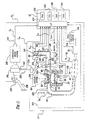
- Direct injection spark ignited internal combustion engine 10 comprising a plurality of combustion chambers, is controlled by electronic engine controller 12.
- Combustion chamber 30 of engine 10 is shown in Figure 1 including combustion chamber walls 32 with piston 36 positioned therein and connected to crankshaft 40.
- piston 30 includes a recess or bowl (not shown) to help in forming stratified charges of air and fuel.
- Combustion chamber 30 is shown communicating with intake manifold 44 and exhaust manifold 48 via respective intake valves 52a and 52b (not shown), and exhaust valves 54a and 54b (not shown).
- Fuel injector 66 is shown directly coupled to combustion chamber 30 for delivering liquid fuel directly therein in proportion to pulse width of signal fpw received from controller 12 via conventional electronic driver 68. Fuel is delivered to fuel injector 66 by a conventional high pressure fuel system (not shown) including a fuel tank, fuel pumps, and a fuel rail.
- Intake manifold 44 is shown communicating with throttle body 58 via throttle plate 62.
- throttle plate 62 is coupled to electric motor 94 so that the position of throttle plate 62 is controlled by controller 12 via electric motor 94.
- This configuration is commonly referred to as electronic throttle control (ETC) which is also utilised during idle speed control.
- ETC electronic throttle control
- a bypass air passageway is arranged in parallel with throttle plate 62 to control inducted airflow during idle speed control via a throttle control valve positioned within the air passageway.
- Exhaust gas oxygen sensor 76 is shown coupled to exhaust manifold 48 upstream of catalytic converter 70.
- sensor 76 provides signal UEGO to controller 12 which converts signal UEGO into a relative air/fuel ratio ⁇ .
- Signal UEGO is used to advantage during feedback air/fuel control in a conventional manner to maintain average air/fuel at a desired air/fuel ratio.
- Conventional distributorless ignition system 88 provides ignition spark to combustion chamber 30 via spark plug 92 in response to spark advance signal SA from controller 12.
- Controller 12 causes combustion chamber 30 to operate in either a homogeneous air/fuel mode or a stratified air/fuel mode by controlling injection timing.
- controller 12 activates fuel injector 66 during the engine compression stroke so that fuel is sprayed directly into the bowl of piston 36. Stratified air/fuel layers are thereby formed. The strata closest to the spark plug contains a stoichiometric mixture or a mixture slightly rich of stoichiometry, and subsequent strata contain progressively leaner mixtures.
- controller 12 activates fuel injector 66 during the intake stroke so that a substantially homogeneous air/fuel mixture is formed when ignition power is supplied to spark plug 92 by ignition system 88.
- Controller 12 controls the amount of fuel delivered by fuel injector 66 so that the homogeneous air/fuel mixture in chamber 30 can be selected to be at stoichiometry, a value rich of stoichiometry, or a value lean of stoichiometry.
- the stratified air/fuel mixture will always be at a value lean of stoichiometry, the exact air/fuel being a function of the amount of fuel delivered to combustion chamber 30.
- An additional split mode of operation wherein additional fuel is injected during the exhaust stroke while operating in the stratified mode is available.
- An additional split mode of operation wherein additional fuel is injected during the intake stroke while operating in the stratified mode is also available, where a combined homogeneous and split mode is available.
- Nitrogen oxide (NOx) absorbent or trap 72 is shown positioned downstream of catalytic converter 70. NOx trap 72 absorbs NOx when engine 10 is operating lean of stoichiometry. The absorbed NOx is subsequently reacted with HC and catalysed during a NOx purge cycle when controller 12 causes engine 10 to operate in either a rich homogeneous mode or a stoichiometric homogeneous mode.
- NOx Nitrogen oxide
- Exhaust gas recirculation tube 120 is also shown coupled between intake manifold 44 and exhaust manifold 48. Exhaust gas recirculation valve 122 is place in exhaust gas recirculation tube 120 to control an amount of recycled exhaust flow. Sensor 124 indicates EGR flow ( ).
- Vacuum brake booster 130 is also shown fluidly communicating with manifold 44 via tube 132.
- Check valve 134 is placed in tube 132 to allow air to pass from vacuum brake booster 130 to manifold 44 only when manifold pressure ( m ) is less than brake booster pressure ( ) .
- check valve 134 allows vacuum to be retained in Vacuum brake booster 130 even when manifold pressure ( ) is higher than brake booster pressure ( ) .
- Vacuum brake booster 130 is also coupled to hydraulic brake system 136 and brake pedal 138. Brake pedal position is measured via sensor 140 and provides signal ( b ) , which represents position of brake pedal 138. In this example, sensor 140 provides a continuous signal that allows determination of brake pedal position throughout an entire span.
- sensor 140 can also provide a switch signal that represents when brake pedal 138 has travelled past a predetermined distance.
- Sensor 142 provides an indication of brake booster pressure ( ) .
- sensor 142 provides a continuous signal that allows determination of brake booster pressure throughout an entire span.
- sensor 142 can also provide a switch signal that represents when brake booster pressure has reached a predetermined value.
- Sensor 144 provides an indication of hydraulic brake pressure ( ).
- sensor 144 provides a continuous signal that allows determination of hydraulic brake pressure throughout an entire span.
- sensor 144 can also provide a switch signal that represents when hydraulic brake pressure has reached a predetermined value.
- Controller 12 is shown in Figure 1 as a conventional microcomputer including: microprocessor unit 102, input/output ports 104, an electronic storage medium for executable programs and calibration values, shown as read-only memory chip 106 in this particular example, random access memory 108, keep alive memory 110, and a conventional data bus.
- Controller 12 is shown receiving various signals from sensors coupled to engine 10, in addition to those signals previously discussed, including: measurement of inducted mass air flow ( ) from mass air flow sensor 100 coupled to throttle body 58, engine coolant temperature (ECT) from temperature sensor 112 coupled to cooling sleeve 114, a profile ignition pickup signal (PIP) from Hall effect sensor 118 coupled to crankshaft 40, throttle position ( ) from throttle position sensor 120, and absolute Manifold Pressure Signal ( ) from sensor 122.
- Engine speed signal ( ⁇ ) is generated by controller 12 from signal PIP in a conventional manner and manifold pressure signal ( ) provides an indication of engine load. Note that the symbol ⁇ is used to specifically indicate a measured variable when necessary, while the symbol ⁇ is used to specifically indicate an estimate when necessary.
- temperature Tcat is provided by temperature sensor 124 and temperature Ttrp is provided by temperature sensor 126.
- temperature sensor 124 is provided by temperature sensor 124 and temperature Ttrp is provided by temperature sensor 126.
- these values may be estimated rather than measured.
- i is an index that occurs at execution of computation loop representing either fixed or variable sample time or engine firings and k is an index representing driving cycles.
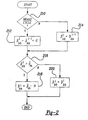
- a routine is described for estimating brake booster pressure from measured manifold pressure ( )and a brake actuation signal.
- step 210 a determination is made as to whether a braking cycle has been completed.
- a braking cycle is determined from brake actuation signal.
- the brake actuation signal can be generated from brake pedal position ( ) , or hydraulic brake pressure ( ). In other words, either of these signals can be used to determine when the brakes have been applied and released and an amount of vacuum has been consumed by vacuum brake booster 130. For example, if brake pedal position ( ) is a switch, cycling of this switch can be used as an indication that a braking cycle has been detected.
- brake pedal position ( ) is a continuous signal, when this signal goes back and forth across a certain level, this can be used to indicate that a braking cycle has been detected. Still other methods can be used for determining brake actuation, such as, for example, hydraulic brake pressure, displacement hydraulic braking actuators, or parameters of electric brake actuators.
- step 212 temporary estimated brake booster pressure ( p and t bb ) is set equal to previously estimated brake booster pressure ( p and i -1 bb ) and predetermined value G.
- Predetermined value G represents an amount of vacuum, or pressure, that is used by vacuum brake booster 130 when actuating the braking system.
- step 214 temporary estimated brake booster pressure ( p and t bb ) is set equal to previously estimated brake booster pressure ( p and i -1 bb ) .
- step 216 a determination is made as to whether temporary estimated brake booster pressure ( p and t bb ) is greater than measured manifold pressure ( ) .
- current estimated brake booster pressure ( p and i bb ) is set equal to measured manifold pressure ( ) minus predetermined value H.
- Predetermined value H represents the pressure drop across check valve 134.
- the current estimated brake booster pressure ( p and i bb ) is set equal to temporary estimated brake booster pressure ( p and t bb ) .
- step 310 a determination is made as to whether a braking cycle has been completed as described previously with respect to step 210.
- the routine continues to step 312 where estimated temporary brake booster pressure ( p and t bb ) is set equal to the previously estimated brake booster pressure ( p and i -1 bb ) and predetermined value G.
- Predetermined value G represents an amount of vacuum, or pressure, that is used by vacuum brake booster 130 when actuating the braking system.
- step 314 temporary estimated brake booster pressure ( p and t bb ) is set equal to the previously estimated brake booster pressure ( p and i -1 bb ) .
- step 315 manifold pressure is estimated from other engine parameters using function g and parameters: , , and ⁇ . Those skilled in the art will recognise various method for estimating manifold pressure these parameters, including modifications for temperature, heat transfer, and various other corrections.
- step 316 a determination is made as to whether temporary estimated brake booster pressure ( p and t bb ) is greater than measured manifold pressure ( ) .
- current estimated brake booster pressure ( p and i bb ) is set equal to the measured manifold pressure ( ) minus predetermined value H.
- Predetermined value H represents the pressure drop across check valve 134.
- the current estimated brake booster pressure ( p and i bb ) is set equal to the temporary estimated brake booster pressure ( p and t bb ).
- estimated brake booster pressure described above herein can be used for engine and vehicle control.
- estimated brake booster pressure can be used to determine a desired combustion mode.
- estimated brake booster pressure can be used to disable lean or stratified combustion when estimated brake booster pressure is greater than a predetermined pressure value.
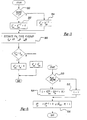
- step 410 a determination is made as to whether measured brake booster pressure () is decreasing. In a preferred embodiment, this is performed by comparing successive measurements of brake booster pressure to one another. When it is determined that brake booster pressure is decreasing, the routine continues to step 412.
- step 412 manifold pressure is estimated based on measured brake booster pressure ( ) and predetermined value H. Predetermined value H represents pressure drop across check valve 134.
- step 412 a flag is set to KNOWN. Otherwise, the routine continues to step 415, where the flag is set to UNKNOWN.
- estimated manifold pressure ( p and m ) can be determined from the brake booster pressure whenever the measured brake booster pressure is decreasing.
- various different filtering techniques can be used such as high pass filtering and low pass filtering.
- limit values can be used to determine when brake booster pressure is decreasing greater than a predetermined value, and only inferring manifold pressure from brake booster pressure when it is decreasing greater than this predetermined value.
- Those skilled in the art will recognized various methods of determining whether a parameter is decreasing, or decreasing by a predetermined amount, or decreasing at a predetermined rate.
- step 510 a determination is made as to whether the flag equals KNOWN. When the answer to step 510 is NO, value L is set equal to zero in step 512. Otherwise, in step 514, value L is determined as a function of measured brake booster pressure ( ) and a previously estimated manifold pressure ( p and i -1 m ) as well as value H.
- the current estimated manifold pressure ( p and i m ) is based on previous estimated manifold pressure ( p and i -1 m ) as well as measured mass airflow ( ) and engine speed ( ⁇ ) and value L.
- manifold pressure using other parameters such as mass airflow and engine speed, and then correct this estimate based on measured brake booster pressure whenever brake booster pressure is decreasing.
- An advantage of this aspect of the present invention is that it is possible to accurately estimate manifold pressure even when brake booster pressure is not decreasing.
- parameters A and B are system parameters which represent the system dynamics and input dynamics as is known to those skilled in the art.
- value L can be learned in memory as a function of engine speed and engine load.
- value L represents the error between the estimate using other variables and the estimate using the brake booster pressure.
- Value L also represents what is known to those skilled in the art as an observer structure.
- function f can be a simple gain, or the sign function, or many other functions known to those skilled in the art of estimators, observers, and modern estimation theory.
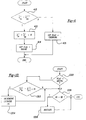
- step 610 a determination is made as to whether a flag equals KNOWN. If the answer to step 610 is YES, the routine continues to step 612, where engine mass airflow is estimated based on measured brake booster pressure ( ) and measured engine speed ( ⁇ ). In step 614, engine speed is estimated based on measured brake booster pressure ( ) and measured mass airflow ( ). In step 616, throttle position is estimated based on measured brake booster ( ) pressure and engine speed ( ⁇ ). In step 618, EGR flow is estimated based on measured brake booster pressure ( ) , measured mass airflow ( ), and measured engine speed ( ⁇ ) .
- measured mass airflow ( ) can also be used to improve the throttle position estimate ( ⁇ and t ) .
- Figure 7A estimates brake system parameters from brake booster pressure.
- a braking cycle it is possible to determine a predicted brake pedal position profile, or a predicted hydraulic brake pressure profile. For example, when a braking cycle is estimated, it is possible to determine that the brake pedal has been depressed by a first predetermined amount and has also been released by a second predetermined amount. Similarly, it is possible to determine that the hydraulic brake pressure reached a first predetermined amount and has also been released by a second predetermined amount
- step 710 a determination is made as to whether measured brake booster pressure is increasing.
- brake booster pressure is increasing when it is greater than a previously measured brake booster pressure and a predetermined value J.
- various other methods for determining whether brake booster pressure is increasing such as, for example, high pass filtering brake booster pressure, comparing the rate of change of brake booster pressure to a limit value rate of change, and various other methods.
- a determination is made as to whether measured brake booster pressure ( ) is relatively constant indicating that the brake actuation is completed.
- the routine determines that a braking cycle has been completed in step 712. In other words, the routine determines brake system operation based on increasing brake booster pressure. Therefore, it is possible to determine whether a braking cycle should have been estimated from other braking system parameters such as, for example, brake pedal position or hydraulic brake pressure. Further it is possible to
- estimated operating parameters described above herein can be used for engine and vehicle control.
- estimated manifold pressure or mass air flow can be used to determine desired fuel injection amounts, fuel injection timings, combustion modes ignition timings, exhaust gas recirculation amounts, and other engine control parameters.
- a fuel injection amount can be adjusted based on estimated airflow or manifold pressure based on the measured brake booster pressure.
- control signals CS1, CS2, and CS3 are calculated using functions h1 , h2, and h3 and estimated parameters, p and m , m and air , and ⁇ and t .
- Control signals CS1, CS2, and CS3 can represent: a desired fuel injection amount, a desired ignition timing amount, a desired fuel injection timing, a desired throttle position, or any other control signal known to those skilled in the art to benefit from information regarding manifold pressure, mass air flow, and/or throttle position.
- step 810 a determination is made as to whether measured brake booster pressure is greater than the sum of measured manifold pressure and predetermined value K1.
- Value K1 represents the maximum amount of pressure drop across a properly functioning check value.
- step 814 a determination is made as to whether counter C1 is greater than limit value El.
- an indication is created in step 814 to indicate possible degradation of sensor 142.
- step 910 a determination is made as to whether a braking cycle has been determined. Braking cycle is determined as described previously herein with reference to step 210.
- step 910 a determination is made as to whether previously measured brake booster pressure with less than previously measured manifold pressure plus predetermined value K2. In other words, a determination is made as to whether if the brakes were cycled between the current measurement and the previous measurement, it would be possible for the brake booster pressure to increase by a measurable amount knowing what the previously measured manifold pressure was.
- step 912 determines whether the current measured manifold pressure is less than the previously measured brake booster pressure. In other words, a determination is made as to whether the current measured manifold pressure has decreased below the previously measured brake booster pressure indicating that it is not possible to determine braking cycles from measured brake booster pressure. Thus, when the answer to step 914 is NO, the routine continues to step 916 to determine whether measured brake booster pressure has increased.
- step 916 conditions are such that a braking cycle should have caused brake booster pressure to increase since brake booster pressure is below manifold pressure.
- the routine continues to step 917 to increment counter C2.
- step 920 a determination is made as to whether counter C2 is greater than limit E2.
- an indication is provided in step 922.
- measured manifold pressure can be replaced in this routine by estimated manifold pressure from sensors such as, for example, engine speed and mass airflow.
- degradation in measured brake booster pressure is determined when brake booster pressure does not approach manifold pressure when measured brake booster pressure is less than measured manifold pressure.
- step 1010 a determination is made as to whether the vehicle has been driven. In other words, whether the vehicle has been started and driven over a predetermined speed or more than a predetermined distance.
- step 1012 a determination is made in step 1012 as to whether measured brake booster pressure is changing. This can be done by determining whether measured brake booster pressure changes by a predetermined amount. This predetermined amount determines that regular sensor noise and variation do not falsely indicate that measured brake booster pressure is properly changing.
- step 1012 is NO, counter C3 is incremented in step 1014.
- step 1016 a determination is made as to whether counter C3 is greater than limit value E3.
- an indication is provided in step 1018.
- counter C4 is reset to zero in step 1020.
- step 1110 a determination is made as to whether the a braking cycle has been detected as described previously herein with respect to step 210.
- step 1110 a determination is made as to whether the a braking cycle has been detected as described previously herein with respect to step 210.
- step 1114 a determination is made as to whether the absolute value of the difference between successive measurements ob measured brake booster pressure after brake cycling is greater than value E5.
- step 1116 a determination is made as to whether measured manifold pressure is greater than value T1.
- step 1116 When the answer to step 1116 is NO, the routine continues to step 1118 where counter C5 is reset. Otherwise, in step 1120, counter C5 is incremented and determined whether it is greater than limit value E6 in step 1122. When the answer to step 1122 is YES, an indication is proceeded in step 1124. In other words, if brake booster pressure is not changing even after actuation of the brakes when manifold pressure is greater than a value T1, degradation is detected.
- step 1210 a determination is made as to whether a braking cycle has been completed as described previously herein with respect to Figure 2 in step 210.
- manifold pressure can be measured from a manifold pressure sensor or estimated using parameters such as engine speed and mass airflow. Alternatively, throttle position and engine speed can be used.
- step 1212 a determination is made as to whether a brake cycling should cause brake booster pressure to approach manifold pressure.
- step 1212 When the answer to step 1212 is NO, counter C5 is reset in step 1216. Otherwise, in step 1214, counter C5 is incremented. Then, in step 1218, a determination is made as to whether counter C5 is greater than limit value E5. When the answer to step 1218 is YES, an indication is provided in step 1220.
- value K2 represents a maximum amount of pressure drop across check valve 134 or a maximum amount of measurement air in both determining manifold pressure and brake booster pressure that can be tolerated.
- step 310 a determination is made as to whether flag equals KNOWN.
- step 1310 a determination is made as to whether the absolute value of the difference between measured manifold pressure and estimated manifold pressure from either step 412 or step 516 is greater than maximum air value F1.
- step 1312 a determination is made as to whether the absolute value of the difference between measured manifold pressure and estimated manifold pressure from either step 412 or step 516 is greater than maximum air value F1.
- step 1312 YES
- counter C6 is incremented in step 1314.
- step 1316 a determination is made as to whether counter C6 is greater than limit value E6.
- an indication is provided in step 1318.
- step 1410 a determination is made as to whether a brake cycle has been estimated as described previously herein with respect to Figure 7.
- the routine continues to step 1412.
- step 1412 a determination is made as to whether brake cycle has been determined from either brake pedal actuation or hydraulic brake pressure measurement as described previously herein with respect Figure 210.
- step 1416 a determination is made as to whether counter C7 is greater than limit value E7.
- step 1418 an indication is provided in step 1418.
- step 1510 a determination is made as to whether flag equal KNOWN.
- step 1512 the absolute value of the difference between measured engine speed and estimated engine speed determined from step 614 is greater than the maximum difference value F2.
- step 1516 a determination is made as to whether counter C8 is greater than limit value E8.
- step 1518 an indication is provided in step 1518.
- step 1610 a determination is made as to whether flag equal KNOWN.
- step 1610 the routine continues to step 1612, where the absolute value of the difference between measured mass air flow and estimated mass air flow determined from step 612 is greater than the maximum difference value F3.
- step 1614 the routine continues to step 1614 and increments counter C9.
- step 1616 a determination is made as to whether counter C9 is greater than limit value E9.
- an indication is provided in step 1618.
- step 1710 a determination is made as to whether flag equal KNOWN.
- step 1710 the routine continues to step 1712, where the absolute value of the difference between measured mass air flow and estimated throttle position determined from step 616 is greater than the maximum difference value F4.
- step 1714 the routine continues to step 1714 and increments counter C10.
- step 1716 a determination is made as to whether counter C10 is greater than limit value E10.
- step 1718 an indication is provided in step 1718.
- step 1810 a determination is made as to whether flag equal KNOWN.
- flag equal KNOWN When the answer to step 1810 is YES, then, as described previously herein, it is possible to estimate exhaust gas recirculation flow from measured brake booster pressure and other operating parameters.
- the routine continues to step 1812, where the absolute value of the difference between measured exhaust gas recirculation flow and estimated exhaust gas recirculation flow determined from step 618 is greater than the maximum difference value F5.
- step 1814 increments counter C11.
- step 1816 a determination is made as to whether counter C11 is greater than limit value E11.
- step 1818 an indication is provided in step 1818.
- step 1910 a determination is made as to whether a brake cycle has been determine from the brake pedal or hydraulic brake pressure as described previously herein with respect to step 210.
- counter C12 is incremented in step 1914.
- step 1916 a determination is made as to whether counter C12 is greater than limit value E12.
- an indication is provided in step 1918.
- estimated manifold pressure is shown using information from both measured airflow and engine speed, and from measured brake booster pressure. Before time t3, manifold pressure is estimated from airflow and engine speed. Then, from time t3 to t4, where the flag is set to KNOWN, both airflow and engine speed and measured brake booster pressure are used. As shown, the estimate from airflow and engine is corrected during this time to improve the accuracy of estimated manifold pressure. Then, after time t4, only airflow and engine are again used.
Landscapes
- Engineering & Computer Science (AREA)
- Mechanical Engineering (AREA)
- Transportation (AREA)
- Chemical & Material Sciences (AREA)
- Combustion & Propulsion (AREA)
- General Engineering & Computer Science (AREA)
- Valves And Accessory Devices For Braking Systems (AREA)
- Control Of Vehicle Engines Or Engines For Specific Uses (AREA)
- Measuring Fluid Pressure (AREA)
Abstract
Description
- The present invention relates to a method and apparatus for monitoring the performance of a sensor used in an automotive vehicle to measure a vehicle or engine operating parameter.
- There are many engine operating conditions that are either measured or estimated to improve internal combustion engine control. For example, manifold pressure is a common internal combustion engine parameter used in various engine control systems. To determine degradation in a manifold pressure sensor, it is known to estimate manifold pressure from engine mass air flow and engine speed along with known engine relationships. It is also common to improve accuracy of this estimated manifold pressure with manifold temperature and exhaust gas recirculation amounts. Then, degradation in the sensor is determined when the estimated value and measured value disagree.
- Conversely, it is also known to estimate mass air flow from manifold pressure. The estimated mass air flow can then be used to determine degradation in the mass air flow sensor. Typically, measured manifold pressure, and also manifold temperature, are used with various predetermined engine maps and engine speed to estimate mass air flow. It is further known to improve accuracy of engine mass air flow by including exhaust gas recirculation amounts.
- In addition, it is also known to use throttle position and engine speed as indications of either mass air flow and/or manifold pressure.
- The inventors herein have recognized a disadvantage with the above approaches. In particular, such estimation methods can have errors due to engine variation, engine ageing, and various other effects. These potential errors can degrade engine performance, fuel economy, and emissions. For example, engine characteristics relating manifold pressure and mass air flow may change from one engine to another. Similarly, engine ageing affects may change heat transfer characteristics, thereby causing errors to arise. Then, premature degradation can be indicated when comparing these estimated values to measured values.
- With a view to mitigating the foregoing disadvantages, there is provided, in accordance with a first aspect of the invention, a method of monitoring the performance of a sensor used to measure a vehicle or engine operating parameter in an automotive vehicle having an internal combustion engine with an intake manifold coupled through a check valve to a brake booster, which method comprises measuring a brake booster pressure, calculating an estimate of the operating parameter based on the brake booster pressure, and determining degradation of the sensor based on a comparison of the measurement of the operating parameter derived from the sensor with the estimate calculated on the basis of the brake booster pressure.
- In accordance with a second aspect of the invention, there is provided an apparatus for monitoring the performance of a sensor used to measure a vehicle or engine operating parameter in an automotive vehicle having an internal combustion engine with an intake manifold coupled through a check valve to a brake booster, the apparatus comprising means for measuring a brake booster pressure, means for calculating an estimate of the engine operating parameter based on the brake booster pressure, and means for determining degradation of the sensor based on the estimate of the engine operating parameter and a predetermined value representing pressure drop across the check valve. Such apparatus may be implemented by a programmed computer.
- By using brake booster pressure, it is possible to provide an improved estimate of other operating parameters. In other words, the present invention recognises the relationships between brake booster pressure and other operating parameters and then uses them to improve estimation. Then, from the improved estimates, more accurate determination of degradation can be realised.
- The invention will now be described further, by way of example, with reference to the accompanying drawings, in which:
- Figure 1 is a block diagram of an embodiment in which the invention is used to advantage,
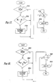
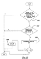
- Figures 2-19 are high level flowcharts describing a portion of operation of the embodiment shown in Figure 1, and
- Figures 20 to 22 are graphs showing examples of operation.
-
- Direct injection spark ignited
internal combustion engine 10, comprising a plurality of combustion chambers, is controlled byelectronic engine controller 12.Combustion chamber 30 ofengine 10 is shown in Figure 1 includingcombustion chamber walls 32 withpiston 36 positioned therein and connected tocrankshaft 40. In this particular example,piston 30 includes a recess or bowl (not shown) to help in forming stratified charges of air and fuel.
Combustion chamber
30 is shown communicating with intake manifold 44 andexhaust manifold 48 viarespective intake valves 52a and 52b (not shown), andexhaust valves 54a and 54b (not shown).Fuel injector 66 is shown directly coupled tocombustion chamber 30 for delivering liquid fuel directly therein in proportion to pulse width of signal fpw received fromcontroller 12 via conventionalelectronic driver 68. Fuel is delivered tofuel injector 66 by a conventional high pressure fuel system (not shown) including a fuel tank, fuel pumps, and a fuel rail. - Intake manifold 44 is shown communicating with
throttle body 58 viathrottle plate 62. In this particular example,throttle plate 62 is coupled toelectric motor 94 so that the position ofthrottle plate 62 is controlled bycontroller 12 viaelectric motor 94. This configuration is commonly referred to as electronic throttle control (ETC) which is also utilised during idle speed control. In an alternative embodiment (not shown), which is well known to those skilled in the art, a bypass air passageway is arranged in parallel withthrottle plate 62 to control inducted airflow during idle speed control via a throttle control valve positioned within the air passageway. - Exhaust
gas oxygen sensor 76 is shown coupled toexhaust manifold 48 upstream ofcatalytic converter 70. In this particular example,sensor 76 provides signal UEGO to controller 12 which converts signal UEGO into a relative air/fuel ratio λ. Signal UEGO is used to advantage during feedback air/fuel control in a conventional manner to maintain average air/fuel at a desired air/fuel ratio. - Conventional
distributorless ignition system 88 provides ignition spark tocombustion chamber 30 viaspark plug 92 in response to spark advance signal SA fromcontroller 12. -
Controller 12 causescombustion chamber 30 to operate in either a homogeneous air/fuel mode or a stratified air/fuel mode by controlling injection timing. In the stratified mode,controller 12 activatesfuel injector 66 during the engine compression stroke so that fuel is sprayed directly into the bowl ofpiston 36. Stratified air/fuel layers are thereby formed. The strata closest to the spark plug contains a stoichiometric mixture or a mixture slightly rich of stoichiometry, and subsequent strata contain progressively leaner mixtures. During the homogeneous mode,controller 12 activatesfuel injector 66 during the intake stroke so that a substantially homogeneous air/fuel mixture is formed when ignition power is supplied tospark plug 92 byignition system 88.Controller 12 controls the amount of fuel delivered byfuel injector 66 so that the homogeneous air/fuel mixture inchamber 30 can be selected to be at stoichiometry, a value rich of stoichiometry, or a value lean of stoichiometry. The stratified air/fuel mixture will always be at a value lean of stoichiometry, the exact air/fuel being a function of the amount of fuel delivered tocombustion chamber 30. An additional split mode of operation wherein additional fuel is injected during the exhaust stroke while operating in the stratified mode is available. An additional split mode of operation wherein additional fuel is injected during the intake stroke while operating in the stratified mode is also available, where a combined homogeneous and split mode is available. - Nitrogen oxide (NOx) absorbent or
trap 72 is shown positioned downstream ofcatalytic converter 70.NOx trap 72 absorbs NOx whenengine 10 is operating lean of stoichiometry. The absorbed NOx is subsequently reacted with HC and catalysed during a NOx purge cycle whencontroller 12 causesengine 10 to operate in either a rich homogeneous mode or a stoichiometric homogeneous mode. - Exhaust
gas recirculation tube 120 is also shown coupled between intake manifold 44 andexhaust manifold 48. Exhaustgas recirculation valve 122 is place in exhaustgas recirculation tube 120 to control an amount of recycled exhaust flow.Sensor 124 indicates EGR flow ().
-
Vacuum brake booster 130 is also shown fluidly communicating with manifold 44 viatube 132.Check valve 134 is placed intube 132 to allow air to pass fromvacuum brake booster 130 to manifold 44 only when manifold pressure ( m ) is less than brake booster pressure () . Thus,
check valve 134 allows vacuum to be retained inVacuum brake booster 130 even when manifold pressure () is higher than brake booster pressure ( ) .
) .
Vacuum brake booster 130 is also coupled tohydraulic brake system 136 andbrake pedal 138. Brake pedal position is measured viasensor 140 and provides signal (b) , which represents position of
brake pedal 138. In this example,sensor 140 provides a continuous signal that allows determination of brake pedal position throughout an entire span. However,sensor 140 can also provide a switch signal that represents whenbrake pedal 138 has travelled past a predetermined distance.Sensor 142 provides an indication of brake booster pressure () . In this example,
sensor 142 provides a continuous signal that allows determination of brake booster pressure throughout an entire span. However,sensor 142 can also provide a switch signal that represents when brake booster pressure has reached a predetermined value.Sensor 144 provides an indication of hydraulic brake pressure (). In this example,
sensor 144 provides a continuous signal that allows determination of hydraulic brake pressure throughout an entire span. However,sensor 144 can also provide a switch signal that represents when hydraulic brake pressure has reached a predetermined value. -
Controller 12 is shown in Figure 1 as a conventional microcomputer including:microprocessor unit 102, input/output ports 104, an electronic storage medium for executable programs and calibration values, shown as read-only memory chip 106 in this particular example,random access memory 108, keepalive memory 110, and a conventional data bus. -
Controller 12 is shown receiving various signals from sensors coupled toengine 10, in addition to those signals previously discussed, including: measurement of inducted mass air flow () from mass
air flow sensor 100 coupled to throttlebody 58, engine coolant temperature (ECT) fromtemperature sensor 112 coupled to coolingsleeve 114, a profile ignition pickup signal (PIP) fromHall effect sensor 118 coupled tocrankshaft 40, throttle position () from
throttle position sensor 120, and absolute Manifold Pressure Signal () from
sensor 122. Engine speed signal (Ñ) is generated bycontroller 12 from signal PIP in a conventional manner and manifold pressure signal () provides an indication of engine load. Note that the symbol ~ is used to specifically indicate a measured variable when necessary, while the symbol ^ is used to specifically indicate an estimate when necessary.
- In this particular example, temperature Tcat is provided by
temperature sensor 124 and temperature Ttrp is provided by temperature sensor 126. However, those skilled in the art will recognise that these values may be estimated rather than measured. - Also, i is an index that occurs at execution of computation loop representing either fixed or variable sample time or engine firings and k is an index representing driving cycles.
- The following figures describe methods for estimating brake booster pressure based on other parameters.
- Referring now to Figure 2, a routine is described for estimating brake booster pressure from measured manifold pressure ()and a brake actuation signal. In

step 210, a determination is made as to whether a braking cycle has been completed. A braking cycle is determined from brake actuation signal. The brake actuation signal can be generated from brake pedal position () , or hydraulic brake pressure ( ). In other words, either of these signals can be used to determine when the brakes have been applied and released and an amount of vacuum has been consumed by
vacuum brake booster 130. For example, if brake pedal position () is a switch, cycling of this switch can be used as an indication that a braking cycle has been detected. Further, if brake pedal position ( ) is a continuous signal, when this signal goes back and forth across a certain level, this can be used to indicate that a braking cycle has been detected. Still other methods can be used for determining brake actuation, such as, for example, hydraulic brake pressure, displacement hydraulic braking actuators, or parameters of electric brake actuators.
- Continuing with Figure 2, when a braking cycle has been detected, the routine continues to step 212 where temporary estimated brake booster pressure (p and t bb ) is set equal to previously estimated brake booster pressure ( p and i-1 bb ) and predetermined value G. Predetermined value G represents an amount of vacuum, or pressure, that is used by
vacuum brake booster 130 when actuating the braking system. Otherwise, instep 214, temporary estimated brake booster pressure ( p and t bb ) is set equal to previously estimated brake booster pressure ( p and i-1 bb ) . Next, instep 216, a determination is made as to whether temporary estimated brake booster pressure ( p and t bb ) is greater than measured manifold pressure () . When the answer to step 216 is YES, current estimated brake booster pressure ( p and i bb ) is set equal to measured manifold pressure ( ) minus predetermined value H. Predetermined value H represents the pressure drop across
check valve 134. Otherwise, instep 220, the current estimated brake booster pressure ( p and i bb ) is set equal to temporary estimated brake booster pressure ( p and t bb ) . Thus, it is possible to estimate brake booster pressure using other operating parameters. In particular, by including the pressure drop across the valve, a more accurate estimate is provided. - Referring now to Figure 3, a routine is described for estimating brake booster pressure using braking system parameters and an estimated manifold pressure ( p andm ) . In
step 310, a determination is made as to whether a braking cycle has been completed as described previously with respect to step 210. When a braking cycle has been detected, the routine continues to step 312 where estimated temporary brake booster pressure ( p and t bb ) is set equal to the previously estimated brake booster pressure (p and i-1 bb ) and predetermined value G. Predetermined value G represents an amount of vacuum, or pressure, that is used byvacuum brake booster 130 when actuating the braking system. Otherwise, instep 314, temporary estimated brake booster pressure ( p and t bb ) is set equal to the previously estimated brake booster pressure (p and i-1 bb ) . Instep 315, manifold pressure is estimated from other engine parameters using function g and parameters:
, , and Ñ. Those skilled in the art will recognise various method for estimating manifold pressure these parameters, including modifications for temperature, heat transfer, and various other corrections.
- Next, in step 316, a determination is made as to whether temporary estimated brake booster pressure ( p and t bb ) is greater than measured manifold pressure () . When the answer to step 316 is YES, current estimated brake booster pressure ( p andi bb ) is set equal to the measured manifold pressure (
 ) minus predetermined value H. Predetermined value H represents the pressure drop across
check valve 134. Otherwise, in step 320, the current estimated brake booster pressure ( p and i bb ) is set equal to the temporary estimated brake booster pressure ( p and t bb ). Thus, it is possible to estimate brake booster pressure using other operating parameters. - The estimated brake booster pressure described above herein can be used for engine and vehicle control. For example, estimated brake booster pressure can be used to determine a desired combustion mode. In particular, estimated brake booster pressure can be used to disable lean or stratified combustion when estimated brake booster pressure is greater than a predetermined pressure value.
- Those skilled in the art will recognized in view of this disclosure, that the methods for estimating brake booster pressure can also be used to improved measurements of brake booster pressure. Thus, improved accuracy can be obtained.
- The following figures describe methods according to the present invention for estimating parameters based on brake booster pressure.
- Referring now to Figure 4, a routine is described for estimating manifold pressure based on brake booster pressure. First, in
step 410, a determination is made as to whether measured brake booster pressure() is decreasing. In a preferred embodiment, this is performed by comparing successive measurements of brake booster pressure to one another. When it is determined that brake booster pressure is decreasing, the routine continues to step 412. In
step 412, manifold pressure is estimated based on measured brake booster pressure () and predetermined value H. Predetermined value H represents pressure drop across
check valve 134. Next, instep 412, a flag is set to KNOWN. Otherwise, the routine continues to step 415, where the flag is set to UNKNOWN. In other words, estimated manifold pressure ( p andm ) can be determined from the brake booster pressure whenever the measured brake booster pressure is decreasing. Those skilled in the art will recognise various other methods of determining if brake booster pressure is decreasing. For example, various different filtering techniques can be used such as high pass filtering and low pass filtering. Also, limit values can be used to determine when brake booster pressure is decreasing greater than a predetermined value, and only inferring manifold pressure from brake booster pressure when it is decreasing greater than this predetermined value. Those skilled in the art will recognized various methods of determining whether a parameter is decreasing, or decreasing by a predetermined amount, or decreasing at a predetermined rate. - Referring now to Figure 5, a routine is described for estimating manifold pressure based on measured brake booster pressure as well as other parameters. First, in
step 510, a determination is made as to whether the flag equals KNOWN. When the answer to step 510 is NO, value L is set equal to zero instep 512. Otherwise, instep 514, value L is determined as a function of measured brake booster pressure () and a previously estimated manifold pressure (p and i-1 m ) as well as value H. Then, in
step 516, the current estimated manifold pressure ( p and i m ) is based on previous estimated manifold pressure ( p and i-1 m ) as well as measured mass airflow () and engine speed (Ñ) and value L. Thus, it is possible to estimate manifold pressure using other parameters such as mass airflow and engine speed, and then correct this estimate based on measured brake booster pressure whenever brake booster pressure is decreasing. An advantage of this aspect of the present invention is that it is possible to accurately estimate manifold pressure even when brake booster pressure is not decreasing. Also, parameters A and B are system parameters which represent the system dynamics and input dynamics as is known to those skilled in the art. Also, value L can be learned in memory as a function of engine speed and engine load. Again, value L represents the error between the estimate using other variables and the estimate using the brake booster pressure. Value L also represents what is known to those skilled in the art as an observer structure. Also, function f can be a simple gain, or the sign function, or many other functions known to those skilled in the art of estimators, observers, and modern estimation theory.
- Referring now to Figure 6, a routine is described for estimating other engine operating parameters based on measured brake booster pressure (). First, in

step 610, a determination is made as to whether a flag equals KNOWN. If the answer to step 610 is YES, the routine continues to step 612, where engine mass airflow is estimated based on measured brake booster pressure () and measured engine speed (Ñ). In
step 614, engine speed is estimated based on measured brake booster pressure () and measured mass airflow ( ). In
). In
step 616, throttle position is estimated based on measured brake booster () pressure and engine speed (Ñ). In
step 618, EGR flow is estimated based on measured brake booster pressure () , measured mass airflow ( ), and measured engine speed (Ñ) . Those skilled in the art will recognise various other combinations, equations, and approaches for estimating engine operating parameters based on measured brake booster pressure in view of the present invention. For example, in
step 616, measured mass airflow () can also be used to improve the throttle position estimate ( and t ) .
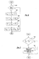
- Figure 7A estimates brake system parameters from brake booster pressure. In other words, when a braking cycle is estimated, it is possible to determine a predicted brake pedal position profile, or a predicted hydraulic brake pressure profile. For example, when a braking cycle is estimated, it is possible to determine that the brake pedal has been depressed by a first predetermined amount and has also been released by a second predetermined amount. Similarly, it is possible to determine that the hydraulic brake pressure reached a first predetermined amount and has also been released by a second predetermined amount
- Referring now to Figure 7A, in
step 710, a determination is made as to whether measured brake booster pressure is increasing. In this particular example, brake booster pressure is increasing when it is greater than a previously measured brake booster pressure and a predetermined value J. However, those skilled in the art will recognise various other methods for determining whether brake booster pressure is increasing such as, for example, high pass filtering brake booster pressure, comparing the rate of change of brake booster pressure to a limit value rate of change, and various other methods. When the answer to step 710 is YES, a determination is made as to whether measured brake booster pressure () is relatively constant indicating that the brake actuation is completed. When the answer to step 711 is YES, the routine determines that a braking cycle has been completed in
step 712. In other words, the routine determines brake system operation based on increasing brake booster pressure. Therefore, it is possible to determine whether a braking cycle should have been estimated from other braking system parameters such as, for example, brake pedal position or hydraulic brake pressure. Further it is possible to - The estimated operating parameters described above herein can be used for engine and vehicle control. For example, estimated manifold pressure or mass air flow can be used to determine desired fuel injection amounts, fuel injection timings, combustion modes ignition timings, exhaust gas recirculation amounts, and other engine control parameters. For example, to maintain a desired air/fuel ratio, a fuel injection amount can be adjusted based on estimated airflow or manifold pressure based on the measured brake booster pressure.
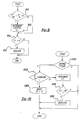
- Referring now to Figure 7B, a routine is described for calculating control signals based on estimated parameters, where the estimated parameters are based on measured brake booster pressure. In
step 750, control signals CS1, CS2, and CS3 are calculated using functions h1, h2, and h3 and estimated parameters, p andm , m andair , and and t . Control signals CS1, CS2, and CS3 can represent: a desired fuel injection amount, a desired ignition timing amount, a desired fuel injection timing, a desired throttle position, or any other control signal known to those skilled in the art to benefit from information regarding manifold pressure, mass air flow, and/or throttle position. - The following figures describe various methods that can be used alone or in combination to determine degradation of brake
booster pressure sensor 142. - Referring now to Figure 8, a routine is described for determining degradation of brake
booster pressure sensor 142 based on measured manifold pressure. The routine assumes that a check valve is properly operating. First, instep 810, a determination is made as to whether measured brake booster pressure is greater than the sum of measured manifold pressure and predetermined value K1. Value K1 represents the maximum amount of pressure drop across a properly functioning check value. When the answer to step 810 is YES, counter C1 is incremented instep 812. Next, instep 814, a determination is made as to whether counter C1 is greater than limit value El. When the answer to step 814 is YES, an indication is created instep 814 to indicate possible degradation ofsensor 142. Thus, it is possible to determine degradation of brake booster pressure sensor based on measured manifold pressure. In other words, sincecheck valve 134 only allows brake booster pressure to be less than manifold pressure, degradation is determined when measured brake booster pressure is greater than an allowable maximum level based on manifold pressure. Thus degradation in measured brake booster pressure can be accurately determined. - Referring now to Figure 9, a routine for determining degradation in brake
booster pressure sensor 142 based on an indicated brake cycle is described. First, instep 910, a determination is made as to whether a braking cycle has been determined. Braking cycle is determined as described previously herein with reference to step 210. Next, when the answer to step 910 is YES, a determination is made as to whether previously measured brake booster pressure with less than previously measured manifold pressure plus predetermined value K2. In other words, a determination is made as to whether if the brakes were cycled between the current measurement and the previous measurement, it would be possible for the brake booster pressure to increase by a measurable amount knowing what the previously measured manifold pressure was. If it is not possible for the brake booster pressure to increase due to a braking cycle because of low manifold pressure andcheck valve 134, then the answer to step 912 is NO. Otherwise, when the answer to step 912 is YES, a determination is made instep 914 as to whether the current measured manifold pressure is less than the previously measured brake booster pressure. In other words, a determination is made as to whether the current measured manifold pressure has decreased below the previously measured brake booster pressure indicating that it is not possible to determine braking cycles from measured brake booster pressure. Thus, when the answer to step 914 is NO, the routine continues to step 916 to determine whether measured brake booster pressure has increased. In other words, instep 916, conditions are such that a braking cycle should have caused brake booster pressure to increase since brake booster pressure is below manifold pressure. When brake booster pressure is not increasing, the routine continues to step 917 to increment counter C2. Next, instep 920, a determination is made as to whether counter C2 is greater than limit E2. When the answer to step 920 is YES, an indication is provided instep 922. Thus, it is possible to determine degradation in measured brakebooster pressure sensor 142 based on measured manifold pressure and a determination of brake cycling. Those skilled in the art will recognise that measured manifold pressure can be replaced in this routine by estimated manifold pressure from sensors such as, for example, engine speed and mass airflow. Thus, degradation in measured brake booster pressure is determined when brake booster pressure does not approach manifold pressure when measured brake booster pressure is less than measured manifold pressure. - Referring now to Figure 10, a routine is described for determining degradation in brake
booster pressure sensor 142 based on vehicle operation. First, instep 1010, a determination is made as to whether the vehicle has been driven. In other words, whether the vehicle has been started and driven over a predetermined speed or more than a predetermined distance. When the answer to step 1010 is YES, a determination is made instep 1012 as to whether measured brake booster pressure is changing. This can be done by determining whether measured brake booster pressure changes by a predetermined amount. This predetermined amount determines that regular sensor noise and variation do not falsely indicate that measured brake booster pressure is properly changing. When the answer to step 1012 is NO, counter C3 is incremented in step 1014. Next, instep 1016, a determination is made as to whether counter C3 is greater than limit value E3. When the answer to step 1016 is YES, an indication is provided instep 1018. Continuing with Figure 10, when the answer to step 1012 is YES, counter C4 is reset to zero instep 1020. Thus, it is possible to determine degradation and measured brake booster pressure knowing that brake booster pressure should change if the vehicle has been driven. Therefore, it is also possible to detect in range sensor degradation. - Referring now to Figure 11, a routine is described for determining degradation in brake
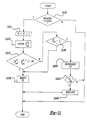
booster pressure sensor 142 based on braking operation. First, instep 1110, a determination is made as to whether the a braking cycle has been detected as described previously herein with respect to step 210. When the answer to step 1110 is YES, braking cycle parameter k is incremented and the measured brake booster pressure at this step is stored as () insteps step 1114, a determination is made as to whether the absolute value of the difference between successive measurements ob measured brake booster pressure after brake cycling is greater than value E5. When the answer to step 1114 is NO, the routine continues to step 1116. Instep 1116, a determination is made as to whether measured manifold pressure is greater than value T1. When the answer to step 1116 is NO, the routine continues to step 1118 where counter C5 is reset. Otherwise, instep 1120, counter C5 is incremented and determined whether it is greater than limit value E6 instep 1122. When the answer to step 1122 is YES, an indication is proceeded instep 1124. In other words, if brake booster pressure is not changing even after actuation of the brakes when manifold pressure is greater than a value T1, degradation is detected. - Referring now to Figure 12, a routine is described for determining degradation in measured brake booster pressure based on braking cycles. First, in
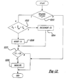
step 1210, a determination is made as to whether a braking cycle has been completed as described previously herein with respect to Figure 2 instep 210. When the answer to step 1210 is YES, a determination is made as to whether measured brake booster pressure plus a predetermined value K2 is less than manifold pressure. Those skilled in the art will recognise that manifold pressure can be measured from a manifold pressure sensor or estimated using parameters such as engine speed and mass airflow. Alternatively, throttle position and engine speed can be used. In other words, instep 1212, a determination is made as to whether a brake cycling should cause brake booster pressure to approach manifold pressure. When the answer to step 1212 is NO, counter C5 is reset instep 1216. Otherwise, instep 1214, counter C5 is incremented. Then, in step 1218, a determination is made as to whether counter C5 is greater than limit value E5. When the answer to step 1218 is YES, an indication is provided instep 1220. Thus, degradation in measured brake booster pressure is determined when brake booster pressure does not approach manifold pressure even after a predetermined number of braking cycles. Thus, value K2 represents a maximum amount of pressure drop acrosscheck valve 134 or a maximum amount of measurement air in both determining manifold pressure and brake booster pressure that can be tolerated. - The following figures describe various methods that can be used alone or in combination to determine degradation of operating parameter sensors based on measured brake booster pressure.
- Referring now to Figure 13, a routine is described for determining degradation of
manifold pressure sensor 122 based on measured brake booster pressure. First, instep 310, a determination is made as to whether flag equals KNOWN. When the answer to step 1310 is YES, the routine continues to step 1312 where a determination is made as to whether the absolute value of the difference between measured manifold pressure and estimated manifold pressure from either step 412 or step 516 is greater than maximum air value F1. When the answer to step 1312 is YES, counter C6 is incremented instep 1314. Continuing with Figure 13, instep 1316, a determination is made as to whether counter C6 is greater than limit value E6. When the answer to step 1316 is YES, an indication is provided instep 1318. Thus, it is possible to determine degradation ofmanifold pressure sensor 122 based on brakebooster pressure sensor 142. In particular, even without estimating manifold pressure from measured mass airflow and engine speed or measured throttle position and engine speed, it is still possible to determine degradation ofpressure sensor 122 by using measured brake booster pressure whenever measured brake booster pressure is decreasing. - Referring now to Figure 14, a routine is described for determining degradation in either brake pedal sensor or hydraulic brake pressure sensor using estimated brake cycling as described previously herein with respect to Figure 7. First, in
step 1410, a determination is made as to whether a brake cycle has been estimated as described previously herein with respect to Figure 7. When the answer to step 1410 is YES, the routine continues to step 1412. Instep 1412, a determination is made as to whether brake cycle has been determined from either brake pedal actuation or hydraulic brake pressure measurement as described previously herein with respect Figure 210. When the answer to step 1412 is NO, counter C7 is incremented instep 1414. Next, instep 1416, a determination is made as to whether counter C7 is greater than limit value E7. When the answer to step 1416 is YES, an indication is provided instep 1418. Thus, it is possible to determine degradation in brake system sensors, such as brake pedal position or hydraulic brake pressure, based on measured brake booster pressure. - Referring now to Figure 15, a routine is described for determining degradation in measured engine speed based on measured brake booster pressure. First, in
step 1510, a determination is made as to whether flag equal KNOWN. When the answer to step 1510 is YES, then, as described previously herein, it is possible to estimate engine speed from measured brake booster pressure and other operating parameters. When the answer to step 1510 is YES, the routine continues to step 1512, where the absolute value of the difference between measured engine speed and estimated engine speed determined fromstep 614 is greater than the maximum difference value F2. When the answer to step 1512 is YES, the routine continues to step 1514 and increments counter C8. Next, instep 1516, a determination is made as to whether counter C8 is greater than limit value E8. When the answer to step 1516 is YES, an indication is provided instep 1518. Thus, engine speed estimated from brake booster pressure whenever brake booster pressure is decreasing is used along with measured mass airflow to determine degradation in engine speed sensing. - Referring now to Figure 16, a routine is described for determining degradation in measured mass airflow based on measured brake booster pressure. First, in
step 1610, a determination is made as to whether flag equal KNOWN. When the answer to step 1610 is YES, then, as described previously herein, it is possible to estimate mass air flow from measured brake booster pressure and other operating parameters. When the answer to step 1610 is YES, the routine continues to step 1612, where the absolute value of the difference between measured mass air flow and estimated mass air flow determined fromstep 612 is greater than the maximum difference value F3. When the answer to step 1612 is YES, the routine continues to step 1614 and increments counter C9. Next, instep 1616, a determination is made as to whether counter C9 is greater than limit value E9. When the answer to step 1616 is YES, an indication is provided instep 1618. Thus, mass air flow estimated from brake booster pressure whenever brake booster pressure is decreasing is used along with measured engine speed to determine degradation in mass airflow sensing. - Referring now to Figure 17, a routine is described for determining degradation in throttle position based on measured brake booster pressure. First, in
step 1710, a determination is made as to whether flag equal KNOWN. When the answer to step 1710 is YES, then, as described previously herein, it is possible to estimate throttle position from measured brake booster pressure and other operating parameters. When the answer to step 1710 is YES, the routine continues to step 1712, where the absolute value of the difference between measured mass air flow and estimated throttle position determined fromstep 616 is greater than the maximum difference value F4. When the answer to step 1712 is YES, the routine continues to step 1714 and increments counter C10. Next, instep 1716, a determination is made as to whether counter C10 is greater than limit value E10. When the answer to step 1716 is YES, an indication is provided instep 1718. Thus, throttle position estimated from brake booster pressure whenever brake booster pressure is decreasing is used along with measured engine speed to determine degradation in throttle position sensing. - Referring now to Figure 18, a routine is described for determining degradation in exhaust gas recirculation flow sensing based on measured brake booster pressure. First, in
step 1810, a determination is made as to whether flag equal KNOWN. When the answer to step 1810 is YES, then, as described previously herein, it is possible to estimate exhaust gas recirculation flow from measured brake booster pressure and other operating parameters. When the answer to step 1810 is YES, the routine continues to step 1812, where the absolute value of the difference between measured exhaust gas recirculation flow and estimated exhaust gas recirculation flow determined fromstep 618 is greater than the maximum difference value F5. When the answer to step 1812 is YES, the routine continues to step 1814 and increments counter C11. Next, instep 1816, a determination is made as to whether counter C11 is greater than limit value E11. When the answer to step 1816 is YES, an indication is provided instep 1818. Thus, exhaust gas recirculation flow estimated from brake booster pressure whenever brake booster pressure is decreasing is used along with measured mass air flow and measured engine speed to determine degradation in exhaust gas recirculation flow sensing. - Referring now to Figure 19, a routine for determine degradation in either brake
pedal position sensor 140 orhydraulic brake pressure 144 is described. First, instep 1910, a determination is made as to whether a brake cycle has been determine from the brake pedal or hydraulic brake pressure as described previously herein with respect to step 210. When the answer to step 1910 is YES, a determine is made instep 1912 as to whether a braking cycle has been estimated from measured brake booster pressure as previously described herein with respect to Figure 7. When the answer to step 1912 is NO, counter C12 is incremented instep 1914. Next, in step 1916, a determination is made as to whether counter C12 is greater than limit value E12. When the answer to step 1916 is YES, an indication is provided instep 1918. Thus, it is possible to detect degradation in either brakepedal position sensor 140 or hydraulic brake pressure sensor from measuredbrake booster pressure 144. - The following figures describe graphs showing examples of operation according to the present invention as described above herein.
- In Figure 20, measured manifold pressure is shown with the estimated brake booster pressure under normal operating conditions. The pressure drop across the check valve H is indicated as well as the increase in pressure due to predetermined value G. Before time t0, brake booster pressure is estimate directly from manifold pressure and H since manifold pressure is decreasing. Then, at time t1, the brakes are actuated. Then, at time t2, the brakes are released and it is determined that the brakes have been cycled and a predetermined value G is used to represent the vacuum (or pressure) used by the brake booster.
- In Figure 21, estimated manifold pressure is shown using information from both measured airflow and engine speed, and from measured brake booster pressure. Before time t3, manifold pressure is estimated from airflow and engine speed. Then, from time t3 to t4, where the flag is set to KNOWN, both airflow and engine speed and measured brake booster pressure are used. As shown, the estimate from airflow and engine is corrected during this time to improve the accuracy of estimated manifold pressure. Then, after time t4, only airflow and engine are again used.
- In Figure 22, degradation of measured brake booster pressure is described. At times t5, t6, t7, and t8, a braking cycle is completed as indicated from
brake pedal 140. As shown, measured brake booster pressure does not increase during any of these braking cycles even though manifold pressure is greater than the measured brake booster pressure. Thus, during each of these times, a counter increments. At time t8, the counter has reached the calibrated level and an indication of degradation is provided. - This concludes a description of an example in which the invention is used to advantage. Those skilled in the art will recognise that many modifications may be practised without departing from the scope of the invention as set forth in the appended claims. For example, the present invention can be used as a supplement to exiting methods for estimating operating parameters and, or, determining degradation. Also, the methods are not limited to gasoline engines, but can be used with diesel engines, alternatively fuelled engines, or hybrid powertrains.
Claims (10)
- A method of monitoring the performance of a sensor used to measure a vehicle or engine operating parameter in an automotive vehicle having an internal combustion engine with an intake manifold coupled through a check valve to a brake booster, the method comprising:measuring a brake booster pressure,calculating an estimate of the operating parameter based on the brake booster pressure, anddetermining degradation of the sensor based on a comparison of the measurement of the operating parameter derived from the sensor with the estimate calculated on the basis of the brake booster pressure.
- A method as claimed in Claim 1, wherein the operating parameter is a pressure in the intake manifold.
- A method as claimed in Claim 1, wherein the operating parameter is an air mass flow.
- A method as claimed in Claim 3, wherein the operating parameter is an air mass flow entering the engine.
- A method as claimed in Claim 3, wherein the operating parameter is an air mass flow entering the intake manifold.
- A method as claimed in Claim 1, wherein the operating parameter is a throttle position of a throttle coupled to the intake manifold.
- A method as claimed in any preceding claim, wherein the calculating step comprises calculating the estimate of the operating parameter based on the brake booster pressure when the brake booster pressure is increasing and/or decreasing.
- A method as claimed in any preceding claim, wherein the calculating step comprises calculating the estimate of the operating parameter based on the brake booster pressure and a predetermined pressure drop across the check valve.
- Apparatus for monitoring the performance of a sensor used to measure a vehicle or engine operating parameter in an automotive vehicle having an internal combustion engine with an intake manifold coupled through a check valve to a brake booster, the apparatus comprising:means for measuring a brake booster pressure,means for calculating an estimate of the engine operating parameter based on the brake booster pressure, andmeans for determining degradation of the sensor based on the estimate of the engine operating parameter and a predetermined value representing pressure drop across the check valve-.
- Apparatus as claimed in claim 9, wherein operating parameter at least one of the group comprising the pressure in the manifold, a mass air flow and the position of a throttle coupled to the intake manifold.
Applications Claiming Priority (2)
| Application Number | Priority Date | Filing Date | Title |
|---|---|---|---|
| US479858 | 1990-02-14 | ||
| US09/479,858 US6393345B1 (en) | 2000-01-07 | 2000-01-07 | Method for estimation |
Publications (3)
| Publication Number | Publication Date |
|---|---|
| EP1114926A2 true EP1114926A2 (en) | 2001-07-11 |
| EP1114926A3 EP1114926A3 (en) | 2003-01-02 |
| EP1114926B1 EP1114926B1 (en) | 2005-11-16 |
Family
ID=23905724
Family Applications (1)
| Application Number | Title | Priority Date | Filing Date |
|---|---|---|---|
| EP00311483A Expired - Lifetime EP1114926B1 (en) | 2000-01-07 | 2000-12-20 | Sensor performance monitoring |
Country Status (3)
| Country | Link |
|---|---|
| US (1) | US6393345B1 (en) |
| EP (1) | EP1114926B1 (en) |
| DE (1) | DE60024048T2 (en) |
Cited By (2)
| Publication number | Priority date | Publication date | Assignee | Title |
|---|---|---|---|---|
| EP1295771A3 (en) * | 2001-09-11 | 2005-06-01 | Siemens Aktiengesellschaft | Method for controlling the pressure in a vacuum brake booster |
| CN107407225A (en) * | 2015-02-27 | 2017-11-28 | 五十铃自动车株式会社 | Diagnostic device and diagnostic system |
Families Citing this family (20)
| Publication number | Priority date | Publication date | Assignee | Title |
|---|---|---|---|---|
| US6871918B2 (en) * | 1999-07-30 | 2005-03-29 | Robert Bosch Gmbh | Method for the reliable operation of a brake booster system, brake booster system, and circuit therefor for implementing the method |
| US6493617B1 (en) * | 2000-01-07 | 2002-12-10 | Ford Global Technologies, Inc. | Lean burn engine with brake system |
| US6880532B1 (en) | 2000-01-07 | 2005-04-19 | Ford Global Technologies, Llc | Engine operation parameter estimation method |
| US6990858B2 (en) * | 2000-01-07 | 2006-01-31 | Ford Global Technologies, Llc | System and method for detection of degradation of vacuum brake booster sensor |
| US6877367B2 (en) * | 2000-05-17 | 2005-04-12 | Horiba, Ltd. | System and method for measuring brake mean effective pressure in a running vehicle |
| DE10037569B4 (en) * | 2000-08-02 | 2014-02-13 | Robert Bosch Gmbh | Method, computer program and control device for determining the air mass, which is supplied to an internal combustion engine via an intake pipe |
| US6848418B1 (en) | 2003-11-10 | 2005-02-01 | Ford Global Technologies, Llc | External exhaust gas recirculation on board diagnostic using EGR effect on a combination of engine operating parameters |
| US7040719B2 (en) * | 2004-04-01 | 2006-05-09 | General Motors Corporation | Brake booster vacuum prediction algorithm and method of use therefor |
| US7367188B2 (en) * | 2006-07-28 | 2008-05-06 | Ford Global Technologies, Llc | System and method for diagnostic of low pressure exhaust gas recirculation system and adapting of measurement devices |
| DE102007009689B4 (en) * | 2007-02-28 | 2017-10-19 | Robert Bosch Gmbh | Method for operating an internal combustion engine with exhaust gas recirculation |
| US20080238189A1 (en) * | 2007-03-27 | 2008-10-02 | Kuo Ching-Chuang G | System and method for vacuum booster assist |
| US7967720B2 (en) * | 2007-06-13 | 2011-06-28 | Ford Global Technologies, Llc | Dynamic allocation of drive torque |
| DE102011110699A1 (en) * | 2011-08-16 | 2013-02-21 | GM Global Technology Operations LLC (n. d. Gesetzen des Staates Delaware) | Method for controlling internal combustion engine of motor vehicle, involves detecting operating condition, in which brake force booster is evacuated and additional air mass flow is directed from brake force booster in intake tract |
| DE102012201436A1 (en) * | 2012-02-01 | 2013-08-01 | Robert Bosch Gmbh | A brake operation detecting apparatus and method for detecting an operation of a brake operating member of a brake system |
| US8978456B2 (en) | 2012-11-16 | 2015-03-17 | Ford Global Technologies, Llc | Brake booster fault diagnostics |
| US9797329B2 (en) | 2014-11-07 | 2017-10-24 | Ford Global Technologies, Llc | Method for diagnosing a vacuum actuator |
| CN111379639B (en) * | 2018-12-28 | 2022-07-01 | 联合汽车电子有限公司 | Method for estimating air flow in brake pump inflow manifold during braking |
| DE102020135055A1 (en) | 2019-12-30 | 2021-07-01 | Hyundai Kefico Corporation | SYSTEM AND METHOD OF PREDICTING A VACUUM BRAKE BOOSTER OF A VEHICLE |
| US11851039B2 (en) | 2019-12-30 | 2023-12-26 | Hyundai Motor Company | System and method for predicting negative pressure of brake booster of vehicle |
| DE102021128011A1 (en) * | 2021-10-27 | 2023-04-27 | Zf Active Safety Gmbh | Method for detecting a brake pedal actuation of a brake pedal by a driver during initialization of an actuator and method for initializing an actuator of a brake system |
Family Cites Families (19)
| Publication number | Priority date | Publication date | Assignee | Title |
|---|---|---|---|---|
| US4493303A (en) * | 1983-04-04 | 1985-01-15 | Mack Trucks, Inc. | Engine control |
| DE3427358A1 (en) * | 1984-07-25 | 1986-02-06 | Robert Bosch Gmbh, 7000 Stuttgart | METHOD FOR REPORTING FAULTS IN BRAKING SYSTEMS AND BRAKING SYSTEM WORKING THIS METHOD |
| US4930607A (en) * | 1987-07-29 | 1990-06-05 | Jidosha Kiki Co., Ltd. | Vehicular brake holding system |
| JP2503742B2 (en) * | 1990-08-04 | 1996-06-05 | 三菱電機株式会社 | Internal combustion engine fuel control system |
| DE69408757T2 (en) * | 1993-09-13 | 1998-06-25 | Honda Motor Co Ltd | Air-fuel ratio detection device for an internal combustion engine |
| JP3003528B2 (en) | 1994-12-14 | 2000-01-31 | トヨタ自動車株式会社 | Negative pressure control device for internal combustion engine |
| US5904131A (en) * | 1995-12-28 | 1999-05-18 | Cummins Engine Company, Inc. | Internal combustion engine with air/fuel ratio control |
| JP3752756B2 (en) * | 1996-04-08 | 2006-03-08 | 株式会社デンソー | Brake device for vehicle |
| JP3198972B2 (en) | 1996-06-28 | 2001-08-13 | 三菱自動車工業株式会社 | Lean-burn internal combustion engine |
| JP3183225B2 (en) | 1996-09-17 | 2001-07-09 | トヨタ自動車株式会社 | Fuel injection control device for stratified combustion internal combustion engine |
| JP3067668B2 (en) | 1996-09-30 | 2000-07-17 | トヨタ自動車株式会社 | Negative pressure control device for internal combustion engine |
| JP3052869B2 (en) | 1996-10-17 | 2000-06-19 | トヨタ自動車株式会社 | Negative pressure control device for internal combustion engine |
| US5753805A (en) * | 1996-12-02 | 1998-05-19 | General Motors Corporation | Method for determining pneumatic states in an internal combustion engine system |
| JP3031270B2 (en) | 1996-12-03 | 2000-04-10 | トヨタ自動車株式会社 | Negative pressure control device for internal combustion engine |
| DE19703685C2 (en) * | 1997-01-31 | 2003-06-18 | Siemens Ag | Method and device for controlling an internal combustion engine |
| JPH10310049A (en) * | 1997-05-12 | 1998-11-24 | Mitsubishi Electric Corp | Brake booster device |
| GB9720430D0 (en) * | 1997-09-26 | 1997-11-26 | Lucas Ind Plc | Control method |
| US6026790A (en) * | 1997-11-14 | 2000-02-22 | Nissan Motor Co., Ltd. | Diesel engine emission control system |
| US6033038A (en) * | 1998-06-22 | 2000-03-07 | General Motors Corporation | Brake control method having booster runout and pedal force estimation |
-
2000
- 2000-01-07 US US09/479,858 patent/US6393345B1/en not_active Expired - Lifetime
- 2000-12-20 EP EP00311483A patent/EP1114926B1/en not_active Expired - Lifetime
- 2000-12-20 DE DE60024048T patent/DE60024048T2/en not_active Expired - Lifetime
Non-Patent Citations (1)
| Title |
|---|
| None |
Cited By (3)
| Publication number | Priority date | Publication date | Assignee | Title |
|---|---|---|---|---|
| EP1295771A3 (en) * | 2001-09-11 | 2005-06-01 | Siemens Aktiengesellschaft | Method for controlling the pressure in a vacuum brake booster |
| CN107407225A (en) * | 2015-02-27 | 2017-11-28 | 五十铃自动车株式会社 | Diagnostic device and diagnostic system |
| CN107407225B (en) * | 2015-02-27 | 2020-08-18 | 五十铃自动车株式会社 | Diagnostic devices and diagnostic systems |
Also Published As
| Publication number | Publication date |
|---|---|
| EP1114926B1 (en) | 2005-11-16 |
| EP1114926A3 (en) | 2003-01-02 |
| DE60024048T2 (en) | 2006-06-14 |
| US6393345B1 (en) | 2002-05-21 |
| DE60024048D1 (en) | 2005-12-22 |
Similar Documents
| Publication | Publication Date | Title |
|---|---|---|
| EP1114927B1 (en) | Estimation method | |
| EP1114926B1 (en) | Sensor performance monitoring | |
| EP1114925B1 (en) | Internal combustion engine with brake system | |
| US7188517B2 (en) | System and method for detection of degradation of vacuum brake booster sensor | |
| US6671613B2 (en) | Cylinder flow calculation system | |
| US7032573B2 (en) | Method and apparatus for indicating air filter maintenance is required | |
| JP4292209B2 (en) | Engine control apparatus and control method | |
| US6390055B1 (en) | Engine mode control | |
| US6282485B1 (en) | Air estimation system and method | |
| EP0964143A2 (en) | Mode control system for direct injection spark ignition engines | |
| US4911133A (en) | Fuel injection control system of automotive engine | |
| EP1114762B1 (en) | Determination method for the operability of a vacuum brake booster sensor | |
| US6305347B1 (en) | Monitor for lean capable engine | |
| US8639452B2 (en) | Burned-gas passage amount computing method and system used in exhaust gas recirculation system | |
| JP4026103B2 (en) | Fuel injection amount detection device for internal combustion engine | |
| US20100036580A1 (en) | Method and device for operating an internal combustion engine | |
| US6568257B2 (en) | Cylinder air charge estimate | |
| JP3984443B2 (en) | Control device for internal combustion engine | |
| US10876492B2 (en) | Device for controlling fuel injection device | |
| US20020189237A1 (en) | Oxygen storage capacity estimation | |
| US6357431B1 (en) | Wave form fuel/air sensor target voltage |
Legal Events
| Date | Code | Title | Description |
|---|---|---|---|
| PUAI | Public reference made under article 153(3) epc to a published international application that has entered the european phase |
Free format text: ORIGINAL CODE: 0009012 |
|
| AK | Designated contracting states |
Kind code of ref document: A2 Designated state(s): AT BE CH CY DE DK ES FI FR GB GR IE IT LI LU MC NL PT SE TR |
|
| AX | Request for extension of the european patent |
Free format text: AL;LT;LV;MK;RO;SI |
|
| PUAL | Search report despatched |
Free format text: ORIGINAL CODE: 0009013 |
|
| AK | Designated contracting states |
Kind code of ref document: A3 Designated state(s): AT BE CH CY DE DK ES FI FR GB GR IE IT LI LU MC NL PT SE TR |
|
| AX | Request for extension of the european patent |
Free format text: AL;LT;LV;MK;RO;SI |
|
| RIC1 | Information provided on ipc code assigned before grant |
Free format text: 7F 02D 41/00 A, 7B 60T 17/02 B, 7F 02D 41/22 B |
|
| 17P | Request for examination filed |
Effective date: 20030613 |
|
| AKX | Designation fees paid |
Designated state(s): DE FR GB SE |
|
| 17Q | First examination report despatched |
Effective date: 20040503 |
|
| GRAP | Despatch of communication of intention to grant a patent |
Free format text: ORIGINAL CODE: EPIDOSNIGR1 |
|
| GRAS | Grant fee paid |
Free format text: ORIGINAL CODE: EPIDOSNIGR3 |
|
| GRAA | (expected) grant |
Free format text: ORIGINAL CODE: 0009210 |
|
| AK | Designated contracting states |
Kind code of ref document: B1 Designated state(s): DE FR GB SE |
|
| REG | Reference to a national code |
Ref country code: GB Ref legal event code: FG4D |
|
| PGFP | Annual fee paid to national office [announced via postgrant information from national office to epo] |
Ref country code: FR Payment date: 20051201 Year of fee payment: 6 |
|
| REG | Reference to a national code |
Ref country code: GB Ref legal event code: 732E |
|
| REF | Corresponds to: |
Ref document number: 60024048 Country of ref document: DE Date of ref document: 20051222 Kind code of ref document: P |
|
| REG | Reference to a national code |
Ref country code: SE Ref legal event code: TRGR |
|
| PLBE | No opposition filed within time limit |
Free format text: ORIGINAL CODE: 0009261 |
|
| STAA | Information on the status of an ep patent application or granted ep patent |
Free format text: STATUS: NO OPPOSITION FILED WITHIN TIME LIMIT |
|
| 26N | No opposition filed |
Effective date: 20060817 |
|
| EN | Fr: translation not filed | ||
| PG25 | Lapsed in a contracting state [announced via postgrant information from national office to epo] |
Ref country code: FR Free format text: LAPSE BECAUSE OF FAILURE TO SUBMIT A TRANSLATION OF THE DESCRIPTION OR TO PAY THE FEE WITHIN THE PRESCRIBED TIME-LIMIT Effective date: 20070105 |
|
| REG | Reference to a national code |
Ref country code: DE Ref legal event code: R082 Ref document number: 60024048 Country of ref document: DE Representative=s name: DOERFLER, THOMAS, DR.-ING., DE |
|
| PGFP | Annual fee paid to national office [announced via postgrant information from national office to epo] |
Ref country code: GB Payment date: 20171128 Year of fee payment: 18 Ref country code: SE Payment date: 20171208 Year of fee payment: 18 |
|
| PGFP | Annual fee paid to national office [announced via postgrant information from national office to epo] |
Ref country code: DE Payment date: 20171221 Year of fee payment: 18 |
|
| REG | Reference to a national code |
Ref country code: DE Ref legal event code: R119 Ref document number: 60024048 Country of ref document: DE |
|
| REG | Reference to a national code |
Ref country code: SE Ref legal event code: EUG |
|
| PG25 | Lapsed in a contracting state [announced via postgrant information from national office to epo] |
Ref country code: SE Free format text: LAPSE BECAUSE OF NON-PAYMENT OF DUE FEES Effective date: 20181221 |
|
| GBPC | Gb: european patent ceased through non-payment of renewal fee |
Effective date: 20181220 |
|
| PG25 | Lapsed in a contracting state [announced via postgrant information from national office to epo] |
Ref country code: DE Free format text: LAPSE BECAUSE OF NON-PAYMENT OF DUE FEES Effective date: 20190702 |
|
| PG25 | Lapsed in a contracting state [announced via postgrant information from national office to epo] |
Ref country code: GB Free format text: LAPSE BECAUSE OF NON-PAYMENT OF DUE FEES Effective date: 20181220 |