EP1114758A1 - Retainer ring having air deflector and airbag mounting structure using the same - Google Patents
Retainer ring having air deflector and airbag mounting structure using the same Download PDFInfo
- Publication number
- EP1114758A1 EP1114758A1 EP00300028A EP00300028A EP1114758A1 EP 1114758 A1 EP1114758 A1 EP 1114758A1 EP 00300028 A EP00300028 A EP 00300028A EP 00300028 A EP00300028 A EP 00300028A EP 1114758 A1 EP1114758 A1 EP 1114758A1
- Authority
- EP
- European Patent Office
- Prior art keywords
- retainer ring
- inflater
- airbag
- wall
- opening
- Prior art date
- Legal status (The legal status is an assumption and is not a legal conclusion. Google has not performed a legal analysis and makes no representation as to the accuracy of the status listed.)
- Granted
Links
- 230000008878 coupling Effects 0.000 claims abstract description 31
- 238000010168 coupling process Methods 0.000 claims abstract description 31
- 238000005859 coupling reaction Methods 0.000 claims abstract description 31
- 230000015572 biosynthetic process Effects 0.000 claims abstract description 14
- 238000005755 formation reaction Methods 0.000 claims abstract description 14
- 239000011247 coating layer Substances 0.000 claims description 2
- 210000005069 ears Anatomy 0.000 description 4
- 238000004519 manufacturing process Methods 0.000 description 4
- 230000000694 effects Effects 0.000 description 3
- 230000002411 adverse Effects 0.000 description 2
- 239000000463 material Substances 0.000 description 2
- 206010039203 Road traffic accident Diseases 0.000 description 1
- 230000000903 blocking effect Effects 0.000 description 1
- 230000000593 degrading effect Effects 0.000 description 1
- 230000007774 longterm Effects 0.000 description 1
- 230000004048 modification Effects 0.000 description 1
- 238000012986 modification Methods 0.000 description 1
Images


Classifications
-
- B—PERFORMING OPERATIONS; TRANSPORTING
- B60—VEHICLES IN GENERAL
- B60R—VEHICLES, VEHICLE FITTINGS, OR VEHICLE PARTS, NOT OTHERWISE PROVIDED FOR
- B60R21/00—Arrangements or fittings on vehicles for protecting or preventing injuries to occupants or pedestrians in case of accidents or other traffic risks
- B60R21/02—Occupant safety arrangements or fittings, e.g. crash pads
- B60R21/16—Inflatable occupant restraints or confinements designed to inflate upon impact or impending impact, e.g. air bags
- B60R21/20—Arrangements for storing inflatable members in their non-use or deflated condition; Arrangement or mounting of air bag modules or components
- B60R21/217—Inflation fluid source retainers, e.g. reaction canisters; Connection of bags, covers, diffusers or inflation fluid sources therewith or together
Definitions
- the present invention is related to an airbag system as a safety device for an automobile, and in particular, to an airbag mounting structure by which an airbag system is installed in an automobile using a retainer ring having an air deflector of a simple structure.
- an airbag system is mounted on a steering wheel or the upper portion of a dash panel of an automotive vehicle, to promote the safety of the driver and possibly another occupant.
- an inflater is activated to introduce high-temperature, pressurized gas into an airbag.
- an airbag system is largely comprised of: an inflater for generating gas very rapidly and expelling the generated gas via a plurality of radially disposed inflation ports to evenly inflate a folded airbag, an operation referred to as "exploding" the inflater; an airbag having an inflater opening for receiving the inflater in order to introduce the gas into the airbag; a baseplate, disposed between the airbag and a flange of the inflater, to which the system components are mounted; and a retainer ring, disposed around the opening and opposing the flange, to hold the system components in place.
- Each of the system components has a plurality of coupling holes arranged around a central opening or, in the case of the inflater, around the inflater itself.
- the inflater is seated against the bottom of the baseplate so as to protrude through the central openings, and the retainer ring and baseplate are coupled together via the coupling holes to be held tight (clamped) for the life of the airbag system prior to its use, which may be several years.
- a typical airbag is also provided with a throat portion of a predetermined area extending outward from the opening, which is coupled with a tether to regulate the deployment direction of the airbag.
- the throat portion includes a reinforced material of a predetermined horizontal tension force, to hold the tether in place upon the exploding of the inflater and to bolster the operation of the retainer ring.
- the primary problem present in such an airbag system is that, while in a tightly clamped configuration between the retainer ring and baseplate, the inner edges (perimeter) of the opening of the airbag, facing the centrally mounted inflater, are exposed to the hot gas (e.g., air) rushing out through the inflation ports.
- the hot gas e.g., air
- the opening of the airbag is subject to being burned.
- a burned or singed airbag opening particularly one fatigued by a lengthy period in a tightly clamped state, deteriorates the airbag's operational condition and contributes to a shear stress on the airbag opening introduced due to pulling forces exerted at the coupling points by the rushing gas rapidly filling the airbag, thus degrading performance.
- Japanese Patent Laid-open Publication No. hei 3-169765 discloses an airbag system including a rubber collar having an annular fillet disposed around the airbag opening.
- the rubber collar is placed between the airbag and the retainer ring, such that the annular fillet serves to protect the opening of the airbag from the exploding hot gas.
- the rubber sheet may exacerbate the shear stress exerted on the airbag opening, due a deformation of the rubber sheet itself, or may loosen the clamping state of the airbag with respect to the baseplate, especially if long-term clamping is to be maintained.
- the annular fillet is ineffective in protecting the edges of the opening of the airbag.
- U.S. Patent No. 5,368,327 discloses an airbag device for reducing the number of steps needed to manufacture an airbag device while relieving the adverse effects of the shear stress (horizontal tension force) on the airbag.
- the '327 patent describes an airbag device in which various protrusions are inserted through intermediately spaced coupling holes, to be displaced by rushing gas and thereby counteract the pulling force caused when the airbag is quickly filled with gas. Though the protrusions can neutralize the horizontal tension force at the opening of the airbag, the opening is still exposed to the hot gas rushing into the airbag from the inflater. Moreover, the airflow into the airbag during rapid inflation is poorly controlled such that skewing may result.
- U.S. Patent No. 5,836,608 teaches an airbag deflection mount for directing the hot gas into the airbag during inflation, as shown in FIG. 1.
- the airbag deflection mount includes a retainer ring comprising: a substantially square outer wall 4 having a coupling hole 3 formed in each corner; an air deflector 2 consisting of a substantially upright inner wall 6 defining an opening 1 for receiving an inflater and twelve equally spaced ears 5 for deflecting air; and a bottom surface 7, connecting the bases of the inner and outer walls, for clamping the collar of the airbag opening in place against the baseplate (not shown).
- the outer wall slopes away from the opening 1 at an angle of 115° with respect to the baseplate, while the deflecting ears 5 slope in the same direction at an angle of 75° with respect thereto.
- the above-described airbag deflection mount is ineffective in protecting the edges of the opening (throat) of the airbag from the hot gas expelled from the inflater, which is forced out of the inflation ports and against the inner wall, thus coming into contact with the throat and burning the airbag.
- the airbag deflection mount with its complex configuration of outer wall and inner wall with multiple deflectors, still fails to deflect large portions of the inflation gas and cannot effectively guide the rushing gas in the desired direction due to the spaces between the ears (deflectors) which produce severe pressure differentials and turbulence.
- such an airbag deflection mount relies heavily on a proper alignment of the ears with respect to the twelve inflation ports of a special inflater, so that a high degree of precision is required for its manufacture.
- an object of the present invention is to provide a retainer ring having an air deflector for use with an airbag mounting structure, in which an airbag employed as an automobile safety device is protected from the effects of pressurized, high-temperature gas as well as an adverse horizontal tension force, which are generated upon exploding an inflater.
- a retainer ring having an air deflector for use with an airbag mounting structure, the retainer ring comprising: an upper flange in which an inflater opening for receiving an inflater is formed; and a wall, a base of which is connected to the upper flange, extending upward and outward from the inflater opening at a predetermined angle to diffuse and deflect exploding gas upward.
- an airbag mounting structure comprising: an inflater including a plurality of inflation ports provided on a main body thereof and arranged around the circumference of the main body, and a lower flange in which a plurality of first coupling holes and an alignment notch are formed at predetermined positions; a baseplate in which a first circular opening is formed to seat the main body of the inflater, a plurality of second coupling holes and a first alignment hole, corresponding to the first coupling holes, being formed in the baseplate around the first circular opening; an airbag, in which a second circular opening is formed to receive the main body of the inflater, having a mounting surface provided around the second circular opening, in which a plurality of third coupling holes and a second alignment hole, corresponding to the first and second coupling holes and the first alignment hole, respectively, are formed; and a retainer ring in which a third circular opening is formed to receive the main body of the inflater, a plurality of fourth coupling holes and
- the airbag mounting structure further comprises a plurality of semi-circular convex portions projecting inwardly towards the inflater opening.
- the convex portions are regularly spaced around the circumference of the wall at positions corresponding to the first through fourth coupling holes and abutting a surface of the main body of the inflater when the inflater is seated with the baseplate, to thereby support the main body of the inflater.
- the airbag mounting structure further comprises a plurality of rib formations integrally formed on an inner side of the wall between the convex portions.
- the rib formations are evenly spaced, as a pair of rows covering the height of the inner side of the wall, and slope downward on either side of the convex portions, to thereby block hot air from coming into contact with the airbag.
- an airbag mounting structure comprises a retainer ring having an air deflector which directs the expelled gas into the airbag, while sustaining a horizontal tension force during inflation, to effectively prevent the hot gas from burning the throat of the airbag.
- an airbag mounting structure is largely comprised of a retainer ring 10, an airbag 20, a baseplate 30, and an inflater 40.
- the airbag 20 is mounted to the baseplate 30 and a substantially square lower flange 41 integrally formed with the inflater 40, using the retainer ring 10 and ordinary coupling means such as a bolt-and-nut configuration or rivets, such that a main body 44 of the inflater, where a plurality of inflation ports 47 are located, protrudes into the airbag's interior through circular inflater openings 11, 21, and 31 formed in the retainer ring, airbag, and baseplate, respectively.
- the coupling means passes through coupling holes 13, 23, 33, and 43 respectively formed to correspond to the corners of the lower flange 41.
- the retainer ring 10 largely comprises an upper flange 16, having the inflater opening 11 formed therein, and an air deflector 14.
- the air deflector 14 is comprised of a wall 15, whose base is connected to the upper flange 16 and which extends upward and outward from the inflater opening 11 at a predetermined angle of 115 ⁇ 120°, so that the wall's distal end forms a round opening greater in diameter than that of the inflater openings. It is preferable that, after assembly, the top of the wall 15 is level with or higher than the top of the main body 44 of the inflater 40.
- the upper flange 16 is substantially rectangular in shape and has a tabbed cut-out 12 juxtaposed to-one of the coupling holes 13, which is U-shaped and bent downward at a right angle to determine mounting position and orientation by alignment during assembly with corresponding alignment holes 22, 32, and 42 formed in the airbag 20, baseplate 30, and inflater 40, respectively.
- the alignment hole 42 is preferably a slotted notch to facilitate assembly, and the tabbed cut-out 12 may be of a squared shape.
- the airbag 20 comprises a mounting surface 20a acting as a collar extending from the inflater opening 23 to have a predetermined width extending beyond that of the upper flange 16, to which a tether (not shown) may be coupled.
- the mounting surface 20a may include a heat-resistant coating layer (not shown) of insulating or fire-proof material formed on the top and bottom sides thereof.
- the baseplate 30 is mounted to a point on the automobile, such as a support of the steering wheel, as shown in FIG. 2.
- the plurality of inflation ports 47 are evenly spaced around the circumference of the upper portion 44 of the inflater 40, to ensure that proper inflation of the airbag 20 is achieved.
- a retainer ring 10' includes an air deflector 14' according to a preferred embodiment of the present invention.
- the air deflector 14' is provided with a wall 15' comprising a plurality of semi-circular convex portions 17 projecting inwardly towards the perimeter of the inflater opening 11, which are regularly spaced to provide support to the inflater 40 at the sides of the main body 44 thereof, when the inflater is inserted through the inflater openings 11, 21, and 31 and properly seated as shown in FIG. 4.
- the convex portions 17 are formed around the circumference of the wall 15' at positions corresponding to the coupling holes 13 and do not coincide with the inflation ports 47.
- a retainer ring 10" includes an air deflector 14" according to another preferred embodiment of the present invention.
- the air deflector 14" is provided with a wall 15" further comprising a plurality of rib formations 18 integrally formed on the inner side of the wall in a discontinuous manner interrupted by the convex portions 17, thus corresponding to the location of the inflation ports 47 and blocking a downward flow of hot air expelled therefrom, to thereby prevent the burning of an unprotected portion (between the mounting surfaces 20a) of the throat of the airbag 20 while diffusing and deflecting the gas upward.
- the rib formations 18 slope downward on either side of the convex portions 17.
- the rib formations 18 are preferably evenly spaced as a pair of rows covering the height of the inner side of the wall 15".
- the above-described simplified configuration of the retainer ring having an air deflector, comprising the wall, the convex portions, and the rib formations, blocks the downward discharge of hot inflation gas, to prevent the throat of the airbag from being burned thereby.
Landscapes
- Engineering & Computer Science (AREA)
- Mechanical Engineering (AREA)
- Air Bags (AREA)
Abstract
Description
- The present invention is related to an airbag system as a safety device for an automobile, and in particular, to an airbag mounting structure by which an airbag system is installed in an automobile using a retainer ring having an air deflector of a simple structure.
- Generally, an airbag system is mounted on a steering wheel or the upper portion of a dash panel of an automotive vehicle, to promote the safety of the driver and possibly another occupant. In such a system, when a sensor detects an abrupt reduction in the vehicle's traveling speed caused by, for example, a traffic accident, an inflater is activated to introduce high-temperature, pressurized gas into an airbag.
- Typically, an airbag system is largely comprised of: an inflater for generating gas very rapidly and expelling the generated gas via a plurality of radially disposed inflation ports to evenly inflate a folded airbag, an operation referred to as "exploding" the inflater; an airbag having an inflater opening for receiving the inflater in order to introduce the gas into the airbag; a baseplate, disposed between the airbag and a flange of the inflater, to which the system components are mounted; and a retainer ring, disposed around the opening and opposing the flange, to hold the system components in place. Each of the system components has a plurality of coupling holes arranged around a central opening or, in the case of the inflater, around the inflater itself. In assembly, the inflater is seated against the bottom of the baseplate so as to protrude through the central openings, and the retainer ring and baseplate are coupled together via the coupling holes to be held tight (clamped) for the life of the airbag system prior to its use, which may be several years. A typical airbag is also provided with a throat portion of a predetermined area extending outward from the opening, which is coupled with a tether to regulate the deployment direction of the airbag. The throat portion includes a reinforced material of a predetermined horizontal tension force, to hold the tether in place upon the exploding of the inflater and to bolster the operation of the retainer ring.
- The primary problem present in such an airbag system is that, while in a tightly clamped configuration between the retainer ring and baseplate, the inner edges (perimeter) of the opening of the airbag, facing the centrally mounted inflater, are exposed to the hot gas (e.g., air) rushing out through the inflation ports. Thus, upon exploding the inflater, the opening of the airbag is subject to being burned. A burned or singed airbag opening, particularly one fatigued by a lengthy period in a tightly clamped state, deteriorates the airbag's operational condition and contributes to a shear stress on the airbag opening introduced due to pulling forces exerted at the coupling points by the rushing gas rapidly filling the airbag, thus degrading performance.
- Japanese Patent Laid-open Publication No. hei 3-169765 discloses an airbag system including a rubber collar having an annular fillet disposed around the airbag opening. The rubber collar is placed between the airbag and the retainer ring, such that the annular fillet serves to protect the opening of the airbag from the exploding hot gas. The rubber sheet, however, besides being an additional component which complicates airbag manufacture and increases cost, may exacerbate the shear stress exerted on the airbag opening, due a deformation of the rubber sheet itself, or may loosen the clamping state of the airbag with respect to the baseplate, especially if long-term clamping is to be maintained. Moreover, the annular fillet is ineffective in protecting the edges of the opening of the airbag.
- Meanwhile, U.S. Patent No. 5,368,327 discloses an airbag device for reducing the number of steps needed to manufacture an airbag device while relieving the adverse effects of the shear stress (horizontal tension force) on the airbag. The '327 patent describes an airbag device in which various protrusions are inserted through intermediately spaced coupling holes, to be displaced by rushing gas and thereby counteract the pulling force caused when the airbag is quickly filled with gas. Though the protrusions can neutralize the horizontal tension force at the opening of the airbag, the opening is still exposed to the hot gas rushing into the airbag from the inflater. Moreover, the airflow into the airbag during rapid inflation is poorly controlled such that skewing may result.
- Therefore, it is most appropriate to protect the airbag from the effects of the pressurized, high-temperature gas as well as to neutralize the horizontal tension force.
- U.S. Patent No. 5,836,608 teaches an airbag deflection mount for directing the hot gas into the airbag during inflation, as shown in FIG. 1.
- The airbag deflection mount includes a retainer ring comprising: a substantially square outer wall 4 having a
coupling hole 3 formed in each corner; anair deflector 2 consisting of a substantially uprightinner wall 6 defining anopening 1 for receiving an inflater and twelve equally spacedears 5 for deflecting air; and abottom surface 7, connecting the bases of the inner and outer walls, for clamping the collar of the airbag opening in place against the baseplate (not shown). The outer wall slopes away from theopening 1 at an angle of 115° with respect to the baseplate, while the deflectingears 5 slope in the same direction at an angle of 75° with respect thereto. - The above-described airbag deflection mount, however, is ineffective in protecting the edges of the opening (throat) of the airbag from the hot gas expelled from the inflater, which is forced out of the inflation ports and against the inner wall, thus coming into contact with the throat and burning the airbag. Most importantly, the airbag deflection mount, with its complex configuration of outer wall and inner wall with multiple deflectors, still fails to deflect large portions of the inflation gas and cannot effectively guide the rushing gas in the desired direction due to the spaces between the ears (deflectors) which produce severe pressure differentials and turbulence. Moreover, such an airbag deflection mount relies heavily on a proper alignment of the ears with respect to the twelve inflation ports of a special inflater, so that a high degree of precision is required for its manufacture.
- Accordingly, an object of the present invention is to provide a retainer ring having an air deflector for use with an airbag mounting structure, in which an airbag employed as an automobile safety device is protected from the effects of pressurized, high-temperature gas as well as an adverse horizontal tension force, which are generated upon exploding an inflater.
- It is another object of the present invention to provide a retainer ring having an air deflector for use with an airbag mounting structure, in which the configuration of the retainer ring is simplified.
- It is a yet another object of the present invention to provide a retainer ring having an air deflector for use with an airbag mounting structure, which prevents the inner edges of the throat of an airbag from being burned by hot gas rushing into the airbag from an inflater.
- It is still another object of the present invention to provide a retainer ring having an air deflector for use with an airbag mounting structure, which facilitates the mounting of the airbag as well as the manufacture of its mounting structure.
- It is still yet another object of the present invention to provide a retainer ring having an air deflector for use with an airbag mounting structure, which diffuses high-temperature, pressurized gas from an inflater radially and uniformly into the airbag, while preventing the gas from coming into contact with the throat of the airbag.
- It is a further object of the present invention to provide a retainer ring having an air deflector for use with an airbag mounting structure, which provides a simplified alignment means for the mounting of the airbag system to a supported baseplate.
- It is yet a further object of the present invention to provide an airbag mounting structure suitable for use with the retainer ring.
- To achieve these and other advantages and in accordance with the purposed of the present invention, as embodied and broadly described herein, there is provided a retainer ring having an air deflector, for use with an airbag mounting structure, the retainer ring comprising: an upper flange in which an inflater opening for receiving an inflater is formed; and a wall, a base of which is connected to the upper flange, extending upward and outward from the inflater opening at a predetermined angle to diffuse and deflect exploding gas upward.
- According to another aspect of the present invention there is also provided an airbag mounting structure comprising: an inflater including a plurality of inflation ports provided on a main body thereof and arranged around the circumference of the main body, and a lower flange in which a plurality of first coupling holes and an alignment notch are formed at predetermined positions; a baseplate in which a first circular opening is formed to seat the main body of the inflater, a plurality of second coupling holes and a first alignment hole, corresponding to the first coupling holes, being formed in the baseplate around the first circular opening; an airbag, in which a second circular opening is formed to receive the main body of the inflater, having a mounting surface provided around the second circular opening, in which a plurality of third coupling holes and a second alignment hole, corresponding to the first and second coupling holes and the first alignment hole, respectively, are formed; and a retainer ring in which a third circular opening is formed to receive the main body of the inflater, a plurality of fourth coupling holes and a third alignment hole being-formed in an upper flange to correspond to the first, second, and third coupling holes and the first and second alignment holes, respectively, the retainer ring including an integrally formed air deflector and a tabbed cut-out juxtaposed to one of the fourth coupling holes, the tabbed cut-out being bent at a right angle. In the above structure, the tabbed cut-out passes through the alignment notch and the first, second, and third alignment holes during assembly, to determine a mounting position and orientation.
- In a preferred embodiment, the airbag mounting structure further comprises a plurality of semi-circular convex portions projecting inwardly towards the inflater opening. The convex portions are regularly spaced around the circumference of the wall at positions corresponding to the first through fourth coupling holes and abutting a surface of the main body of the inflater when the inflater is seated with the baseplate, to thereby support the main body of the inflater.
- In another preferred embodiment, the airbag mounting structure further comprises a plurality of rib formations integrally formed on an inner side of the wall between the convex portions. The rib formations are evenly spaced, as a pair of rows covering the height of the inner side of the wall, and slope downward on either side of the convex portions, to thereby block hot air from coming into contact with the airbag.
- Therefore, according to the present invention, an airbag mounting structure comprises a retainer ring having an air deflector which directs the expelled gas into the airbag, while sustaining a horizontal tension force during inflation, to effectively prevent the hot gas from burning the throat of the airbag.
- The present invention will now be described in detail with reference to the accompanying drawings, which are included to provide a further understanding of the invention and are incorporated in and constitute a part of this specification in order to illustrate embodiments of the invention, and which, together with the following detailed description, serve to explain the principles of the invention. In the drawings:
- FIG. 1 is a perspective view of a conventional deflector for an airbag mounting structure;
- FIG. 2 is a partially cut-away top view showing an airbag mounting structure using a retainer ring having an air deflector, according to the present invention;
- FIG. 3 is a perspective view of the airbag mounting structure shown in FIG. 2;
- FIG. 4 is a cross-sectional view taken along line IV-IV of FIG. 3;
- FIG. 5 is an exploded perspective view of the airbag mounting structure shown in FIG. 2; and
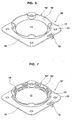
- FIGS. 6 and 7 are perspective views illustrating preferred embodiments of the retainer ring having an air deflector according to the present invention.
-
- Referring to FIGS. 2 through 5, an airbag mounting structure is largely comprised of a
retainer ring 10, anairbag 20, abaseplate 30, and aninflater 40. Theairbag 20 is mounted to thebaseplate 30 and a substantially squarelower flange 41 integrally formed with theinflater 40, using theretainer ring 10 and ordinary coupling means such as a bolt-and-nut configuration or rivets, such that amain body 44 of the inflater, where a plurality ofinflation ports 47 are located, protrudes into the airbag's interior throughcircular inflater openings coupling holes lower flange 41. - The
retainer ring 10 largely comprises anupper flange 16, having the inflater opening 11 formed therein, and anair deflector 14. Theair deflector 14 is comprised of awall 15, whose base is connected to theupper flange 16 and which extends upward and outward from the inflater opening 11 at a predetermined angle of 115∼120°, so that the wall's distal end forms a round opening greater in diameter than that of the inflater openings. It is preferable that, after assembly, the top of thewall 15 is level with or higher than the top of themain body 44 of theinflater 40. Theupper flange 16 is substantially rectangular in shape and has a tabbed cut-out 12 juxtaposed to-one of thecoupling holes 13, which is U-shaped and bent downward at a right angle to determine mounting position and orientation by alignment during assembly withcorresponding alignment holes airbag 20,baseplate 30, andinflater 40, respectively. Thealignment hole 42 is preferably a slotted notch to facilitate assembly, and the tabbed cut-out 12 may be of a squared shape. - The
airbag 20 comprises a mounting surface 20a acting as a collar extending from the inflater opening 23 to have a predetermined width extending beyond that of theupper flange 16, to which a tether (not shown) may be coupled. The mounting surface 20a may include a heat-resistant coating layer (not shown) of insulating or fire-proof material formed on the top and bottom sides thereof. - The
baseplate 30 is mounted to a point on the automobile, such as a support of the steering wheel, as shown in FIG. 2. - The plurality of
inflation ports 47 are evenly spaced around the circumference of theupper portion 44 of theinflater 40, to ensure that proper inflation of theairbag 20 is achieved. - Referring to FIG. 6, a retainer ring 10' includes an air deflector 14' according to a preferred embodiment of the present invention. The air deflector 14' is provided with a wall 15' comprising a plurality of semi-circular
convex portions 17 projecting inwardly towards the perimeter of theinflater opening 11, which are regularly spaced to provide support to theinflater 40 at the sides of themain body 44 thereof, when the inflater is inserted through theinflater openings convex portions 17 are formed around the circumference of the wall 15' at positions corresponding to the coupling holes 13 and do not coincide with theinflation ports 47. - Referring to FIG. 7, a
retainer ring 10" includes anair deflector 14" according to another preferred embodiment of the present invention. Theair deflector 14" is provided with awall 15" further comprising a plurality ofrib formations 18 integrally formed on the inner side of the wall in a discontinuous manner interrupted by theconvex portions 17, thus corresponding to the location of theinflation ports 47 and blocking a downward flow of hot air expelled therefrom, to thereby prevent the burning of an unprotected portion (between the mounting surfaces 20a) of the throat of theairbag 20 while diffusing and deflecting the gas upward. Therib formations 18 slope downward on either side of theconvex portions 17. Therib formations 18 are preferably evenly spaced as a pair of rows covering the height of the inner side of thewall 15". - Accordingly, the above-described simplified configuration of the retainer ring having an air deflector, comprising the wall, the convex portions, and the rib formations, blocks the downward discharge of hot inflation gas, to prevent the throat of the airbag from being burned thereby.
- Since the present invention may be embodied in various forms, without departing from the essential characteristics thereof, it should be understood that the above-described embodiment is not to be limited by any of the details of the foregoing description, unless otherwise specified, but should be construed only as defined in the appended claims. Thus, all modifications that fall within the scope of the claims are therefore intended to be embraced thereby.
Claims (20)
- A retainer ring having an air deflector, for use with an airbag mounting structure, said retainer ring comprising:an upper flange in which an inflater opening-for receiving an inflater is formed; anda wall, a base of which is connected to the upper flange, extending upward and outward from the inflater opening at a predetermined angle to diffuse and deflect exploding gas upward.
- The retainer ring as claimed in claim 1, wherein a distal end of said wall forms a round opening larger than the inflater opening.
- The retainer ring as claimed in claim 1, wherein the predetermined angle is between 115° and 120°.
- The retainer ring as claimed in claim 1, wherein said upper flange is substantially rectangular in shape and-has a coupling hole formed in each corner.
- The retainer ring as claimed in claim 4, wherein a tabbed cut-out is formed in said upper flange, juxtaposed to one of the coupling holes, the tabbed cut-out being bent downward at a right angle.
- The retainer ring as claimed in claim 5, wherein the tabbed cut-out is U-shaped.
- The retainer ring as claimed in claim 1, wherein said wall comprises a plurality of convex portions projecting inwardly towards the inflater opening, said plurality of convex portions being regularly spaced.
- The retainer ring as claimed in claim 7, wherein said plurality of convex portions are semi-circular in shape.
- The retainer ring as claimed in claim 7, wherein said wall further comprises a plurality of rib formations integrally formed on an inner side of said wall between said convex portions.
- The retainer ring as claimed in claim 9, wherein said plurality of rib formations slope downward on either side of said plurality of convex portions.
- The retainer ring as claimed in claim 9, wherein said plurality of rib formations are evenly spaced as a pair of rows covering the height of the inner side of said wall.
- An airbag mounting structure comprising:an inflater including a plurality of inflation ports provided on a main body thereof and arranged around the circumference of the main body, and a lower flange in which a plurality of first coupling holes and an alignment notch are formed at predetermined positions;a baseplate in which a first circular opening is formed to seat the main body of said inflater, a plurality of second coupling holes and a first alignment hole, corresponding to the first coupling holes, being formed in said baseplate around the first circular opening;an airbag, in which a second circular opening is formed to receive the main body of said inflater, having a mounting surface provided around the second circular opening, in which a plurality of third coupling holes and a second alignment hole, corresponding to the first and second coupling holes and the first alignment hole, respectively, are formed; anda retainer ring in which a third circular opening is formed to receive the main body of said inflater, a plurality of fourth coupling holes and a third alignment hole being formed in an upper flange to correspond to the first, second, and third coupling holes and the first and second alignment holes, respectively, said retainer ring including an integrally formed air deflector and a tabbed cut-out juxtaposed to one of the fourth coupling holes, the tabbed cut-out being bent at a right angle,wherein the tabbed cut-out passes through the alignment notch and the first, second, and third alignment holes during assembly, to determine a mounting position and orientation.
- The airbag mounting structure as claimed in claim 12, wherein said airbag further comprises a tethered collar provided with a heat-resistant coating layer extending beyond the upper flange of said retainer ring, to mate with mounting surfaces of said retainer ring and said baseplate.
- The airbag mounting structure as claimed in claim 13, wherein said retainer ring further comprises a wall, a base of which is connected to the upper flange, extending upward and outward from the inflater opening at a predetermined angle to diffuse and deflect exploding gas upward.
- The airbag mounting structure as claimed in claim 14, wherein the height of said wall is greater than or equal to a protruding height of said inflater, when said inflater is seated with said baseplate.
- The airbag mounting structure as claimed in claim 14, further comprising a plurality of convex portions projecting inwardly towards the inflater opening, said plurality of convex portions being regularly spaced around the circumference of said wall at positions corresponding to the first through fourth coupling holes and abutting a surface of the main body of said inflater when said inflater is seated with said baseplate, to support the main body of said inflater.
- The retainer ring as claimed in claim 16, wherein said plurality of convex portions are semi-circular in shape.
- The retainer ring as claimed in claim 16, wherein said wall further comprises a plurality of rib formations integrally formed on an inner side of said wall between said convex portions.
- The retainer ring as claimed in claim 18, wherein said plurality of rib formations slope downward on either side of said plurality of convex portions.
- The retainer ring as claimed in claim 18, wherein said plurality of rib formations are evenly spaced as a pair of rows covering the height of the inner side of said wall.
Priority Applications (3)
| Application Number | Priority Date | Filing Date | Title |
|---|---|---|---|
| US09/478,178 US6364342B1 (en) | 2000-01-05 | 2000-01-05 | Retainer ring having air deflector and airbag mounting structure using the same |
| EP00300028A EP1114758B1 (en) | 2000-01-05 | 2000-01-05 | Airbag mounting structure with air deflector |
| DE2000607268 DE60007268T2 (en) | 2000-01-05 | 2000-01-05 | Airbag assembly structure with air baffle |
Applications Claiming Priority (2)
| Application Number | Priority Date | Filing Date | Title |
|---|---|---|---|
| US09/478,178 US6364342B1 (en) | 2000-01-05 | 2000-01-05 | Retainer ring having air deflector and airbag mounting structure using the same |
| EP00300028A EP1114758B1 (en) | 2000-01-05 | 2000-01-05 | Airbag mounting structure with air deflector |
Publications (2)
| Publication Number | Publication Date |
|---|---|
| EP1114758A1 true EP1114758A1 (en) | 2001-07-11 |
| EP1114758B1 EP1114758B1 (en) | 2003-12-17 |
Family
ID=26072955
Family Applications (1)
| Application Number | Title | Priority Date | Filing Date |
|---|---|---|---|
| EP00300028A Expired - Lifetime EP1114758B1 (en) | 2000-01-05 | 2000-01-05 | Airbag mounting structure with air deflector |
Country Status (2)
| Country | Link |
|---|---|
| US (1) | US6364342B1 (en) |
| EP (1) | EP1114758B1 (en) |
Cited By (1)
| Publication number | Priority date | Publication date | Assignee | Title |
|---|---|---|---|---|
| WO2012095137A1 (en) * | 2011-01-12 | 2012-07-19 | Daimler Ag | Airbag, in particular for a motor vehicle |
Families Citing this family (22)
| Publication number | Priority date | Publication date | Assignee | Title |
|---|---|---|---|---|
| US6702318B2 (en) * | 2001-04-11 | 2004-03-09 | Autoliv Asp, Inc. | Vehicle occupant restraint module with disk inflator |
| US7150470B2 (en) * | 2002-05-31 | 2006-12-19 | Toyoda Gosei Co., Ltd. | Airbag device for front passenger's seat |
| US20040239080A1 (en) * | 2003-05-30 | 2004-12-02 | Berrahou Philip F. | Housing retention mechanism |
| DE10361887A1 (en) * | 2003-12-19 | 2005-07-14 | Takata-Petri Ag | Airbag device for a motor vehicle |
| DE102004040235A1 (en) * | 2004-08-13 | 2006-03-02 | Takata-Petri Ag | Passenger airbag module |
| EP2001423B1 (en) * | 2006-02-27 | 2010-10-06 | Alcon, Inc. | Computer program and system for a procedure based graphical interface |
| US9579429B2 (en) * | 2006-03-29 | 2017-02-28 | Novartis Ag | Surgical cassette with compliant clamping zone |
| US20070231205A1 (en) * | 2006-03-31 | 2007-10-04 | David Lloyd Williams | FlUIDIC CASSETTE DETECTION MECHANISM |
| US20070253850A1 (en) * | 2006-03-31 | 2007-11-01 | David Williams | System and method for user selectable release modality for a surgical cassette |
| US7712802B2 (en) * | 2006-06-12 | 2010-05-11 | Alcon, Inc. | Cassette clamping mechanism |
| US7786457B2 (en) * | 2006-06-28 | 2010-08-31 | Alcon, Inc. | Systems and methods of non-invasive level sensing for a surgical cassette |
| US20080003555A1 (en) * | 2006-06-29 | 2008-01-03 | Johan Ekvall | System and method for facilitating setup of surgical instrumentation and consumables associated therewith |
| US20080015515A1 (en) * | 2006-06-29 | 2008-01-17 | Mark Alan Hopkins | Top and bottom clamping for a surgical cassette |
| US8272387B2 (en) * | 2006-06-30 | 2012-09-25 | Novartis Ag | System and method for the modification of surgical procedures using a graphical drag and drop interface |
| US7764370B2 (en) * | 2006-06-30 | 2010-07-27 | Alcon, Inc. | System and method to zero chambers in a surgical cassette |
| US20090049397A1 (en) * | 2007-08-15 | 2009-02-19 | Mikhail Boukhny | System And Method For A Simple Graphical Interface |
| US20090171328A1 (en) * | 2007-12-27 | 2009-07-02 | Christopher Horvath | Surgical Console Display Operable to Provide a Visual Indication of a Status of a Surgical Laser |
| CN103465864B (en) * | 2008-09-30 | 2017-03-15 | Trw空气气袋系统股份有限公司 | Gas generator, its manufacture method and the module with gas generator |
| US7926837B2 (en) * | 2009-02-03 | 2011-04-19 | Trw Vehicle Safety Systems Inc. | Inflatable vehicle occupant protection device with inflation fluid deflector |
| US8760637B2 (en) | 2010-08-30 | 2014-06-24 | Alcon Research, Ltd. | Optical sensing system including electronically switched optical magnification |
| US11560113B2 (en) * | 2021-01-06 | 2023-01-24 | ZF Passive Safety Systems US Inc. | Airbag module with airbag retainer filter layer |
| KR20240111038A (en) * | 2023-01-09 | 2024-07-16 | 현대모비스 주식회사 | Retainer for airbag and retainer assembly for airbag comprising the same |
Citations (5)
| Publication number | Priority date | Publication date | Assignee | Title |
|---|---|---|---|---|
| DE3604843A1 (en) * | 1986-02-15 | 1987-08-27 | Daimler Benz Ag | Gas generator |
| EP0469734A1 (en) * | 1990-07-30 | 1992-02-05 | Takata Inc. | Air cushion restraint device having reinforced inflation attachment |
| US5501484A (en) * | 1995-03-20 | 1996-03-26 | Morton International, Inc. | Rivetless cushion retaining ring with tabs which lock the ring in place after rotation |
| EP0844149A1 (en) * | 1996-11-25 | 1998-05-27 | Autoliv ASP, Inc. | Airbag baffle mount |
| US5836608A (en) * | 1996-12-11 | 1998-11-17 | Morton International, Inc. | Airbag deflection mount |
Family Cites Families (10)
| Publication number | Priority date | Publication date | Assignee | Title |
|---|---|---|---|---|
| US5368327A (en) | 1989-07-12 | 1994-11-29 | Toyoda Gosei, Co., Ltd. | Air bag device |
| US5022676A (en) * | 1990-01-25 | 1991-06-11 | Allied-Signal Inc. | Air bag assembly and method therefor |
| US5388858A (en) * | 1991-02-25 | 1995-02-14 | Trw, Inc. | Air bag module structure and method of assembly |
| US5277442A (en) * | 1992-02-14 | 1994-01-11 | Trw Inc. | Driver side inflatable air bag system and method of assembly |
| JP3015655B2 (en) * | 1994-03-15 | 2000-03-06 | 株式会社東海理化電機製作所 | Airbag device |
| US5658008A (en) * | 1994-07-19 | 1997-08-19 | Takata (Europe) Vehicle Safety Technology Gmbh | Airbag arrangement |
| US5542692A (en) * | 1994-10-18 | 1996-08-06 | Morton International, Inc. | Inflatable cushion assembly and system |
| US5615907A (en) * | 1996-06-25 | 1997-04-01 | Morton International, Inc. | Airbag inflator retention tabs |
| US5683100A (en) * | 1996-07-12 | 1997-11-04 | Morton International, Inc. | Airbag cushion retainer with annular sewing area |
| US6017054A (en) * | 1997-10-07 | 2000-01-25 | Trw Inc. | Vehicle occupant protection apparatus |
-
2000
- 2000-01-05 US US09/478,178 patent/US6364342B1/en not_active Expired - Lifetime
- 2000-01-05 EP EP00300028A patent/EP1114758B1/en not_active Expired - Lifetime
Patent Citations (5)
| Publication number | Priority date | Publication date | Assignee | Title |
|---|---|---|---|---|
| DE3604843A1 (en) * | 1986-02-15 | 1987-08-27 | Daimler Benz Ag | Gas generator |
| EP0469734A1 (en) * | 1990-07-30 | 1992-02-05 | Takata Inc. | Air cushion restraint device having reinforced inflation attachment |
| US5501484A (en) * | 1995-03-20 | 1996-03-26 | Morton International, Inc. | Rivetless cushion retaining ring with tabs which lock the ring in place after rotation |
| EP0844149A1 (en) * | 1996-11-25 | 1998-05-27 | Autoliv ASP, Inc. | Airbag baffle mount |
| US5836608A (en) * | 1996-12-11 | 1998-11-17 | Morton International, Inc. | Airbag deflection mount |
Cited By (1)
| Publication number | Priority date | Publication date | Assignee | Title |
|---|---|---|---|---|
| WO2012095137A1 (en) * | 2011-01-12 | 2012-07-19 | Daimler Ag | Airbag, in particular for a motor vehicle |
Also Published As
| Publication number | Publication date |
|---|---|
| US6364342B1 (en) | 2002-04-02 |
| EP1114758B1 (en) | 2003-12-17 |
Similar Documents
| Publication | Publication Date | Title |
|---|---|---|
| EP1114758B1 (en) | Airbag mounting structure with air deflector | |
| JP2603793B2 (en) | Airbag assembly | |
| US6702318B2 (en) | Vehicle occupant restraint module with disk inflator | |
| US6231068B1 (en) | Seat mounted air bag module | |
| US6976700B2 (en) | Air bag inflator bracket | |
| KR100341271B1 (en) | Air bag module with variable inflation | |
| EP0648167B1 (en) | Inflator mounting system | |
| US9387822B2 (en) | Airbag device | |
| JP3049669U (en) | Airbag deflection fittings | |
| US6419261B1 (en) | Airbag apparatus | |
| JPH05155300A (en) | Air bag | |
| JP3047916U (en) | Airbag device, airbag inflator assembly, and holding device for holding both inflator and cushion | |
| US6361064B1 (en) | Inflator seal retainer for an air bag module | |
| US6206417B1 (en) | Air bag inflator exit gas dispersion features | |
| US5788266A (en) | Simplified airbag module housing | |
| US5540460A (en) | Air bag module | |
| EP0663325B1 (en) | Passenger side airbag module having lengthened reaction canister | |
| US7121576B2 (en) | Airbag retention collar for airbag module assembly | |
| JP2022545902A (en) | Deflector for diffuser of gas generator, diffuser-deflector assembly group including such deflector, gas generator including such diffuser-deflector assembly group, method of manufacture and method of implementation | |
| JPH08230600A (en) | Air bag module | |
| JPH08230605A (en) | Car safety device | |
| US6217067B1 (en) | Flame protection for a gas bag | |
| US6547272B1 (en) | Air bag module with cover and reaction structure for withstanding lateral force of bag inflation | |
| EP1651472B1 (en) | An air-bag | |
| US5803488A (en) | Inflator retainer and air bag module |
Legal Events
| Date | Code | Title | Description |
|---|---|---|---|
| PUAI | Public reference made under article 153(3) epc to a published international application that has entered the european phase |
Free format text: ORIGINAL CODE: 0009012 |
|
| AK | Designated contracting states |
Kind code of ref document: A1 Designated state(s): DE FR GB IT |
|
| AX | Request for extension of the european patent |
Free format text: AL;LT;LV;MK;RO;SI |
|
| 17P | Request for examination filed |
Effective date: 20020110 |
|
| AKX | Designation fees paid |
Free format text: DE FR GB IT |
|
| RTI1 | Title (correction) |
Free format text: AIRBAG MOUNTING STRUCTURE WITH AIR DEFLECTOR |
|
| GRAH | Despatch of communication of intention to grant a patent |
Free format text: ORIGINAL CODE: EPIDOS IGRA |
|
| GRAS | Grant fee paid |
Free format text: ORIGINAL CODE: EPIDOSNIGR3 |
|
| GRAA | (expected) grant |
Free format text: ORIGINAL CODE: 0009210 |
|
| AK | Designated contracting states |
Kind code of ref document: B1 Designated state(s): DE FR GB IT |
|
| REG | Reference to a national code |
Ref country code: GB Ref legal event code: FG4D |
|
| REF | Corresponds to: |
Ref document number: 60007268 Country of ref document: DE Date of ref document: 20040129 Kind code of ref document: P |
|
| ET | Fr: translation filed | ||
| PLBE | No opposition filed within time limit |
Free format text: ORIGINAL CODE: 0009261 |
|
| STAA | Information on the status of an ep patent application or granted ep patent |
Free format text: STATUS: NO OPPOSITION FILED WITHIN TIME LIMIT |
|
| 26N | No opposition filed |
Effective date: 20040920 |
|
| REG | Reference to a national code |
Ref country code: FR Ref legal event code: CD |
|
| REG | Reference to a national code |
Ref country code: FR Ref legal event code: RERR Free format text: CORRECTION DE BOPI 07/33 - CHANGEMENT DE NOM, DE DENOMINATION. IL Y A LIEU DE SUPPRIMER : L INSCRIPTION N159683 DU 12/07/07 CONCERNANT UN CHANGEMENT DE NOM OU DE DENOMINATION |
|
| PG25 | Lapsed in a contracting state [announced via postgrant information from national office to epo] |
Ref country code: IT Free format text: LAPSE BECAUSE OF NON-PAYMENT OF DUE FEES Effective date: 20080105 |
|
| REG | Reference to a national code |
Ref country code: FR Ref legal event code: CD Ref country code: FR Ref legal event code: CJ |
|
| PGFP | Annual fee paid to national office [announced via postgrant information from national office to epo] |
Ref country code: FR Payment date: 20101125 Year of fee payment: 12 |
|
| PGFP | Annual fee paid to national office [announced via postgrant information from national office to epo] |
Ref country code: GB Payment date: 20101112 Year of fee payment: 12 |
|
| PGFP | Annual fee paid to national office [announced via postgrant information from national office to epo] |
Ref country code: IT Payment date: 20100115 Year of fee payment: 11 |
|
| PGRI | Patent reinstated in contracting state [announced from national office to epo] |
Ref country code: IT Effective date: 20110616 |
|
| PGRI | Patent reinstated in contracting state [announced from national office to epo] |
Ref country code: IT Effective date: 20110616 |
|
| GBPC | Gb: european patent ceased through non-payment of renewal fee |
Effective date: 20120105 |
|
| REG | Reference to a national code |
Ref country code: FR Ref legal event code: ST Effective date: 20120928 |
|
| PG25 | Lapsed in a contracting state [announced via postgrant information from national office to epo] |
Ref country code: GB Free format text: LAPSE BECAUSE OF NON-PAYMENT OF DUE FEES Effective date: 20120105 |
|
| PG25 | Lapsed in a contracting state [announced via postgrant information from national office to epo] |
Ref country code: FR Free format text: LAPSE BECAUSE OF NON-PAYMENT OF DUE FEES Effective date: 20120131 |
|
| PGFP | Annual fee paid to national office [announced via postgrant information from national office to epo] |
Ref country code: DE Payment date: 20180125 Year of fee payment: 19 |
|
| REG | Reference to a national code |
Ref country code: DE Ref legal event code: R119 Ref document number: 60007268 Country of ref document: DE |
|
| PG25 | Lapsed in a contracting state [announced via postgrant information from national office to epo] |
Ref country code: DE Free format text: LAPSE BECAUSE OF NON-PAYMENT OF DUE FEES Effective date: 20190801 |