EP1113700A2 - Speaker system - Google Patents
Speaker system Download PDFInfo
- Publication number
- EP1113700A2 EP1113700A2 EP00403648A EP00403648A EP1113700A2 EP 1113700 A2 EP1113700 A2 EP 1113700A2 EP 00403648 A EP00403648 A EP 00403648A EP 00403648 A EP00403648 A EP 00403648A EP 1113700 A2 EP1113700 A2 EP 1113700A2
- Authority
- EP
- European Patent Office
- Prior art keywords
- speaker
- duct
- bass reflex
- speaker system
- reflex duct
- Prior art date
- Legal status (The legal status is an assumption and is not a legal conclusion. Google has not performed a legal analysis and makes no representation as to the accuracy of the status listed.)
- Withdrawn
Links
Images


Classifications
-
- H—ELECTRICITY
- H04—ELECTRIC COMMUNICATION TECHNIQUE
- H04R—LOUDSPEAKERS, MICROPHONES, GRAMOPHONE PICK-UPS OR LIKE ACOUSTIC ELECTROMECHANICAL TRANSDUCERS; ELECTRIC HEARING AIDS; PUBLIC ADDRESS SYSTEMS
- H04R1/00—Details of transducers, loudspeakers or microphones
- H04R1/20—Arrangements for obtaining desired frequency or directional characteristics
- H04R1/22—Arrangements for obtaining desired frequency or directional characteristics for obtaining desired frequency characteristic only
- H04R1/28—Transducer mountings or enclosures modified by provision of mechanical or acoustic impedances, e.g. resonator, damping means
- H04R1/2807—Enclosures comprising vibrating or resonating arrangements
- H04R1/2815—Enclosures comprising vibrating or resonating arrangements of the bass reflex type
- H04R1/2819—Enclosures comprising vibrating or resonating arrangements of the bass reflex type for loudspeaker transducers
-
- H—ELECTRICITY
- H04—ELECTRIC COMMUNICATION TECHNIQUE
- H04R—LOUDSPEAKERS, MICROPHONES, GRAMOPHONE PICK-UPS OR LIKE ACOUSTIC ELECTROMECHANICAL TRANSDUCERS; ELECTRIC HEARING AIDS; PUBLIC ADDRESS SYSTEMS
- H04R1/00—Details of transducers, loudspeakers or microphones
- H04R1/20—Arrangements for obtaining desired frequency or directional characteristics
- H04R1/22—Arrangements for obtaining desired frequency or directional characteristics for obtaining desired frequency characteristic only
- H04R1/28—Transducer mountings or enclosures modified by provision of mechanical or acoustic impedances, e.g. resonator, damping means
- H04R1/2807—Enclosures comprising vibrating or resonating arrangements
- H04R1/2815—Enclosures comprising vibrating or resonating arrangements of the bass reflex type
- H04R1/2823—Vents, i.e. ports, e.g. shape thereof or tuning thereof with damping material
- H04R1/2826—Vents, i.e. ports, e.g. shape thereof or tuning thereof with damping material for loudspeaker transducers
Definitions
- the present invention relates to a speaker system, and more specifically, relates to a speaker system having a bass reflex duct to amplify a bass range.
- a bass reflex duct is located at the rear of the speaker inside of the speaker box.
- the bass reflex duct leads to a bass reflex port opened in the speaker box.
- the resonance frequency is determined by the interior volume of the speaker box, and by the diameter and the length of the bass reflex duct according to the Helmholtz resonance phenomenon. Therefore, in order to amplify the bass range, the sound of the desired frequency can be amplified by regulating the dimensions and arrangement of the speaker box and the bass reflex duct.
- the resonance frequency can thus be determined by making use of the Helmholtz resonance phenomenon.
- the diameter of the bass reflex duct is increased and the length of the bass reflex duct is increased, the size of the speaker box itself is increased.
- a compact speaker box is used, only a short bass reflex duct is possible.
- the diameter of the bass reflex port is of course decreased, and an increase in the sound pressure in the resonance cannot be expected.
- preferred embodiments of the present invention provide a speaker system that efficiently directs the back pressure of the speaker to the bass reflex duct to greatly increase the sound pressure in the resonance while greatly miniaturizing the dimensions of the speaker box.
- a speaker system includes a speaker box, a speaker mounted on the speaker box, a bass reflex duct located at the rear of the speaker in the speaker box, and an additional duct that is larger than the bass reflex duct and is disposed around the speaker inside the speaker box, wherein the bass reflex duct is arranged inside the additional duct, and the bass reflex duct and the additional duct overlap each other.
- the additional duct preferably has a substantially cylindrical shape.
- the bass reflex duct and the additional duct overlap each other, directionality is provided to the air flowing from the rear of the speaker into the speaker box and the back pressure of the speaker is easily and accurately directed to the bass reflex duct. Most of the back pressure of the speaker is directed and transmitted to the bass reflex duct, and the sound pressure at the resonance frequency is thereby greatly increased.
- the air resistance is substantially equal in all directions around the speaker when the back pressure of the speaker propagates inside the speaker box, the leakage of the back pressure is minimized, and most of the back pressure is directed to the bass reflex duct.
- the back pressure of the speaker is accurately and efficiently directed to the bass reflex duct, and the bass range is greatly amplified irrespective of the size and the shape of the speaker box.
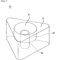
- FIG. 1 is a perspective view showing a preferred embodiment of a speaker system of the present invention
- Fig. 2 is a perspective view of this preferred embodiment viewed from the opposite side (underneath).
- a speaker system 10 according to this preferred embodiment is compact and includes, for example, a substantially equilaterally triangular prismatic speaker box 12.
- a speaker 14 is mounted at one substantially triangular surface of the speaker box 12.
- the speaker 14 is, for example, a piezoelectric type, a dynamic type, or, an electrostatic capacitor type.
- a substantially cylindrical bass reflex duct 16 is disposed at a rear surface of the speaker 14.
- the bass reflex duct 16 is arranged at a position corresponding to an approximate center portion of the rear surface of the speaker 14 but spaced from the speaker 14 and arranged to lead to a bass reflex port 18 penetrating the other substantially triangular surface of the speaker box 12.
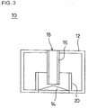
- an additional substantially cylindrical duct 20 is disposed around the speaker 14 inside of the speaker box 12. As illustrated in Fig. 3, the diameter of the duct 20 is preferably larger than the diameter of the bass reflex duct 16.
- the bass reflex duct 16 is disposed inside of the duct 20.
- the bass reflex duct 16 and the duct 20 overlap each other.
- the bass range is amplified by the bass reflex duct 16 and the bass reflex port 18.
- the frequency in the sound frequency range to be amplified is the resonance frequency determined by the interior volume of the speaker box 12, the length of the bass reflex duct 16, and the diameter of the bass reflex duct 16.
- Fig. 4 shows that the sound pressure level in the sound frequency range of about 60 Hz to about 100 Hz is high in both respective speaker systems. This shows that resonance occurs at a resonance frequency determined by the speaker box 12, the bass reflex duct 16, etc. Comparison of these speaker systems shows that the sound pressure level at the resonance frequency is substantially higher in the speaker system 10 having the duct 20.
- the resonance frequency is mainly determined by the interior volume of the speaker box 12 and the size of the bass reflex duct 16, a clearance is necessary between the bass reflex duct 16 and the duct 20, and between the duct 20 and an inner surface of the speaker box 12. This is because the interior volume relating to the resonance is the volume of a space to be defined by the bass reflex duct 16 and the duct 20 if there is no clearance therebetween, and the desired resonance frequency cannot be obtained.
- Such a structure is particularly effective for the compact speaker system 10.
- the short bass reflex duct 16 is preferably adopted in the compact speaker system 10, and the diameter of the bass reflex duct 16 is also decreased in accordance therewith.
- the back pressure of the speaker 14 is easily and efficiently led to the bass reflex duct 16 by the duct 20.
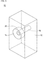
- the substantially equilaterally triangular prismatic speaker box 12 is included in the speaker system 10 shown in Fig. 1, and, of course, the sound pressure in the bass range is greatly amplified by providing the bass reflex duct 16 and another duct 20 also in a speaker system using a substantially rectangular prismatic speaker box 12 as illustrated in Fig. 5. Shapes other than the equilaterally prismatic or quadratic prismatic shape may be adopted as the shape of the speaker box 12.
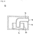
- the bass reflex duct 16 may be substantially straight, and substantially curved as shown in Fig. 6, or may have another suitable arrangement. Even when such a bass reflex duct 16 is adopted, the sound pressure in the bass range can be amplified by overlapping the bass reflex duct 16 and the duct 20 with each other.
- the bass reflex port 18 may be provided at the back or at the side of the speaker 14, or at the surface on which the speaker 14 is provided.
- the most preferable position of the bass reflex duct 16 is the position corresponding to an approximate center portion of the speaker 14, but the advantages of the present invention can be obtained as long as the bass reflex duct is disposed inside of the duct 20.
- the duct 20 may be substantially cylindrical and may also have a polygonal prismatic shape or other suitable shape. This means that the advantages of the present invention can be obtained if the air resistance from the speaker 14 to its periphery increases. However, in a duct having a polygonal prismatic shape, the difference in air resistance cannot be avoided due to the difference in distance from the speaker 14 to the duct 20. Thus, the substantially cylindrical shape is most preferable for the duct 20.
Landscapes
- Health & Medical Sciences (AREA)
- Otolaryngology (AREA)
- Physics & Mathematics (AREA)
- Engineering & Computer Science (AREA)
- Acoustics & Sound (AREA)
- Signal Processing (AREA)
- Details Of Audible-Bandwidth Transducers (AREA)
- Obtaining Desirable Characteristics In Audible-Bandwidth Transducers (AREA)
Abstract
Description
Claims (13)
- A speaker system (10) comprising:a speaker box (12);a speaker (14) mounted on said speaker box;a bass reflex duct (16) disposed at a rear portion of said speaker in said speaker box; andanother duct (20) that is larger than said bass reflex duct and is disposed around said speaker (14) inside of said speaker box (12); whereinsaid bass reflex duct (16) is arranged inside of said another duct (20), and said bass reflex duct and said another duct overlap each other.
- A speaker system according to claim 1, wherein said another duct (20) has a substantially cylindrical shape.
- A speaker system according to claim 1 or 2, wherein said speaker box (12) has a substantially equilaterally triangular prismatic configuration.
- A speaker system according to claim 1, 2 or 3, wherein the speaker (14) is one of a piezoelectric type, a dynamic type, and an electrostatic capacitor type.
- A speaker system according to any previous claim, wherein said bass reflex duct (16) has a substantially cylindrical shape.
- A speaker system according to any previous claim, wherein said bass reflex duct (16) is disposed at an approximate center portion of the rear surface of said speaker (14).
- A speaker system according to any previous claim, wherein said bass reflex duct (16) is spaced from said speaker (14).
- A speaker system according to any previous claim, further comprising a bass reflex port (18) arranged to penetrate a surface of the speaker box (12), wherein said bass reflex duct (16) is arranged to lead to the bass reflex port (18).
- A speaker system according to any previous claim, wherein the bass reflex duct (16) and the additional duct (20) are arranged to direct the back pressure from the speaker (14) to the bass reflect duct.
- A speaker system according to any previous claim, wherein a clearance is provided between the bass reflex duct (16) and the additional duct (20).
- A speaker system according to any previous claim, wherein a clearance is provided between additional duct (20) and the speaker box (12).
- A speaker system according to any previous claim, wherein the bass reflex duct (16) has one of a substantially straight configuration and a substantially curved configuration.
- A speaker system according to any previous claim, wherein said additional duct (20) has a diameter that is larger than that of said bass reflex duct (16).
Applications Claiming Priority (2)
| Application Number | Priority Date | Filing Date | Title |
|---|---|---|---|
| JP37438099A JP3521825B2 (en) | 1999-12-28 | 1999-12-28 | Speaker system |
| JP37438099 | 1999-12-28 |
Publications (2)
| Publication Number | Publication Date |
|---|---|
| EP1113700A2 true EP1113700A2 (en) | 2001-07-04 |
| EP1113700A3 EP1113700A3 (en) | 2005-02-16 |
Family
ID=18503754
Family Applications (1)
| Application Number | Title | Priority Date | Filing Date |
|---|---|---|---|
| EP00403648A Withdrawn EP1113700A3 (en) | 1999-12-28 | 2000-12-21 | Speaker system |
Country Status (3)
| Country | Link |
|---|---|
| US (1) | US6618488B2 (en) |
| EP (1) | EP1113700A3 (en) |
| JP (1) | JP3521825B2 (en) |
Cited By (5)
| Publication number | Priority date | Publication date | Assignee | Title |
|---|---|---|---|---|
| GB2491283A (en) * | 2008-05-12 | 2012-11-28 | Intelliject Inc | Medicament delivery device having an electronic circuit system |
| US8622973B2 (en) | 2008-07-28 | 2014-01-07 | Intelliject, Inc. | Simulated medicament delivery device configured to produce an audible output |
| US8899987B2 (en) | 2005-02-01 | 2014-12-02 | Kaleo, Inc. | Simulated medicament delivery device having an electronic circuit system |
| US8932252B2 (en) | 2005-02-01 | 2015-01-13 | Kaleo, Inc. | Medical injector simulation device |
| USD994111S1 (en) | 2008-05-12 | 2023-08-01 | Kaleo, Inc. | Medicament delivery device cover |
Families Citing this family (12)
| Publication number | Priority date | Publication date | Assignee | Title |
|---|---|---|---|---|
| US10842677B2 (en) * | 1996-03-11 | 2020-11-24 | Horst Burghardt Minkofski | Sound baffling device and material |
| CN102036136A (en) * | 2009-09-29 | 2011-04-27 | 鸿富锦精密工业(深圳)有限公司 | Portable sound box |
| CN102209285A (en) * | 2010-03-31 | 2011-10-05 | 鸿富锦精密工业(深圳)有限公司 | Loudspeaker box |
| US9351059B1 (en) * | 2013-09-05 | 2016-05-24 | James R. Suhre | Orthogonal open back speaker system |
| JP6267172B2 (en) * | 2015-10-23 | 2018-01-24 | ファナック株式会社 | Injection molding system |
| JP6590637B2 (en) * | 2015-10-28 | 2019-10-16 | Dmg森精機株式会社 | Speaker device |
| CN107018459B (en) * | 2016-01-27 | 2019-09-20 | 信泰光学(深圳)有限公司 | Earphone |
| CN107018458B (en) * | 2016-01-27 | 2020-02-21 | 信泰光学(深圳)有限公司 | Earphone set |
| USD843341S1 (en) * | 2016-08-31 | 2019-03-19 | Rembrandt Laboratories, Llc | Speaker cabinet |
| USD894865S1 (en) * | 2018-08-10 | 2020-09-01 | Alibaba Group Holding Limited | Combined payment device and speaker |
| USD920947S1 (en) * | 2019-07-19 | 2021-06-01 | Ifory Limited | Bluetooth speaker |
| USD928735S1 (en) * | 2019-08-23 | 2021-08-24 | Lg Electronics Inc. | Speaker |
Family Cites Families (5)
| Publication number | Priority date | Publication date | Assignee | Title |
|---|---|---|---|---|
| US4348552A (en) * | 1980-06-09 | 1982-09-07 | Siccone Ralph R | Direct/reflecting speaker system and triangular shaped enclosure |
| CH667174A5 (en) * | 1986-06-05 | 1988-09-15 | Sound Electronic Systems | MONOLITHIC STEREOPHONIC SPEAKER. |
| US5406637A (en) * | 1993-10-04 | 1995-04-11 | Gonzalez; Hector M. | Speaker enclosure assembly |
| US5623132A (en) * | 1995-08-18 | 1997-04-22 | Precision Sound Products, Inc. | Modular port tuning kit |
| US6144751A (en) * | 1998-02-24 | 2000-11-07 | Velandia; Erich M. | Concentrically aligned speaker enclosure |
-
1999
- 1999-12-28 JP JP37438099A patent/JP3521825B2/en not_active Expired - Fee Related
-
2000
- 2000-12-21 EP EP00403648A patent/EP1113700A3/en not_active Withdrawn
- 2000-12-28 US US09/749,975 patent/US6618488B2/en not_active Expired - Fee Related
Cited By (11)
| Publication number | Priority date | Publication date | Assignee | Title |
|---|---|---|---|---|
| US8899987B2 (en) | 2005-02-01 | 2014-12-02 | Kaleo, Inc. | Simulated medicament delivery device having an electronic circuit system |
| US8932252B2 (en) | 2005-02-01 | 2015-01-13 | Kaleo, Inc. | Medical injector simulation device |
| US9238108B2 (en) | 2005-02-01 | 2016-01-19 | Kaleo, Inc. | Medicament delivery device having an electronic circuit system |
| US10076611B2 (en) | 2005-02-01 | 2018-09-18 | Kaleo, Inc. | Medicament delivery device having an electronic circuit system |
| GB2491283A (en) * | 2008-05-12 | 2012-11-28 | Intelliject Inc | Medicament delivery device having an electronic circuit system |
| GB2491283B (en) * | 2008-05-12 | 2013-03-06 | Intelliject Inc | Medicament delivery device having an electronic circuit system |
| USD994111S1 (en) | 2008-05-12 | 2023-08-01 | Kaleo, Inc. | Medicament delivery device cover |
| USD1043972S1 (en) | 2008-05-12 | 2024-09-24 | Kaleo, Inc. | Medicament delivery device cover |
| US8622973B2 (en) | 2008-07-28 | 2014-01-07 | Intelliject, Inc. | Simulated medicament delivery device configured to produce an audible output |
| US10192464B2 (en) | 2008-07-28 | 2019-01-29 | Kaleo, Inc. | Medicament delivery device configured to produce wireless and audible outputs |
| US11263921B2 (en) | 2008-07-28 | 2022-03-01 | Kaleo, Inc. | Medicament delivery device configured to produce wireless and audible outputs |
Also Published As
| Publication number | Publication date |
|---|---|
| JP2001189984A (en) | 2001-07-10 |
| JP3521825B2 (en) | 2004-04-26 |
| EP1113700A3 (en) | 2005-02-16 |
| US20010005422A1 (en) | 2001-06-28 |
| US6618488B2 (en) | 2003-09-09 |
Similar Documents
| Publication | Publication Date | Title |
|---|---|---|
| US6618488B2 (en) | Speaker system | |
| US4756382A (en) | Loudspeaker having enhanced response at bass frequencies | |
| US6118883A (en) | System for controlling low frequency acoustical directivity patterns and minimizing directivity discontinuities during frequency transitions | |
| US5197103A (en) | Low sound loudspeaker system | |
| US5097513A (en) | Speaker system enclosure integrated with amplifier circuit board | |
| EP0915636A2 (en) | Radially expanding multiple flat surfaced waveguide device | |
| AU1082388A (en) | Sound reinforcement enclosure employing cone loudspeaker with annular central loading member and coaxially mounted compression driver | |
| WO2000067522A3 (en) | Reflexion-type loudspeaker system | |
| US11172276B2 (en) | Annular radiation speaker structure | |
| US6981570B2 (en) | Loudspeaker system with common low and high frequency horn mounting | |
| US11937046B2 (en) | Sound diffuser and diffusion method | |
| EP3346727A1 (en) | Speaker device | |
| JP5626096B2 (en) | Ceiling-mounted speaker system and lighting device using the same | |
| US6453049B1 (en) | Acoustic diaphragm | |
| US6661903B1 (en) | Loudspeaker | |
| KR102097891B1 (en) | Three-Dimensional Sound Guide for Speaker and Speaker Having the Same | |
| KR100383469B1 (en) | Device with loudspeaker unit and loudspeaker unit | |
| US6597795B1 (en) | Device to improve loudspeaker enclosure duct | |
| US12389147B2 (en) | Loudspeaker and housing configuration | |
| CN213126358U (en) | Horn, sound box and public address equipment | |
| US20070274554A1 (en) | Reversible speaker grill attachment | |
| JPH04287497A (en) | Speaker system | |
| JPH0998492A (en) | Box speaker | |
| JP3816016B2 (en) | Bass reflex type speaker device | |
| KR960043963A (en) | Speaker device |
Legal Events
| Date | Code | Title | Description |
|---|---|---|---|
| PUAI | Public reference made under article 153(3) epc to a published international application that has entered the european phase |
Free format text: ORIGINAL CODE: 0009012 |
|
| 17P | Request for examination filed |
Effective date: 20001228 |
|
| AK | Designated contracting states |
Kind code of ref document: A2 Designated state(s): AT BE CH CY DE DK ES FI FR GB GR IE IT LI LU MC NL PT SE TR |
|
| AX | Request for extension of the european patent |
Free format text: AL;LT;LV;MK;RO;SI |
|
| PUAL | Search report despatched |
Free format text: ORIGINAL CODE: 0009013 |
|
| AK | Designated contracting states |
Kind code of ref document: A3 Designated state(s): AT BE CH CY DE DK ES FI FR GB GR IE IT LI LU MC NL PT SE TR |
|
| AX | Request for extension of the european patent |
Extension state: AL LT LV MK RO SI |
|
| AKX | Designation fees paid |
Designated state(s): DE FR GB |
|
| STAA | Information on the status of an ep patent application or granted ep patent |
Free format text: STATUS: THE APPLICATION IS DEEMED TO BE WITHDRAWN |
|
| 18D | Application deemed to be withdrawn |
Effective date: 20060714 |