EP1113695A2 - Optical packet switching - Google Patents
Optical packet switching Download PDFInfo
- Publication number
- EP1113695A2 EP1113695A2 EP00309224A EP00309224A EP1113695A2 EP 1113695 A2 EP1113695 A2 EP 1113695A2 EP 00309224 A EP00309224 A EP 00309224A EP 00309224 A EP00309224 A EP 00309224A EP 1113695 A2 EP1113695 A2 EP 1113695A2
- Authority
- EP
- European Patent Office
- Prior art keywords
- data
- optical
- payload
- phase
- payload part
- Prior art date
- Legal status (The legal status is an assumption and is not a legal conclusion. Google has not performed a legal analysis and makes no representation as to the accuracy of the status listed.)
- Withdrawn
Links
Images


Classifications
-
- H—ELECTRICITY
- H04—ELECTRIC COMMUNICATION TECHNIQUE
- H04Q—SELECTING
- H04Q11/00—Selecting arrangements for multiplex systems
- H04Q11/0001—Selecting arrangements for multiplex systems using optical switching
- H04Q11/0005—Switch and router aspects
-
- H—ELECTRICITY
- H04—ELECTRIC COMMUNICATION TECHNIQUE
- H04Q—SELECTING
- H04Q11/00—Selecting arrangements for multiplex systems
- H04Q11/0001—Selecting arrangements for multiplex systems using optical switching
- H04Q11/0062—Network aspects
- H04Q11/0066—Provisions for optical burst or packet networks
-
- H—ELECTRICITY
- H04—ELECTRIC COMMUNICATION TECHNIQUE
- H04Q—SELECTING
- H04Q11/00—Selecting arrangements for multiplex systems
- H04Q11/0001—Selecting arrangements for multiplex systems using optical switching
- H04Q11/0005—Switch and router aspects
- H04Q2011/0037—Operation
- H04Q2011/0041—Optical control
Definitions
- This invention relates to the field of optical signal processing, and in particular to the processing of packet-based optical signals and to the reading and updating of the routing information and the like contained in such packets, typically in headers of such packets.
- SONET is one of the many physical layers defined for ATM, which is itself a cell-based (i.e. packet-based) switching and multiplexing technology.
- United States Patent 5,541,756 proposes the use of a packet header with wavelength-coded data, in conjunction with a grating operating as a wavelength differentiator. Different wavelength signals within the optical header are deflected by the grating by different amounts to be incident upon photo-electric sensors positioned at different locations.
- ASK amplitude shift keying
- the present invention is directed to the provision of a format of optical transmission network in which data packets, having a data-payload part and a non-payload that includes data packet routing information, can have their non-payload parts rewritten without having to have recourse to the use of an optical source at the location of such rewriting.
- an optical transmission network in which data packets, having a data-payload part and a non-payload that includes data packet routing information, are routed by an optical switch in different paths according to the routing information contained in the non-payload part of their respective data packets, and wherein the data-payload part of a data packet is transmitted as amplitude shift keying of an optical carrier while the non-payload part is transmitted as phase shift keying of the optical carrier.
- the non-payload parts of such data packets take the form of data packet headers. There is thus no intrinsic reason why the non-payload parts of such data packets should not take the form of data packet footers.
- a data packet indicated generally at 10 comprises an intensity modulated (ASK) data payload part 11, preceded by a differential phase shift keyed (DPSK) header 12 that contains routing information.
- ASK intensity modulated
- DPSK differential phase shift keyed
- FIG 2 schematically depicts a switch (router) employed in an optical transmission network using the data packets of Figure 1.
- a switch employed in an optical transmission network using the data packets of Figure 1.
- an optical tap 20 taps off a small proportion of the power of the received signal, and feeds the tapped power to a DPSK demodulator.
- this demodulator may comprise a Mach Zehnder interferometer, and this is followed by a differential optical detector to convert the demodulated optical header into an electrical analogue.
- the interferometer comprises a pair of 2 ⁇ 2 3dB optical waveguide couplers 21a and 21b defining between them a pair of interference arms 22, one of which incorporates a delay 23 of magnitude ⁇ 1 which is equal to one DPSK bit period.
- the differential detector comprises a pair of photodiodes 24 followed by an amplifier 24a.
- the output of amplifier 24a provides an input to a switch controller 25 that controls, via line 25a, the operation of an optical selector 26 directing an input to the selector 26 on line 27 0 to a selected one on its n output lines 27 1 , 27 2 , 27 3 , ...27 n .
- Optical line 27 0 receives its input from the non-tapped output of tap 20 via a delay unit 28 that affords a delay of magnitude ⁇ 2 sufficient to delay the arrival of each data packet 10 until after the selector 26 has had time to be set by the controller 25 in response to the detected signal it has received from the DPSK demodulator in respect of that data packet.
- a simple form of router having no facility for rewriting the DPSK headers 12 of data packets 10 may be modified to provide this facility by incorporating an active phase adjuster 29 with the passive delay unit 28.
- the total differential delay between the two interference arms 22 of the Mach Zehnder interferometer is such as to correspond to a phase difference substantially equal to 2N ⁇ or 2(n + 1) ⁇ , where N is an integer.
- N is an integer.
- Figure 3 depicts, as a function of time, the phase of an illustrative 12-bit DPSK header 12, while Figure 4 depicts the same header delayed by one DPSK bit period.
- Figure 5 depicts, as a function of time, the amplitude of the response of one of the photodetectors 24. (The amplitude of the response of the other photodetector; 24 is the inverse of the waveform of Figure 5.)
- Figure 6 depicts, as a function of time, an illustrative waveform applied over line 25b to control the operation of phase adjuster 29.
- the illustrative waveform of Figure 6 is such as to produce phase inversion in bit periods 3, 6, 7, 8 and 11, and so will operate con the original DPSK header of Figure 3, reproduced as Figure 7, to provide the new header of Figure 8.
- phase reference preamble can be a DPSK signal or a signal of known phase, for instance a signal whose phase is midway between the two phases of the ensuing DPSK header.
- active phase lock circuitry such as a fast phase modulator and fast phase locked loop (neither shown).
- a phase diversity receiver is like a simple Mach Zehnder interferometer receiver to the extent that both types of receiver rely upon employing interference effects to measure phase; the phase diversity receiver is distinguished from the simple Mach Zehnder interferometer receiver in that the former relies upon simultaneously employing two different interference conditions for its measurement so that, whenever either one of these interference conditions assumes a phase quadrature relationship, then for the whole time that that relationship is maintained, the other phase relationship is maintained in a phase relationship that is necessarily not a phase quadrature relationship.
- phase diversity receiver uses all the components of the Mach Zehnder interferometer and differential detector of Figure 2, and additionally includes three further 2 ⁇ 2 3dB optical waveguide couplers 90, 91 and 92, a delay 93, and a further differential detector comprised by a pair of photodiodes 94.
- the magnitude of the delay 93 is such as to introduce a phase quadrature condition between the way in which power from the two interference arms 22 is interfered in coupler 21b and in coupler 92.
- the difference in optical path length, if any, between coupler 21b and couplers 90 and 91 corresponds to a phase angle ⁇
- the corresponding difference in optical path length, if any, between coupler 91 and couplers 90 and 91 corresponds to a phase angle ( ⁇ + ⁇ /2).
- adjustment of the delay 93 to its required magnitude may conveniently be effected by irradiating a portion of one of the interference arms with a controlled amount of intense UV light.
- phase condition is such that coupler 21b divides the light equally between the two photodiodes 24 for a DPSK bit of one data significance, then it will similarly divide the light equally for a DPSK bit of the other data significance. Designating the output of the differential amplifier 24 as the I output, then, under these conditions the magnitude of the voltage swing, V I produced by DPSK data bit significance transitions from this output is zero.
- this phase condition is also such that coupler 91 will apply the light substantially exclusively to just one of its diodes 94 for a DPSK bit of one data significance, and substantially exclusively to the other of its diodes 94 for a DPSK bit of the data significance.
- a particular feature of using a DPSK header in conjunction with an ASK payload is that the DPSK format is readily distinguishable at a detector from the ASK format, and so neither part constrains the format of the other part..
- a long sequence of data '0's or data '1's if acceptable in the payload part of a data packet, can be tolerated by a detector of the headers of such packets.
- Such a sequence can be readily prevented from being spuriously interpreted at a detector of headers as part of a header by looking for zero-crossings.
- ASK data will produce modulation of the amplitudes of the outputs V I and V Q , but will never produce a zero-crossing.
- each data bit significance transition of a DPSK header produces a zero-crossing in either or both of the outputs V I and V Q .
- a simple zero-crossing detector for instance as schematically depicted in Figure 10, can tap a signal from the output V output to provide an output employed to gate V output so as to prevent it from reaching switch controller 25 except when DPSK signals (headers) are specifically detected as being present.
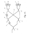
- Figure 11 depicts an alternative topology of phase diversity receiver, one whose configuration of waveguides can be implemented in a compact integrated waveguide (so-called planar waveguide) format by virtue of its inclusion of a 'level-crossing' type intersection 110 of waveguides.
- optical power launched into any one of its four component waveguides is coupled virtually exclusively into the opposite waveguide (i.e. virtually no power is coupled into either of the adjacent waveguides of the intersection).
Landscapes
- Engineering & Computer Science (AREA)
- Computer Networks & Wireless Communication (AREA)
- Optical Communication System (AREA)
- Data Exchanges In Wide-Area Networks (AREA)
Abstract
Description
Claims (10)
- An optical transmission network in which data packets, having a data-payload part (11) and a non-payload (12) that includes data packet routing information, are routed by an optical switch (26) in different paths (271, 272, 273, ... 27n) according to the routing information contained in the non-payload part of their respective data packets, and wherein the data-payload part of a data packet is transmitted as amplitude shift keying of an optical carrier while the non-payload part is transmitted as phase shift keying of the optical carrier.
- An optical transmission network as claimed in claim 1, wherein the optical switch includes a reader of data packet non-payload parts, which reader includes a one bit differential delay optical interferometer (21a, 21b, 22, 23) feeding a photodetector (24).
- An optical transmission network as claimed in claim 2, wherein the one bit differential delay optical interferometer is a phase diversity interferometer (21a, 21b, 23, 24, 90, 91, 92, 93, 94 (110)).
- An optical transmission network as claimed in claim 2 or 3, wherein the output of the reader is fed to a logic unit (25) controlling a phase shifter (29) adapted to rewrite in response to signals from the logic unit selected bits of the non-payload parts of data packets.
- A method of routing data packets in an optical transmission network, which packets have a data-payload part (11) and a non-payload (12) that includes data packet routing information, in which method the packets are routed in different paths by optical switches (26) in the network according to the routing information contained in the non-payload part of their respective data packets, and wherein the data-payload part of a data packet is transmitted as amplitude shift keying of an optical carrier while the non-payload part is transmitted as phase shift keying of the optical carrier.
- A method as claimed in claim 5, wherein the non-payload parts of the packets are read at the switches by readers employing one bit differential delay optical interferometry.
- A method as claimed in claim 6, wherein the readers employing one bit differential delay optical interferometry are phase diversity interferometers (21a, 21b, 23, 24, 90, 91, 92, 93, 94 (110)).
- A method as claimed in claim 6 or 7, wherein the readers provide outputs which are applied to logic units (25) controlling phase shifters (29) which rewrite, in response to signals from the logic units, selected bits of the non-payload parts of data packets.
- A router for routing data packets in a communications network, the data packets having a data-payload part (11) and a non-payload part (12) that includes data packet routing information, transmitted as phase shift keying of an optical carrier, the router comprising:means for reading the data packet routing information, andan optical switch for switching the data packets according to the data packet routing information, while maintaining at least the data-payload part in the optical domain.
- Apparatus for use in a communications network, for modifying non-payload parts of data transmitted across the network, the non-payload parts being transmitted as phase shift keying of an optical carrier, the apparatus comprising:reading means for reading the non-payload parts of the data, anda phase shifter, for adjusting the phase of at least some of the phase shifted keyed non-payload part, to reunite this part, in response to an output of the reading means.
Applications Claiming Priority (2)
| Application Number | Priority Date | Filing Date | Title |
|---|---|---|---|
| US474540 | 1999-12-29 | ||
| US09/474,540 US6626589B1 (en) | 1999-12-29 | 1999-12-29 | Optical packet switching |
Publications (2)
| Publication Number | Publication Date |
|---|---|
| EP1113695A2 true EP1113695A2 (en) | 2001-07-04 |
| EP1113695A3 EP1113695A3 (en) | 2005-05-04 |
Family
ID=23883963
Family Applications (1)
| Application Number | Title | Priority Date | Filing Date |
|---|---|---|---|
| EP00309224A Withdrawn EP1113695A3 (en) | 1999-12-29 | 2000-10-19 | Optical packet switching |
Country Status (3)
| Country | Link |
|---|---|
| US (1) | US6626589B1 (en) |
| EP (1) | EP1113695A3 (en) |
| CA (1) | CA2323028A1 (en) |
Cited By (3)
| Publication number | Priority date | Publication date | Assignee | Title |
|---|---|---|---|---|
| WO2005002092A3 (en) * | 2003-06-30 | 2005-03-24 | Matsushita Electric Industrial Co Ltd | Optical packet exchanger |
| EP1519500A1 (en) * | 2003-09-29 | 2005-03-30 | Lucent Technologies Inc. | System and method for optically labeled packet transmission |
| EP2070221A4 (en) * | 2006-09-08 | 2012-10-10 | Telcordia Tech Inc | Polarization envelope modulation for signaling and labeling in optical networks |
Families Citing this family (9)
| Publication number | Priority date | Publication date | Assignee | Title |
|---|---|---|---|---|
| US20050069330A1 (en) * | 2003-09-29 | 2005-03-31 | Yuan-Hua Kao | System and method for optical transmission |
| KR100584433B1 (en) * | 2003-11-25 | 2006-05-26 | 삼성전자주식회사 | Differential Polarization Modulation Optical Transmission System |
| US7343104B2 (en) * | 2004-06-23 | 2008-03-11 | Lucent Technologies Inc. | Apparatus and method for receiving a quadrature differential phase shift key modulated optical pulsetrain |
| JP4437985B2 (en) * | 2005-08-31 | 2010-03-24 | 富士通株式会社 | Multi-level differential optical signal receiver |
| US20080002994A1 (en) * | 2006-06-30 | 2008-01-03 | Fujitsu Limited | Demodulating a signal using a 1 x m coupler |
| US7650083B2 (en) * | 2006-06-30 | 2010-01-19 | Fujitsu Limited | Demodulating a signal by performing consecutive beam splitting |
| US7668466B2 (en) * | 2006-06-30 | 2010-02-23 | Fujitsui Limited | Free space demodulator for demodulating a signal |
| EP3785615B1 (en) * | 2007-01-10 | 2024-12-04 | Lightlab Imaging, Inc. | Methods and apparatus for swept-source optical coherence tomography |
| CN101340245B (en) * | 2008-08-14 | 2012-03-21 | 上海交通大学 | Optical receiver for receiving two patterns of binary system amplitude shift keying and binary system phase shift keying |
Family Cites Families (6)
| Publication number | Priority date | Publication date | Assignee | Title |
|---|---|---|---|---|
| IT1219054B (en) * | 1988-02-29 | 1990-04-24 | Cselt Centro Studi Lab Telecom | NODE FOR FAST SWITCHING NETWORK OF PACKAGE IN OPTICAL ELECTRIC TECHNOLOGY |
| JPH0410722A (en) * | 1990-04-27 | 1992-01-14 | Hitachi Ltd | Coherent communication methods, cross-connect devices and switching devices |
| JP2566081B2 (en) * | 1990-12-19 | 1996-12-25 | エイ・ティ・アンド・ティ・コーポレーション | Optical packet encoding method and switching node |
| US5253250A (en) * | 1991-12-31 | 1993-10-12 | Gte Laboratories Incorporated | Routing and switching of high-speed optical data with the header transmitted on a subcarrier frequency |
| NL1005263C2 (en) * | 1996-03-06 | 1997-09-09 | Nederland Ptt | Optical packet-switched transmission network. |
| GB9922678D0 (en) * | 1999-09-25 | 1999-11-24 | Wivenhoe Techn Ltd | Optical data signals |
-
1999
- 1999-12-29 US US09/474,540 patent/US6626589B1/en not_active Expired - Lifetime
-
2000
- 2000-10-10 CA CA002323028A patent/CA2323028A1/en not_active Abandoned
- 2000-10-19 EP EP00309224A patent/EP1113695A3/en not_active Withdrawn
Cited By (5)
| Publication number | Priority date | Publication date | Assignee | Title |
|---|---|---|---|---|
| WO2005002092A3 (en) * | 2003-06-30 | 2005-03-24 | Matsushita Electric Industrial Co Ltd | Optical packet exchanger |
| US7424222B2 (en) | 2003-06-30 | 2008-09-09 | Matsushita Electric Industrial Co., Ltd. | Optical packet exchanger |
| EP1519500A1 (en) * | 2003-09-29 | 2005-03-30 | Lucent Technologies Inc. | System and method for optically labeled packet transmission |
| US7340168B2 (en) | 2003-09-29 | 2008-03-04 | Lucent Technologies Inc. | System and method for optically labeled packet transmission |
| EP2070221A4 (en) * | 2006-09-08 | 2012-10-10 | Telcordia Tech Inc | Polarization envelope modulation for signaling and labeling in optical networks |
Also Published As
| Publication number | Publication date |
|---|---|
| US6626589B1 (en) | 2003-09-30 |
| CA2323028A1 (en) | 2001-06-29 |
| EP1113695A3 (en) | 2005-05-04 |
Similar Documents
| Publication | Publication Date | Title |
|---|---|---|
| US8041214B2 (en) | Photonic network packet routing method and packet router for photonic network | |
| US6626589B1 (en) | Optical packet switching | |
| US5319486A (en) | Transmission equipment with an optical transmission line | |
| US8238014B2 (en) | Method and circuit for encoding multi-level pulse amplitude modulated signals using integrated optoelectronic devices | |
| EP1330054B1 (en) | System and method for multi-level phase modulated communication | |
| US6384954B1 (en) | Optical modulator | |
| JPH06202053A (en) | Electro-optical method and apparatus | |
| WO2008030537A2 (en) | Polarization envelope modulation for signaling and labeling in optical networks | |
| JP2820511B2 (en) | Polarization diversity receiver for coherent optical communication | |
| JPH02143729A (en) | Synchronizing changeover method and device of state of polarization in optical transmission system | |
| EP0394605A3 (en) | High-speed modulator of the polarization of an optical carrier | |
| US20050286911A1 (en) | Apparatus and method for receiving a quadrature differential phase shift key modulated optical pulsetrain | |
| JP6701144B2 (en) | Light modulator | |
| KR20060084259A (en) | Offset Quadrature Phase Shift Keying Method and Optical Transmitter | |
| US6570694B1 (en) | System and method for low-jitter asynchronous optical regeneration using wavelength sampling | |
| US20020060825A1 (en) | Passive optical transceivers | |
| CN101981832B (en) | Optical receiver | |
| CN101517939B (en) | Optical regenerator and phase error detection unit for an optical regenerator and method for optical regeneration | |
| EP1109361A2 (en) | Apparatus and method for reading data from an optical packet header | |
| JP3238061B2 (en) | Optical pulse modulator | |
| JP3487217B2 (en) | Optical transmitter and optical transmission device using the same | |
| US20060245764A1 (en) | Transmitter for an optical communication signal | |
| EP1962445A2 (en) | Optical transmitter | |
| EP4518196B1 (en) | Miniaturized time phase decoder and qkd receiver | |
| JPH0591046A (en) | Data transmitter |
Legal Events
| Date | Code | Title | Description |
|---|---|---|---|
| PUAI | Public reference made under article 153(3) epc to a published international application that has entered the european phase |
Free format text: ORIGINAL CODE: 0009012 |
|
| AK | Designated contracting states |
Kind code of ref document: A2 Designated state(s): AT BE CH CY DE DK ES FI FR GB GR IE IT LI LU MC NL PT SE |
|
| AX | Request for extension of the european patent |
Free format text: AL;LT;LV;MK;RO;SI |
|
| RAP1 | Party data changed (applicant data changed or rights of an application transferred) |
Owner name: NORTEL NETWORKS LIMITED |
|
| PUAL | Search report despatched |
Free format text: ORIGINAL CODE: 0009013 |
|
| AK | Designated contracting states |
Kind code of ref document: A3 Designated state(s): AT BE CH CY DE DK ES FI FR GB GR IE IT LI LU MC NL PT SE |
|
| AX | Request for extension of the european patent |
Extension state: AL LT LV MK RO SI |
|
| AKX | Designation fees paid | ||
| REG | Reference to a national code |
Ref country code: DE Ref legal event code: 8566 |
|
| STAA | Information on the status of an ep patent application or granted ep patent |
Free format text: STATUS: THE APPLICATION IS DEEMED TO BE WITHDRAWN |
|
| 18D | Application deemed to be withdrawn |
Effective date: 20051105 |