EP1113670A2 - System for the insertion or detection of information into image data - Google Patents
System for the insertion or detection of information into image data Download PDFInfo
- Publication number
- EP1113670A2 EP1113670A2 EP00128410A EP00128410A EP1113670A2 EP 1113670 A2 EP1113670 A2 EP 1113670A2 EP 00128410 A EP00128410 A EP 00128410A EP 00128410 A EP00128410 A EP 00128410A EP 1113670 A2 EP1113670 A2 EP 1113670A2
- Authority
- EP
- European Patent Office
- Prior art keywords
- information
- image
- code data
- image code
- dct coefficients
- Prior art date
- Legal status (The legal status is an assumption and is not a legal conclusion. Google has not performed a legal analysis and makes no representation as to the accuracy of the status listed.)
- Withdrawn
Links
Images


Classifications
-
- H—ELECTRICITY
- H04—ELECTRIC COMMUNICATION TECHNIQUE
- H04N—PICTORIAL COMMUNICATION, e.g. TELEVISION
- H04N19/00—Methods or arrangements for coding, decoding, compressing or decompressing digital video signals
- H04N19/60—Methods or arrangements for coding, decoding, compressing or decompressing digital video signals using transform coding
- H04N19/625—Methods or arrangements for coding, decoding, compressing or decompressing digital video signals using transform coding using discrete cosine transform [DCT]
-
- H—ELECTRICITY
- H04—ELECTRIC COMMUNICATION TECHNIQUE
- H04N—PICTORIAL COMMUNICATION, e.g. TELEVISION
- H04N19/00—Methods or arrangements for coding, decoding, compressing or decompressing digital video signals
- H04N19/46—Embedding additional information in the video signal during the compression process
- H04N19/467—Embedding additional information in the video signal during the compression process characterised by the embedded information being invisible, e.g. watermarking
Definitions
- the present invention relates to an information insertion/detection system for discrete cosine transform (DCT) coefficients coping with resolution conversion, and in particular, to an information insertion/detection system for discrete cosine transform (DCT) coefficients associated with an image size of video signals.
- DCT discrete cosine transform
- the discrete cosine transform has been recently adopted.
- signals are encoded through an orthogonal transform process as an efficient encoding operation into signals of respective coefficients. Coefficients which resultantly have no correlation therebetween are encoded.
- Fourier transform, Hadamard transform, or K-L transform is known for the transforming technique.
- an efficient discrete cosine transform has been primarily utilized.
- moving picture expert group (MPEG) 1, MPEG 2, MPEG 4, and MPEG 7 employing a DCT operation for image or video signals and for voice or audio signals
- the conversion technique has been employed in a hybrid system in combination with a forecasting device.
- an original image is subdivided into blocks each of which including data of 8 pixels by 8 pixels.
- a DCT operation is conducted for the blocks to produce direct-current (dc) signal components and alternating-current (ac) signal components.
- the dc and ac components are alternately outputted to a quantizing unit in an ascending order of frequency, namely, beginning from a lower-frequency component to high frequency component.
- the quantizing unit quantizes the received signal components utilizing - a predetermined luminance signal quantization table and a predetermined color difference signal quantization table. Signals resultant from the quantization are transmitted therefrom as DCT coefficients.
- bit streams of the quantized signals are sent through a sequence layer of a group of picture (GOP) layer, a picture layer, a slice layer, a macro block layer, and a block layer.
- the DCT coefficients after the DCT operation are fed to the block layer in the form of quantized numeric values.
- the quantized values are represented according to a run level of a first DCT coefficient thereof, a variable-length code of the level, and a difference between the first DCT coefficient and a DCT coefficient subsequent thereto.
- MPEG2 same as in MPEG1, are six layers ranging from the sequence layer to the block layer.
- MPEG2 uses a bit stream similar to that of MPG1. However, when a sequence extension field appears subsequently a sequence header, the signals are determined as MPEG2 signals.
- SDC Subsequent DCT Coefficients
- SDC Subsequent DCT Coefficients
- DDSL-DDD DCT DC size luminance - DCT DC differential
- DDSC-DDD DCT DC size chrominance - DCT DC differential
- FDC first DCT coefficient
- field subsequent DCT coefficients
- EOB end of block
- the DCT coefficients are quantized as follows. DCT coefficients are scanned in the block layer according to dc components thereof in an alternating manner in the block layer. The DCT coefficients are then quantized using a quantization table to obtain differences therebetween. The differences are transmitted in the form of a quantity of data.
- the DCT information insertion step information is inserted into each MPEG block. Therefore, when a picture or an image is expanded or minimized after the insertion of DCT coefficients, there possibly occurs a case in which the information of DCT coefficients cannot be detected.
- the expansion or compression of video signals when the transmission capacity of a communication line is insufficient, for example, in a case of radio transmission, the picture signals are compressed before transmission depending on cases.
- the video signals are compressed after insertion of information in DCT coefficients. Consequently, the information of DCT coefficients cannot be easily detected in the information of DCT signals inserted into the video signals sent via radio transmission. Moreover, when the video signals are expanded or compressed through an illegal action, it is impossible to detect information of the DCT coefficients. Consequently, a considerable need exists for an information inserter and an information detector for the DCT coefficients coping with signal expansion and compression.
- an information detector of the information of DCT coefficients refers to a picture size of MPEG data to be detected and carries out processing equivalent to the method, of reference picture size conversion described above.
- An information inserter and an information detector for the information of CDT coefficients conduct processing according to an equal reference picture size. Therefore, the information of DCT coefficients can be detected regardless of the image size in the insertion of information in the DCT coefficients and independent of conversion of resolution after the insertion.
- an information insertion/detection system for detecting and inserting DCT coefficients in image signals.
- the system includes a resolution analyzer for receiving image code data and outputting the image code data and information of size of an image of the image code data, an insertion pattern determining unit for receiving the image code data and the image size information and outputting the image code data and pattern information, an information inserter for receiving the image code data and the pattern information and producing image code data by inserting information of the DCT coefficients into the image code data, and a video analyzer for receiving the image code data and producing information of insertion strength of the DCT coefficients.
- an information insertion/detection system for detecting and inserting DCT coefficients in image signals.
- the system includes a resolution analyzer for receiving image code data of the image signals and outputting the image code data and image size information of the image code data, a block expander for receiving the image code data and the image size information and outputting DCT coefficients of the image code data and the image code data, a DCT coefficient buffer for receiving the DCT coefficients and outputting, when one frame of DCT coefficients is accumulated, an information detection start signal of the DCT coefficients accumulated therein, and a DCT coefficient information detector for detecting information in the DCT coefficients in response to the information detection start signal and outputting a result of the detection.
- the system can detect, even after the insertion of information into DCT coefficients, the information inserted into DCT coefficients.
- the present invention provides an information insertion/detection system for DCT coefficients coping with picture expansion and minimization only by slightly modifying the information inserter and the information detector for information of DCT coefficients.
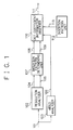
- Fig. 1 schematically shows an information inserter for DCT coefficient coping with conversion of resolution.
- the configuration of Fig. 1 schematically shows an information inserter for DCT coefficient coping with conversion of resolution.
- a resolution analyzer 102 which receives MPEG data of video code data from an input line 104 to output MPEG data to a line 104 and information to a line 105
- an insertion pattern determining unit 107 which receives signals from the lines 10 and 105 to output MPEG data to a line 108 and information to line 109
- an information inserter 110 which receives signals from lines 108, 109, 106 and 113 to output to an output line 111 MPEG data in which information is inserted into DCT coefficients
- a video analyzer 103 which receives MPEG data from the input line 101 to output information to the line 106, and an insertion pattern unit 112 to output a video pattern to the line 113.
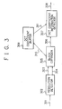
- Fig. 3 illustratively shows an information detector for DCT coefficients coping with conversion of resolution.
- the system of Fig. 3 includes a resolution detector 302 which receives MPEG data from an input line 301 to output MPEG data to a line 303 and information to line 304, a block expander 305 which receives signals from the lines 303 and 304 to expand or to compress information of video signals in 8 (bytes) by 8 (bytes) blocks and which outputs DCT coefficients via a line 310 to a DCT coefficient buffer 309 and a signal to a line 306, and an information detector 307 which receives a signal delivered via the line 306 from the block expander 305 and DCT coefficients from line 311 to output a result of detection to a line 308.
- the DCT is conducted in the unit of 8 (bytes) by 8 (bytes).
- information inserted into blocks in the insertion of information into DCT coefficients is deformed.
- the DCT coefficient information detector 307 must execute processing in the unit of 8 (bytes) by 8 (bytes). Otherwise, calculation steps are increased.
- the information inserted in the DCT coefficients can be detected even in an minimized picture.
- the block expander 305 determines a pattern for which appropriate similarity is attained between the pattern and that of minimized image.
- the DCT coefficient buffer 309 stores therein one screen of video information (DCT coefficients).
- the DCT coefficient information detector detects inserted information using the DCT coefficients for one screen.
- the input pattern unit 112 includes in general an input pattern 112 containing values in blocks in the unit of 8 (bytes) by 8 (bytes).
- Fig. 1 schematically shows constitution of the DCT coefficient information insertion/detection system in accordance with the present invention.
- Fig. 2 illustratively shows operation of the insertion pattern determining unit 107.
- Fig. 3 shows a configuration of the DCT coefficient information detector coping with conversion of resolution in accordance with the present invention.
- Fig. 4 shows an example of operation of the block expander.
- the resolution analyzer 102 of Fig. 1 receives MPEG data from an input line 101, detects an image size of MPEG data, the size recorded in the MPEG data. The analyzer 102 then outputs information of the image size to the line 105 and sends the MPEG data received from the input line 101 directly to the line 104.
- the video analyzer 103 determines, according to DCT coefficients of the MPEG data received from the input line 101, strength of insertion of information in DCT coefficients for each MPEG block and then outputs the insertion strength determined to the line 106.
- the insertion pattern determining unit 107 determines, according to the image size received from the line 105, an insertion pattern to be inserted and then delivers information of the insertion pattern to the line 109.
- the unit 107 also outputs the MPEG data received from the line 104 directly to the line 108.
- the DCT coefficient information inserter 110 inserts an insertion pattern 112 delivered from the line 113 according to the insertion pattern information fed from the line 109 into the DCT coefficients with an insertion strength received from the line 106.
- Fig. 2 shows an example of operation of the insertion pattern determining unit 107.
- the system determines an insertion pattern by assuming that when the MPEG data is expanded into a reference image size, there is obtained a block equal in arrangement to the reference block.
- an insertion pattern is determined for each block of the MPEG data in a small image and the small image is expanded to the reference image size, the entire image is substantially equal to the insertion pattern of the reference image. Consequently, the information of DCT coefficients can be detected.
- an insertion pattern is arranged such that when the image is minimized down to a reference image size, the entire image is substantially equal to the insertion pattern of the reference image.
- the resolution detector 302 of Fig 3 receives MPEG data from the input line 301 and determines an image size of the MPEG data recorded in the MPEG data.
- the detector 302 sends the MPEG data directly to the line 303 and delivers the MPEG data image size to the line 304.
- the block expander 305 outputs, according to DCT coefficients and MPEG information of the MPEG data from the line 303, the DCT coefficients via the line 310 to a predetermined address of the DCT coefficient buffer 309 to add the DCT coefficients to associated items.
- the block expander 305 delivers a signal indicating that one frame of DCT coefficients is completely accumulated and detection of information in DCT coefficients is started.
- the DCT coefficient information detector 307 On receiving a signal from the line 306, the DCT coefficient information detector 307 receives data via the line 312 from the DCT coefficient buffer 309, detects information in the DCT coefficients, and sends a result of detection to the output line 308.
- Fig. 4 shows an example of operation of the block expander 305.
- the block expander 305 determines addresses in the DCT coefficient buffer 309 by assuming that when the MPEG data is expanded to a reference image size, a block resultant from the expansion is the same in arrangement as the reference block.
- the expander 305 determines a write address for each MPEG block.
- the expander 305 weights each DCT coefficients.
- the block expander 305 calculates addresses in the DCT coefficient buffer 309 by assuming that when the image is minimized to the reference image size, a block resultant from the minimization is almost the same in arrangement as a detection pattern of the reference block.
- the information inserted as digital watermark data can be detected.
- the digital watermark can be detected by a watermark inserter/detector implemented by slightly modifying a watermark inserter/detector not coping with image expansion and minimization.
Landscapes
- Engineering & Computer Science (AREA)
- Multimedia (AREA)
- Signal Processing (AREA)
- Physics & Mathematics (AREA)
- Discrete Mathematics (AREA)
- General Physics & Mathematics (AREA)
- Compression Or Coding Systems Of Tv Signals (AREA)
- Transmission Systems Not Characterized By The Medium Used For Transmission (AREA)
- Editing Of Facsimile Originals (AREA)
- Compression Of Band Width Or Redundancy In Fax (AREA)
Abstract
Description
Claims (6)
- An information insertion/detection system for detecting and inserting DCT coefficients in image signals, comprising:a resolution analyzer for receiving image code data and outputting the image code data and information of size of an image of the image code data;an insertion pattern determining unit for receiving the image code data and the image size information and outputting the image code data and pattern information;an information inserter for receiving the image code data and the pattern information and producing image code data by inserting information of the DCT coefficients into the image code data; anda video analyzer for receiving the image code data and producing information of insertion strength of the DCT coefficients.
- An information insertion/detection system for detecting and inserting DCT coefficients in image signals, comprising:a resolution analyzer for receiving image code data and outputting the image code data and information of size of an image of the image code data;an insertion pattern determining unit for receiving the image code data and the image size information and outputting the image code data and pattern information;an information inserter for receiving the image code data and the pattern information and producing image code data by inserting information of the DCT coefficients into the image code data; anda video analyzer for receiving the image code data and producing information of insertion strength of the DCT coefficientssaid image code data is MPEG data; andsaid information inserter receives the image code data and the pattern information and producing image code data by inserting information of the DCT coefficients into the image code data using the insertion strength information of the DCT coefficients.
- The information insertion/detection system in accordance with claim 1 or 2, further comprising an insertion pattern generator for generating a plurality of image insertion patterns,
said insertion pattern generator selecting one of the insertion patterns according to the pattern information from said insertion pattern determining unit and outputting the image code data. - An information insertion/detection system for detecting and inserting DCT coefficients in image signals, comprising:a resolution analyzer for receiving image code data of the image signals and outputting the image code data and image size information of the image code data;a block expander for receiving the image code data and the image size information and outputting DCT coefficients of the image code data and the image code data;a DCT coefficient buffer for receiving the DCT coefficients and outputting, when one frame of DCT coefficients is accumulated, an information detection start signal of the DCT coefficients accumulated therein; anda DCT coefficient information detector for detecting information in the DCT coefficients in response to the information detection start signal and outputting a result of the detection.
- An information insertion/detection system for detecting and inserting DCT coefficients in image signals, comprising:a resolution analyzer for receiving image code data of the image signals and outputting the image code data and image size information of the image code data;a block expander for receiving the image code data and the image size information and outputting DCT coefficients of the image code data and the image code data;a DCT coefficient buffer for receiving the DCT coefficients and outputting, when one frame of DCT coefficients is accumulated, an information detection start signal of the DCT coefficients accumulated therein; anda DCT coefficient information detector for detecting information in the DCT coefficients in response to the information detection start signal and outputting a result of the detection, wherein:said image code data is MPEG data; andsaid block expander outputs, when it is found that the image is smaller than a reference image according to the DCT coefficients and the image size information, the DCT coefficients to said DCT coefficient buffer by assuming that when the image code data is expanded to a reference image size, there is obtained a block which is almost the same in arrangement as a reference image block.
- The system in accordance with claim 3, 4 or 5,
wherein said block expander determines, when it is found that the image is larger than the reference image according to the DCT coefficients and the image size information, addresses in said DCT coefficient buffer by assuming that when the image code data is compressed to the reference image size, there is obtained data which is almost the same in arrangement as a detection pattern of the reference image.
Applications Claiming Priority (2)
| Application Number | Priority Date | Filing Date | Title |
|---|---|---|---|
| JP37491999 | 1999-12-28 | ||
| JP37491999A JP2001189844A (en) | 1999-12-28 | 1999-12-28 | Information inserting and detecting system |
Publications (2)
| Publication Number | Publication Date |
|---|---|
| EP1113670A2 true EP1113670A2 (en) | 2001-07-04 |
| EP1113670A3 EP1113670A3 (en) | 2004-08-04 |
Family
ID=18504657
Family Applications (1)
| Application Number | Title | Priority Date | Filing Date |
|---|---|---|---|
| EP20000128410 Withdrawn EP1113670A3 (en) | 1999-12-28 | 2000-12-27 | System for the insertion or detection of information into image data |
Country Status (4)
| Country | Link |
|---|---|
| US (1) | US6757331B2 (en) |
| EP (1) | EP1113670A3 (en) |
| JP (1) | JP2001189844A (en) |
| KR (1) | KR100420439B1 (en) |
Families Citing this family (9)
| Publication number | Priority date | Publication date | Assignee | Title |
|---|---|---|---|---|
| AUPR970601A0 (en) * | 2001-12-21 | 2002-01-24 | Canon Kabushiki Kaisha | Encoding information in a watermark |
| AU2002320672B2 (en) * | 2001-12-21 | 2005-06-16 | Canon Kabushiki Kaisha | Encoding Information in a Watermark |
| JP4135888B2 (en) | 2002-09-18 | 2008-08-20 | 株式会社リコー | Image processing apparatus, image processing method, program, and storage medium |
| TWI252641B (en) * | 2004-12-17 | 2006-04-01 | Realtek Semiconductor Corp | Searching method for maximum likelihood (ML) detection |
| KR100771620B1 (en) * | 2005-10-18 | 2007-10-30 | 엘지전자 주식회사 | Digital signal transmission method |
| US8565472B2 (en) * | 2007-10-30 | 2013-10-22 | General Instrument Corporation | Method, device and system for dynamically embedding watermark information into multimedia content |
| US20090110059A1 (en) * | 2007-10-31 | 2009-04-30 | General Instrument Corporation | Method and system for transmitting end-user access information for multimedia content |
| US10123031B2 (en) * | 2015-07-02 | 2018-11-06 | Cisco Technology, Inc. | MPEG-2 video watermarking technique |
| CN108650491B (en) * | 2018-05-15 | 2020-07-07 | 西安电子科技大学 | Video watermark detection method for monitoring system |
Family Cites Families (12)
| Publication number | Priority date | Publication date | Assignee | Title |
|---|---|---|---|---|
| DE69840308D1 (en) * | 1997-02-24 | 2009-01-22 | Nec Corp | System for encoding digital data |
| JPH10304176A (en) | 1997-04-24 | 1998-11-13 | Canon Inc | Image processing apparatus and method, and storage medium |
| JP3423585B2 (en) | 1997-08-13 | 2003-07-07 | 日本電信電話株式会社 | Image processing method and apparatus |
| US6108434A (en) * | 1997-09-12 | 2000-08-22 | Signafy, Inc. | Counteracting geometric distortions for DCT based watermarking |
| EP0905967A1 (en) * | 1997-09-26 | 1999-03-31 | Digital Copyright Technologies AG | Method for generating digital watermarks and for exchanging data containing digital watermarks |
| US6208745B1 (en) * | 1997-12-30 | 2001-03-27 | Sarnoff Corporation | Method and apparatus for imbedding a watermark into a bitstream representation of a digital image sequence |
| JPH11268352A (en) | 1998-03-20 | 1999-10-05 | Canon Inc | Image processing apparatus and method, and storage medium |
| CA2332548C (en) * | 1998-05-20 | 2003-10-07 | Macrovision Corporation | Method and apparatus for watermark detection for specific scales and arbitrary shifts |
| JP3156667B2 (en) | 1998-06-01 | 2001-04-16 | 日本電気株式会社 | Digital watermark insertion system, digital watermark characteristic table creation device |
| US6154571A (en) * | 1998-06-24 | 2000-11-28 | Nec Research Institute, Inc. | Robust digital watermarking |
| US6188728B1 (en) * | 1998-09-29 | 2001-02-13 | Sarnoff Corporation | Block motion video coding and decoding |
| US6285775B1 (en) * | 1998-10-01 | 2001-09-04 | The Trustees Of The University Of Princeton | Watermarking scheme for image authentication |
-
1999
- 1999-12-28 JP JP37491999A patent/JP2001189844A/en active Pending
-
2000
- 2000-12-27 EP EP20000128410 patent/EP1113670A3/en not_active Withdrawn
- 2000-12-28 KR KR10-2000-0083833A patent/KR100420439B1/en not_active Expired - Fee Related
- 2000-12-28 US US09/750,519 patent/US6757331B2/en not_active Expired - Fee Related
Also Published As
| Publication number | Publication date |
|---|---|
| KR100420439B1 (en) | 2004-03-04 |
| EP1113670A3 (en) | 2004-08-04 |
| US6757331B2 (en) | 2004-06-29 |
| JP2001189844A (en) | 2001-07-10 |
| KR20010062824A (en) | 2001-07-07 |
| US20010005397A1 (en) | 2001-06-28 |
Similar Documents
| Publication | Publication Date | Title |
|---|---|---|
| US6453053B1 (en) | Identification data insertion and detection system for digital data | |
| US5809041A (en) | Image processing apparatus and method for concealing errors by replacing only part of a block | |
| US6058210A (en) | Using encoding cost data for segmentation of compressed image sequences | |
| EP1139660B1 (en) | System for embedding additional information in video data, and embedding method | |
| JP2931732B2 (en) | Video compression method and decompression method and apparatus using variable length coding | |
| US6307885B1 (en) | Device for and method of coding/decoding image information | |
| US6567562B1 (en) | Encoding apparatus and method | |
| US20010043282A1 (en) | Multi-function USB video capture chip using bufferless data compression | |
| JPH10257502A (en) | Hierarchical image encoding method, hierarchical image multiplexing method, hierarchical image decoding method and apparatus | |
| US6987808B2 (en) | Transcoding method and transcoding apparatus | |
| US6269123B1 (en) | Video encoder and video encoding method | |
| US6757331B2 (en) | Information insertion/detection system | |
| KR100618291B1 (en) | Watermark Detection in Compressed Video Signals | |
| CN112672164B (en) | Video compression system and method, and video decompression system and method | |
| US6947599B2 (en) | Apparatus and method for image compression using a specified restart interval | |
| JP4165752B2 (en) | Secret data insertion method and secret data detection method for image data | |
| JP5080304B2 (en) | Display method of image data with confidential data inserted | |
| US20020064225A1 (en) | Compact MPEG data processing circuit and method of controlling the same | |
| US6970603B2 (en) | Data encoding apparatus and method of same and camera system | |
| JPH07222173A (en) | Image processing device | |
| CA2390904C (en) | Methods and apparatus for dynamically adjusting f-codes for a digital picture header | |
| JP3615086B2 (en) | Compressed data content determination method and compressed data content determination device | |
| JP2000069485A (en) | Moving picture compression device | |
| JP4469643B2 (en) | Image processing circuit | |
| JP2004040673A (en) | Method and apparatus for adding time code to images of surveillance camera |
Legal Events
| Date | Code | Title | Description |
|---|---|---|---|
| PUAI | Public reference made under article 153(3) epc to a published international application that has entered the european phase |
Free format text: ORIGINAL CODE: 0009012 |
|
| AK | Designated contracting states |
Kind code of ref document: A2 Designated state(s): AT BE CH CY DE DK ES FI FR GB GR IE IT LI LU MC NL PT SE TR |
|
| AX | Request for extension of the european patent |
Free format text: AL;LT;LV;MK;RO;SI |
|
| PUAL | Search report despatched |
Free format text: ORIGINAL CODE: 0009013 |
|
| AK | Designated contracting states |
Kind code of ref document: A3 Designated state(s): AT BE CH CY DE DK ES FI FR GB GR IE IT LI LU MC NL PT SE TR |
|
| AX | Request for extension of the european patent |
Extension state: AL LT LV MK RO SI |
|
| 17P | Request for examination filed |
Effective date: 20040706 |
|
| 17Q | First examination report despatched |
Effective date: 20041129 |
|
| AKX | Designation fees paid |
Designated state(s): DE FR GB NL |
|
| RBV | Designated contracting states (corrected) |
Designated state(s): DE FR GB NL |
|
| RAP1 | Party data changed (applicant data changed or rights of an application transferred) |
Owner name: NEC PERSONAL COMPUTERS, LTD. |
|
| STAA | Information on the status of an ep patent application or granted ep patent |
Free format text: STATUS: THE APPLICATION IS DEEMED TO BE WITHDRAWN |
|
| 18D | Application deemed to be withdrawn |
Effective date: 20160701 |