EP1113644A2 - Data transfer method and radio terminal for executing transport layer protocol on radio network - Google Patents
Data transfer method and radio terminal for executing transport layer protocol on radio network Download PDFInfo
- Publication number
- EP1113644A2 EP1113644A2 EP00311693A EP00311693A EP1113644A2 EP 1113644 A2 EP1113644 A2 EP 1113644A2 EP 00311693 A EP00311693 A EP 00311693A EP 00311693 A EP00311693 A EP 00311693A EP 1113644 A2 EP1113644 A2 EP 1113644A2
- Authority
- EP
- European Patent Office
- Prior art keywords
- logical channel
- radio terminal
- transfer
- terminal device
- radio
- Prior art date
- Legal status (The legal status is an assumption and is not a legal conclusion. Google has not performed a legal analysis and makes no representation as to the accuracy of the status listed.)
- Granted
Links
Images








Classifications
-
- H—ELECTRICITY
- H04—ELECTRIC COMMUNICATION TECHNIQUE
- H04L—TRANSMISSION OF DIGITAL INFORMATION, e.g. TELEGRAPHIC COMMUNICATION
- H04L67/00—Network arrangements or protocols for supporting network services or applications
- H04L67/14—Session management
-
- H—ELECTRICITY
- H04—ELECTRIC COMMUNICATION TECHNIQUE
- H04L—TRANSMISSION OF DIGITAL INFORMATION, e.g. TELEGRAPHIC COMMUNICATION
- H04L65/00—Network arrangements, protocols or services for supporting real-time applications in data packet communication
- H04L65/1066—Session management
- H04L65/1101—Session protocols
-
- H—ELECTRICITY
- H04—ELECTRIC COMMUNICATION TECHNIQUE
- H04L—TRANSMISSION OF DIGITAL INFORMATION, e.g. TELEGRAPHIC COMMUNICATION
- H04L65/00—Network arrangements, protocols or services for supporting real-time applications in data packet communication
- H04L65/60—Network streaming of media packets
- H04L65/65—Network streaming protocols, e.g. real-time transport protocol [RTP] or real-time control protocol [RTCP]
-
- H—ELECTRICITY
- H04—ELECTRIC COMMUNICATION TECHNIQUE
- H04W—WIRELESS COMMUNICATION NETWORKS
- H04W80/00—Wireless network protocols or protocol adaptations to wireless operation
Definitions
- the present invention relates to a radio terminal belonging to a radio network for carrying out communications by setting up logical channels on a radio network in advance and an information transfer method of a radio terminal.
- radio network radio LAN
- RTP Realtime Transport Protocol
- the RTP is a protocol for which the standardization by the IETF has already been completed and it is already the Standard-Track RFC 1889 (A Transport Protocol for Real-time Applications).
- a radio terminal device for use in a radio system for carrying out data transfer after establishing a logical connection between radio terminals prior to data transfer between radio terminals
- the radio terminal device comprising: a logical channel set up unit configured to set up at least one first logical channel for transfer of data packets containing at least one AV stream and acquire information regarding at least one second logical channel set up for the transfer of the data packets at a correspondent radio terminal, and to set up at least one third logical channel for transfer of control packets containing control information regarding transfer of the data packets and acquire information regarding at least one fourth logical channel set up for the transfer of the control packets at the correspondent radio terminal; a memory unit configured to store a correspondence information including a correspondence between the first logical channel and the second logical channel for the AV stream, and a correspondence between the third logical channel and the fourth logical channel for the control information; and a packet transmission/reception unit configured to transmit/receive the data packets and the control packets to/from the
- a data transfer method in a radio system for carrying out data transfer after establishing a logical connection between radio terminals prior to data transfer between radio terminals, the method comprising the steps of: setting up at least one first logical channel for transfer of data packets containing at least one AV stream and acquiring information regarding at least one second logical channel set up for the transfer of the data packets at a correspondent radio terminal, and setting up at least one third logical channel for transfer of control packets containing control information regarding transfer of the data packets and acquiring information regarding at least one fourth logical channel set up for the transfer of the control packets at the correspondent radio terminal; storing a correspondence information including a correspondence between the first logical channel and the second logical channel for the AV stream, and a correspondence between the third logical channel and the fourth logical channel for the control information; and transmitting/receiving the data packets and the control packets to/from the correspondent radio terminal by using the correspondence information.
- a computer usable medium having computer readable program codes embodied therein for causing a computer to function as a radio terminal device for use in a radio system for carrying out data transfer after establishing a logical connection between radio terminals prior to data transfer between radio terminals
- the computer readable program codes include: a first computer readable program code for causing said computer to set up at least one first logical channel for transfer of data packets containing at least one AV stream and acquire information regarding at least one second logical channel set up for the transfer of the data packets at a correspondent radio terminal, and to set up at least one third logical channel for transfer of control packets containing control information regarding transfer of the data packets and acquire information regarding at least one fourth logical channel set up for the transfer of the control packets at the correspondent radio terminal; a second computer readable program code for causing said computer to store a correspondence information including a correspondence between the first logical channel and the second logical channel for the AV stream, and a correspondence between the third logical channel and
- Fig. 1 is a diagram showing a protocol stack to be executed by a radio terminal in the first embodiment of the present invention.
- Fig. 2 is a schematic diagram showing an exemplary configuration of a radio network using a radio terminal according to the first embodiment of the present invention.
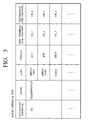
- Fig. 3 is a diagram showing an exemplary correspondence table of logical channels to be stored at one radio terminal according to the first embodiment of the present invention.
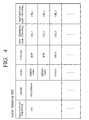
- Fig. 4 is a diagram showing an exemplary correspondence table of logical channels to be stored at another radio terminal according to the first embodiment of the present invention.
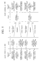
- Fig. 5 is a sequence chart showing a first part of one exemplary processing sequence for a logical channel set up at a time of AV data transfer between radio terminals according to the first embodiment of the present invention.
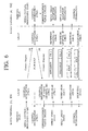
- Fig. 6 is a sequence chart showing a second part of one exemplary processing sequence for a logical channel set up at a time of AV data transfer between radio terminals according to the first embodiment of the present invention.
- Fig. 7 is a diagram showing exemplary packet formats of an RTP packet and an RTCP packet to be transferred between radio terminals according to the first embodiment of the present invention.
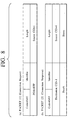
- Fig. 8 is a diagram showing exemplary header formats of first two packets to be transferred between radio terminals in the processing sequence of Fig. 5 and Fig. 6.
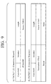
- Fig. 9 is a diagram showing exemplary header formats of next two packets to be transferred between radio terminals in the processing sequence of Fig. 5 and Fig. 6.
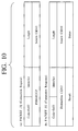
- Fig. 10 is a diagram showing exemplary header formats of next two packets to be transferred between radio terminals in the processing sequence of Fig. 5 and Fig. 6.
- Fig. 11 is a sequence chart showing a first part of another exemplary processing sequence for a logical channel set up at a time of AV data transfer between radio terminals according to the first embodiment of the present invention.
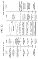
- Fig. 12 is a sequence chart showing a second part of another exemplary processing sequence for a logical channel set up at a time of AV data transfer between radio terminals according to the first embodiment of the present invention.
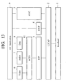
- Fig. 13 is a diagram showing a protocol stack to be executed by a radio terminal in the second embodiment of the present invention.
- Fig. 14 is a schematic diagram showing an exemplary configuration of a radio network using a radio terminal according to the second embodiment of the present invention.
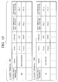
- Fig. 15 is a diagram showing exemplary correspondence tables of logical channels to be stored at radio terminals according to the second embodiment of the present invention.
- Fig. 16 is a sequence chart showing a first part of one exemplary processing sequence for a logical channel set up at a time of AV data transfer between radio terminals according to the second embodiment of the present invention.
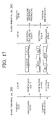
- Fig. 17 is a sequence chart showing a second part of one exemplary processing sequence for a logical channel set up at a time of AV data transfer between radio terminals according to the second embodiment of the present invention.
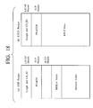
- Fig. 18 is a diagram showing exemplary packet formats of an RTP packet and an RTCP packet to be transferred between radio terminals according to the second embodiment of the present invention.
- Fig. 19 is a sequence chart showing an exemplary processing sequence for a logical channel set up at a time of AV data transfer between radio terminals according to the third embodiment of the present invention.
- Fig. 20 is a block diagram showing an exemplary configuration of a radio terminal device according to the present invention.
- a radio system for carrying out data transfer after establishing a logical connection between radio terminals prior to data transfer between radio terminals in the case of transferring data packets containing a single AV stream or one AV stream in which a plurality of single streams are multiplexed while exchanging control packets containing control information regarding transfer of the data packets containing the AV stream, different logical channels are assigned to the data packets containing the AV stream and the control packets containing the control information so that the data packets and the control packets are transferred by these different logical channels.
- the data packets and the control information are transferred by different logical channels even in the case of assigning a logical channel to each one of a plurality of AV streams belonging to a single AV application separately.
- the MPEG4 video/audio data and the control information are transferred by different logical channels, or in the case where the MPEG4 video data and the MPEG4 audio data are multiplexed by the H.223 protocol, for example, the H.223 packets and the control packets are transferred by different logical channels.
- the present invention it becomes possible to realize the AV data transfer processing utilizing the transport layer protocol such as RTP protocol, between radio terminals in a radio system for carrying out data transfer after establishing a logical connection between radio terminals prior to data transfer between radio terminals such as Bluetooth.
- transport layer protocol such as RTP protocol
- the AV data transfer control processing can be made easier.
- the radio LAN system is assumed to be a radio system for carrying out data transfer after establishing a logical connection between radio terminals prior to data transfer between radio terminals. More specifically, the following embodiments are directed to the exemplary case of using the Bluetooth which is a known example of such a radio LAN system.
- Fig. 1 shows an exemplary protocol stack for the AV data transfer scheme to be executed in this first embodiment.
- the protocol stack of Fig. 1 is for the case of using the Bluetooth (in which the physical layer is Baseband and the datalink layer is L2CAP) that is currently in a process of the standardization, as the radio system.
- the Bluetooth in which the physical layer is Baseband and the datalink layer is L2CAP
- the protocol stack of Fig. 1 is also for the case of executing the AV/C protocol as defined by the IEEE 1394 as the AV control protocol for transferring AV data and thereby providing a function such as the so called session control processing, at a time of executing an AV application at the radio terminal.
- the protocol stack of Fig. 1 is also for the case where the actual AV data transfer is carried out such that various data such as video data, audio data and information data are transferred by respective RTP (Realtime Transport Protocol) packets, the RTP packets are further encapsulated into L2CAP packets according to the datalink layer protocol of the Bluetooth, and the AV data transfer control information is exchanged using the RTCP (RTP Control Protocol) protocol.
- RTP Realtime Transport Protocol
- RTCP RTP Control Protocol
- This embodiment is directed to the case of transferring various data (video, audio, information) as respective different RTP streams as shown in the protocol stack of Fig. 1, where the RTCP protocol is executed as a protocol for exchanging information such as AV data transfer state (error rate, etc.) regarding each RTP stream.
- the RTP packet and the RTCP packet have basically the same packet format (defined by RFC 1889), and it is possible to distinguish these packets according to information of a packet header field, but in this embodiment, these packets are distinguished by transferring them using different L2CAP channels.
- Fig. 1 shows an internal configuration regarding the protocol processing of the radio terminal, which includes processing units for executing respective protocols, i.e., a Baseband processing unit 1 for executing the physical layer processing of the Bluetooth, an L2CAP processing unit 2 for executing the datalink layer processing of the Bluetooth, an AV/C protocol processing unit 3 for executing the AV/C protocol at an upper layer of the L2CAP processing unit 2, RTP processing units 4 for executing the RTP protocol, various processing units including a Video processing unit 6, an Audio processing unit 7, and Data processing unit 8 which are provided at an upper layer of the RTP processing unit 4 and corresponding to a group of AV data transfer protocols, an RTCP processing unit 5 for executing the RTCP protocol, and an AV application processing unit 9 for executing an AV application at an upper layer of the above described processing units.
- a Baseband processing unit 1 for executing the physical layer processing of the Bluetooth
- an L2CAP processing unit 2 for executing the datalink layer processing of the Bluetooth
- an AV/C protocol processing unit 3 for
- the AV/C protocol recognizes nodes in terms of Units, and constituent elements (such as Display or VTR, for example) within each node in terms of SubUnits. Also, in the protocol for transferring the AV/C control commands (commands such as "play”, “stop”, “fast forward”, etc.), a transmission of a command and a reception of a response are to be carried out as one set.
- Fig. 2 shows an exemplary configuration of a radio network in the case of carrying out the AV data transfer by the protocol stack as described above.
- a radio terminal 101 and a radio terminal 102 are connected to a Bluetooth network 10, and an MPEG4 video/audio source (SubUnit) 1011 which is a function for providing MPEG4 video/audio sources such as VTR for example is provided in the radio terminal 101, while an MPEG4 decoder/viewer function (SubUnit) 1021 which is a function for decoding the MPEG4 video/audio data and presenting (displaying/audio outputting) the decoded video/audio data to a user is provided in the radio terminal 102.
- an MPEG4 video/audio source SubUnit
- SubUnit MPEG4 decoder/viewer function
- the MPEG4 video/audio source 1011 of the radio terminal 101 may be the MPEG4 video/audio data received from another device that are related by the radio terminal 101.
- the MPEG4 decoder/viewer function 1021 of the radio terminal 102 may be the MPEG4 decoder viewer function in another device to which the received MPEG4 video/audio data are relayed by the radio terminal 102.
- each one of the radio terminal 101 and the radio terminal 102 maintains a correspondence between the AV data transferred and the L2CAP logical channels as follows.
- Fig. 3 shows an exemplary correspondence table for the AV data and the L2CAP logical channels maintained by the radio terminal 101.
- an L2CAP logical channel corresponding to each RTP/RTCP stream is indicated. More specifically, in the case of Fig.
- Fig. 4 shows an exemplary correspondence table for the AV data the L2CAP logical channels maintained by the radio terminal 102.
- the correspondence table of Fig. 4 is configured similarly as that of Fig. 3 such that information on the AV data received by the radio terminal 102 and the L2CAP logical channels assigned to the AV data transfer control data can be obtained from this correspondence table.
- Fig. 5 and Fig. 6 show an exemplary processing sequence in this case.
- Fig. 5 and Fig. 6 are showing one series of processing in which the processing of Fig. 5 is to be followed by the processing of Fig. 6. Note however that various procedures can be carried out simultaneously or interchanged according to the need as will be described below.
- Fig. 5 shows the processing starting from the MPEG4 video data transmission processing (so that the processings corresponding to the procedures (1) and (2) of Fig. 2 are omitted here).
- the necessary data communication can be carried out according to the need (the destination logical channels corresponding to the data to be transmitted (the MPEG4 video data, the MPEG4 audio data, and the control information in this example) can be obtained by referring to the channel correspondence table), as follows.
- the exemplary processing sequence described above sequentially carries out the set up of the three L2CAP logical channels, but there is no need to carry out these processings for acquiring the L2CAP logical channels in this order.
- the processings for acquiring these three logical channels may be carried out in parallel, or the order for carrying out these processings may be interchanged.
- the L2CAP logical channel number to be assigned to the Video stream there are various methods available for the assignment of the L2CAP logical channel number to be assigned to the Video stream, the L2CAP logical channel number to be assigned to the Audio stream, and the L2CAP logical channel number for the transfer of the control information for the transfer control.
- the logical channel numbers are assigned such that, if the L2CAP logical channel numbers up to No. 8 are already utilized at the radio terminal 101 of Fig. 2, at a time of transfer of a new AV stream data, the logical channel No. 9 is assigned to the Video stream, the logical channel No. 10 is assigned to the Audio stream, and the logical channel No. 11 is assigned to the control information transfer, for example.
- the logical channel for the exchange of the control information is set up with respect to one AV application (one session), rather than assigning the L2CAP logical channel for the exchange of the control information for each AV stream (the Video stream and the Audio stream in the above example). More specifically, the RTCP protocol is executed with respect to one AV application (session). However, the method for executing the RTCP protocol is not necessarily limited to this particular case.
- a logical channel for the RTCP for each AV stream (the logical channel No. 1 and No. 2 on the radio terminal 101 set up in the example of Fig. 5 and Fig. 6).
- the logical channel No. 1 and No. 2 on the radio terminal 101 set up in the example of Fig. 5 and Fig. 6 two channels may be used as the L2CAP logical channel for the video data transfer control and the L2CAP logical channel for the audio data transfer control.
- an intermediate form of the two methods described above that is, a method for carrying out the exchange of the control information by acquiring m sets of logical channels for the RTCP with respect to n (1 ⁇ m ⁇ n) sets of AV streams belonging to one AV application (in which case the n sets of AV streams will be suitably distributed among the m sets of logical channels for the RTCP).
- Such a method for setting up the logical channels for the control information exchange can be notified by a preliminary set up procedure (session establishing procedure) or the like before the execution of each AV application.
- a preliminary set up procedure session establishing procedure
- the control information is exchanged by describing the control information in the Descriptor (attribute information description) of the AV/C in advance and reading it beforehand, by applying the AV/C protocol to this session establishing procedure.
- an RTP header is provided next to an L2CAP header (that contains the packet length and the channel ID) of each packet, and whether this packet is the RTP packet of the RTCP packet can be identified by a PT (Payload Type) field in this RTP header.
- the RTP packet header is accompanied by an MPEG4_Specific_Header for the purpose of providing functions for identifying whether the loaded data are the MPEG4 video data or the MPEG4 audio data, and identifying the encoding scheme of the loaded data. Note however that this MPEG4_Specific_Header is not an absolutely necessary field in the case where such information can be notified in advance by the earlier exchange of the session control information.
- Figs. 8, 9 and 10 show examples of the header region in the Connect_Request packet (packets [1], [3], [5]) and the Connect_Response packet (packets [2], [4], [6]) that are transferred in the series of processing shown in Fig. 5 and Fig. 6.
- a part (a) of Fig. 8 corresponds to the packet [1]
- a part (b) of Fig. 8 corresponds to the packet [2]
- a part (a) of Fig. 9 corresponds to the packet [3]
- a part (b) of Fig. 9 corresponds to the packet [4]
- a part (a) of Fig. 10 corresponds to the packet [5]
- a part (b) of Fig. 10 corresponds to the packet [6].
- PSM Protocol Service Multiplexor
- the information contained in the header region of the packet [3] is similar to that of the packet [1]
- the information contained in the header region of the packet [4] is similar to that of the packet [2].
- Fig. 11 and Fig. 12 show an exemplary processing sequence in this case.
- Fig. 11 and Fig. 12 are showing one series of processing in which the processing of Fig. 11 is to be followed by the processing of Fig. 12. Note however that various procedures can be carried out simultaneously or interchanged according to the need as will be described below.
- Fig. 11 shows the processing starting from the MPEG4 video data transmission processing (so that the processings corresponding to the procedures (1) and (2) of Fig. 2 are omitted here).
- the procedure of Fig. 11 and Fig. 12 differs from the procedure of Fig. 5 and Fig. 6 in the method for creating the correspondence table of the logical channel numbers in the radio terminal 102 which is the receiving side terminal.
- the radio terminal 102 does not create the correspondence table of the logical channels at a time of setting up the individual L2CAP logical channel, and the correspondence table is notified by using the AV/C command after the logical channel set up is finished.
- the necessary data communication can be carried out according to the need (the destination logical channels corresponding to the data to be transmitted (the MPEG4 video data, the MPEG4 audio data, and the control information in this example) can be obtained by referring to the channel correspondence table), as follows.
- the information to be notified from the radio terminal 101 to the radio terminal 102 in the session notification processing in the above described series of processing can be the correspondence of the L2CAP logical channels that is stored at the radio terminal 101 as shown in Fig. 3 (in this case, the radio terminal 102 creates the correspondence table as shown in Fig. 4 from the correspondence shown in Fig. 3 that is notified from the radio terminal 101).
- processings for acquiring the L2CAP logical channels may be carried out in parallel, or the order for carrying out these processings may be interchanged, similarly as in the case of Fig. 5 and Fig. 6.
- Fig. 13 shows an exemplary protocol stack for the AV data transfer scheme to be executed in this embodiment.
- the protocol stack of Fig. 13 is for the case of using the Bluetooth (in which the physical layer is Baseband and the datalink layer is L2CAP) that is currently in a process of the standardization, as the radio system.
- the Bluetooth in which the physical layer is Baseband and the datalink layer is L2CAP
- the protocol stack of Fig. 13 is also for the case of executing the AV/C protocol as defined by the IEEE 1394 as the AV control protocol for transferring AV data and thereby providing a function such as the so called session control processing, at a time of executing an AV application at the radio terminal.
- the protocol stack of Fig. 13 is for the case where the video/audio data are to be transferred after multiplexing by the H.223 protocol (at an H.223 processing unit 41) and then encapsulating into the RTP packets.
- This RTP stream is further encapsulated into L2CAP packets according to the datalink layer protocol of the Bluetooth.
- This embodiment is directed to the case of transferring various data (video, audio, information) by the RTP protocol after multiplexing the various data into one H.223 stream, where the RTCP protocol is executed as a protocol for exchanging information such as AV data transfer state (error rate, etc.) regarding each RTP stream.
- the RTP packet and the RTCP packet are transferred by using different L2CAP channels.
- Fig. 14 shows an exemplary configuration of a radio network in the case of carrying out the AV data transfer by the protocol stack as described above.
- a radio terminal 201 and a radio terminal 202 are connected to a Bluetooth network 20, and an MPEG4 video/audio source (SubUnit) 2011 which is a function for providing MPEG4 video/audio sources such as VTR for example is provided in the radio terminal 201, while an MPEG4 decoder/viewer function (SubUnit) 2021 which is a function for decoding the MPEG4 video/audio data and presenting (displaying/audio outputting) the decoded video/audio data to a user is provided in the radio terminal 202.
- an MPEG4 video/audio source SubUnit 2011 which is a function for providing MPEG4 video/audio sources such as VTR for example
- an MPEG4 decoder/viewer function (SubUnit) 2021 which is a function for decoding the MPEG4 video/audio data and presenting (displaying/audio outputting) the decoded video/audio data to a user is provided in the radio terminal 202.
- the MPEG4 video/audio source 2011 of the radio terminal 201 may be the MPEG4 video/audio data received from another device that are related by the radio terminal 201.
- the MPEG4 decoder/viewer function 2021 of the radio terminal 202 may be the MPEG4 decoder viewer function in another device to which the received MPEG4 video/audio data are relayed by the radio terminal 202.
- each one of the radio terminal 201 and the radio terminal 202 maintains a correspondence between the AV data transferred and the L2CAP logical channels as follows.
- Parts (a) and (b) of Fig. 15 show exemplary correspondence tables for the AV data and the L2CAP logical channels maintained by the radio terminal 201 and the radio terminal 202.
- the correspondence tables of Fig. 15 are basically similar to those of Fig. 3 and Fig. 4, but as the AV data to be transferred to each radio terminal, it is described that MPEG4 video/audio data multiplexed by the H.223 protocol are transferred by the RTP stream, and the control information for the transfer control of these AV data is transferred by the RTCP stream.
- Fig. 16 and Fig. 17 show an exemplary processing sequence in this case. Note that Fig. 16 and Fig. 17 are showing one series of processing in which the processing of Fig. 16 is to be followed by the processing of Fig. 17. Note however that various procedures can be carried out simultaneously or interchanged according to the need as will be described below. Note also that Fig. 16 shows the processing starting from the MPEG4 video data transmission processing (so that the processings corresponding to the procedures (1) and (2) of Fig. 14 are omitted here).
- the necessary data communication can be carried out according to the need (the destination logical channels corresponding to the data to be transmitted (the H.223 data and the control information in this example) can be obtained by referring to the channel correspondence table), as follows.
- the exemplary processing sequence described above sequentially carries out the set up of the two L2CAP logical channels, but there is no need to carry out these processings for acquiring the L2CAP logical channels in this order.
- the processings for acquiring these two logical channels may be carried out in parallel, or the order for carrying out these processings may be interchanged.
- the packet formats shown in Fig. 18 differ from those shown in Fig. 7 in that an H.223 header region is provided in the payload section of the RTP packet, and that the MPEG4 video data and audio data are loaded in the multiplexed form.
- Fig. 18 shows the case where one H.223 packet multiplexing the MPEG4 video/audio data is loaded on one RTP packet, but it is also possible to use an encapsulation method in which one H.223 packet is transferred by being divided into a plurality of RTP packet, or an encapsulation method in which a plurality of H.223 packets are transferred by being multiplexed into one RTP packet.
- the scheme for multiplexing AV streams as described above in this embodiment is not limited to the H.223 protocol.
- the important point in this embodiment lies in that the AV streams that are multiplexed by some multiplexing protocol are transferred after being encapsulated into the RTP packets.
- One possible way of specifying set up of all logical channels related to the data communication on one radio terminal is to use a protocol identifier (PSM) and one parameter value x (in which case, the protocol identifier and the one parameter value x will be notified from the one radio terminal to another radio terminal).
- PSM protocol identifier
- one parameter value x in which case, the protocol identifier and the one parameter value x will be notified from the one radio terminal to another radio terminal.
- the audio data and the control information for example, any of AV-typel to AV-type6 can be set as the protocol identifier, where:
- AV-typel indicates video data (RTP) + audio data (RTP) + control information (RTCP) (which implies that three logical channels for the video data, the audio data and the control information should be set up, and the acquired logical channels f1(x), f2(x) and f3(x) should be assigned to the video data, the audio data and the control information in this order (although of course the order is not necessarily limited to this and can be predetermined in any suitable order), and the similar explanation also applies to the following);
- the protocol identifier AV-typel
- the logical channel numbers f1(x), f2(x) and f3(x) are assigned in this order (to the video data, the audio data and the control information in this order, for example).
- the protocol identifier AV-type2
- the logical channel numbers f1(x) and f2(x) are assigned to the video data and the control information in this order.
- the logical channel numbers f1(x) and f2(x) that can be acquired are assigned to the audio data and the control information in this order. The other cases are also similarly handled.
- Fig. 19 shows an exemplary processing sequence in thee case of setting up all logical channels by one Connect_Request which is based on the case of Fig. 5 and Fig. 6. Note that Fig. 19 shows the processing starting from the MPEG4 video data transmission processing (so that the processings corresponding to the procedures (1) and (2) of Fig. 2 are omitted here).
- the necessary data communication can be carried out according to the need (the destination logical channels corresponding to the data to be transmitted (the MPEG4 video data, the MPEG4 audio data, and the control information in this example) can be obtained by referring to the channel correspondence table), as follows.
- the above described specific example is directed to the case where a group of functions for specifying the logical channel numbers from the parameter x are predetermined, but it is also possible to provide a plurality of function groups and notify which function group should be used also as the parameter.
- the present invention it becomes possible to realize the AV data transfer processing utilizing the transport layer protocol such as RTP protocol, even in the case of utilizing a radio system which starts the data transfer after establishing a logical connection in advance such as Bluetooth.
- the embodiments described above are directed to the case of transferring the video data and the audio data, but the present invention is also applicable to the case of transferring the other information in addition to the video data and the audio data, the case of transferring only the video data, the case of transferring only the audio data, the case of transferring one of the video data and the audio data and the other information, etc.
- the above described embodiments are directed to the case of using the unidirectional communication for the AV data, but the present invention is also applicable to the case of using the bidirectional communication for the AV data.
- the above described embodiments are directed to the case where the AV data transmitting side transmits the Connect_Request packet after receiving the playback request, and the AV data receiving side transmits the Connect_Response packet in response to that, but it is also possible to adopt the scheme in which the AV data transmitting side transmits a reception request, the AV data receiving side transmits the Connect_Request packet after receiving the reception request, and the AV data transmitting side transmits the Connect_Response packet in response to that.
- the configuration described above is applicable not only to a radio terminal but also to a radio gateway for connecting the Internet and the radio network, for example.
- the above described embodiments are directed to the exemplary case of using the Bluetooth, but the present invention is also applicable to radio terminals of any other radio LAN system for carrying out data transfer after establishing a logical connection between radio terminals prior to data transfer between radio terminals.
- the above described embodiments are directed to the exemplary case of using the AV/C protocol as the AV control protocol for the AV data transfer, but the present invention is also applicable to the case of using any other AV control protocol.
- the above described embodiments are directed to the exemplary case of using the RTP protocol (RTCP protocol) as a protocol for transferring the AV data and their control information, but the present invention is also applicable to the case of using any other protocol for transferring the AV data transfer control information.
- RTP protocol RTCP protocol
- the above described embodiments are directed to the case of using the H.223 protocol for the purpose of multiplexing the AV data, but the present invention is also applicable to the case of using any other multiplexing protocol.
- the present invention is equally applicable to a home network and a network provided in an office or any other environment.
- each radio terminal in the above described embodiments can be realized by a radio terminal device 50 as shown in Fig. 20, for use in a radio system for carrying out data transfer after establishing a logical connection between radio terminals prior to data transfer between radio terminals.
- This radio terminal device 50 of Fig. 20 comprises: a logical channel set up unit 51 for setting up at least one first logical channel for transfer of data packets containing at least one AV stream and acquiring information regarding at least one second logical channel set up for the transfer of the data packets at a correspondent radio terminal, and setting up at least one third logical channel for transfer of control packets containing control information regarding transfer of the data packets and acquiring information regarding at least one fourth logical channel set up for the transfer of the control packets at the correspondent radio terminal; a memory unit 52 for storing a correspondence information including a correspondence between the first logical channel and the second logical channel for the AV stream, and a correspondence between the third logical channel and the fourth logical channel for the control information; a packet transmission/reception unit 53 for transmitting/receiving the data packets and the control packets to/from the correspondent radio terminal by using the correspondence information; and a radio terminal processing unit 54 for controlling the logical channel set up unit 51 and the packet transmission/reception unit 53 according to the protocols
- the logical channel set up unit 51 sets up one first logical channel with respect to the single AV stream or the one AV stream and acquires information regarding one second logical channel set up with respect to the single AV stream or the one AV stream, and sets up one third logical channel with respect to the single AV stream or the one AV stream and acquires information regarding one fourth logical channel set up with respect to the single AV stream or the one AV stream.
- the logical channel set up unit 51 sets up one first logical channel with respect to each one of the plurality of AV streams separately and acquires information regarding one second logical channel set up with respect to each one of the plurality of AV streams separately.
- the logical channel set up unit 51 may set up one third logical channel with respect to the plurality of AV streams and acquire information regarding one fourth logical channel set up with respect to the plurality of AV streams.
- the logical channel set up unit 51 may set up one third logical channel with respect to each one of the plurality of AV streams separately and acquires information regarding one fourth logical channel set up with respect to each one of the plurality of AV streams separately.
- the packet transmission/reception unit 53 transmits the data packets by using the second logical channel obtained by referring to the correspondence information, transmits the control packets by using the fourth logical channel obtained by referring to the correspondence information, and receives the control packets from the correspondent radio terminal by using the third logical channel.
- the logical channel set up unit 51 can transmit a first connection request containing a channel identifier for identifying the first logical channel set up at the radio terminal device 50 to the correspondent radio terminal, and then receive a first connection response containing a channel identifier for identifying the second logical channel set up at the correspondent radio terminal in response to the first connection request, and transmit a second connection request containing a channel identifier for identifying the third logical channel set up at the radio terminal device 50 to the correspondent radio terminal, and then receive a second connection response containing a channel identifier for identifying the fourth logical channel set up at the correspondent radio terminal in response to the second connection request.
- the logical channel set up unit 51 may acquire the information regarding the second logical channel from the first connection response and the information regarding the fourth logical channel from the second connection response, and register the correspondence information into the memory unit 52 according to the information regarding the second logical channel and the information regarding the fourth logical channel as acquired.
- the logical channel set up unit 51 can set up the first logical channel and the third logical channel collectively, and then transmits a connection request containing information for specifying a group of channel identifiers for identifying the first logical channel and the third logical channel set up at the radio terminal device 50 to the correspondent radio terminal.
- the logical channel set up unit 51 may receive a connection response containing information for specifying a group of channel identifiers for identifying the second logical channel and the fourth logical channel set up at the correspondent radio terminal in response to the connection request, and acquires the information regarding the second logical channel and the information regarding the fourth logical channel from the information for specifying the group of identifiers as obtained in the connection response, and registers the correspondence information into the memory unit according to the information regarding the second logical channel and the information regarding the fourth logical channel as acquired.
- the information for specifying the group of identifiers can indicate a prescribed parameter value and a group of functions for generating a prescribed number of channel identifiers from the prescribed parameter value, and the group of functions can generate the prescribed number of channel identifiers in forms of consecutive channel numbers.
- the logical channel set up unit 51 can notify information for specifying a group of channel identifiers for identifying the first logical channel and the third logical channel to the correspondent radio terminal and then set up the first logical channel and the third logical channel collectively.
- the logical channel set up unit 51 can receive a first connection request containing a channel identifier for identifying the second logical channel set up at the correspondent radio terminal from the correspondent radio terminal, and then transmit a first connection response containing a channel identifier for identifying the first logical channel set up at the radio terminal device 50 to the correspondent radio terminal in response to the first connection request, and receive a second connection request containing a channel identifier for identifying the fourth logical channel set up at the correspondent radio terminal from the correspondent radio terminal, and then transmit a second connection response containing a channel identifier for identifying the third logical channel set up at the radio terminal device 50 to the correspondent radio terminal in response to the second connection request.
- the logical channel set up unit 51 may acquire the information regarding the second logical channel from the first connection request and the information regarding the fourth logical channel from the second connection request, and register the correspondence information into the memory unit 52 according to the information regarding the second logical channel and the information regarding the fourth logical channel as acquired.
- the logical channel set up unit 51 may receive a notification of information for specifying a group of channel identifiers for identifying the first logical channel and the third logical channel from the correspondent radio terminal and then set up the second logical channel and the fourth logical channel collectively.
- the radio terminal device 50 of Fig. 20 may further comprises either one or both of a notification unit 55 for notifying the correspondent information stored in the memory unit 52 to the correspondent radio terminal, and a notification reception unit 56 for receiving a notification of the correspondent information obtained at the correspondent radio terminal from the correspondent radio terminal and registering the correspondence information into the memory unit 52 according to the notification.
- the logical channel set up unit 51 sets up and acquires information on logical channels which are LSCAP channels.
- the AV stream can be given by data according to an RTP protocol and the control information can be given by data according to an RTCP protocol.
- the radio terminal and the radio of each of the above described embodiments can be conveniently implemented in a form of a software package.
- Such a software package can be a computer program product which employs a storage medium including stored computer code which is used to program a computer to perform the disclosed function and process of the present invention.
- the storage medium may include, but is not limited to, any type of conventional floppy disks, optical disks, CD-ROMs, magneto-optical disks, ROMs, RAMs, EPROMs, EEPROMs, magnetic or optical cards, or any other suitable media for storing electronic instructions.
Landscapes
- Engineering & Computer Science (AREA)
- Multimedia (AREA)
- Computer Networks & Wireless Communication (AREA)
- Signal Processing (AREA)
- Business, Economics & Management (AREA)
- General Business, Economics & Management (AREA)
- Mobile Radio Communication Systems (AREA)
- Small-Scale Networks (AREA)
- Communication Control (AREA)
- Compression Or Coding Systems Of Tv Signals (AREA)
Abstract
Description
- The
radio terminal 101 acquires CH = 1 for the video data transfer, CH = 2 for the audio data transfer, and CH = 3 for the AV data transfer control. - The
radio terminal 102 acquires CH = 4 for the video data transfer, CH = 5 for the audio data transfer, and CH = 6 for the AV data transfer control.
- The
radio terminal 102 transmits the Play command to theradio terminal 101 by using the AV/C protocol, so as to request transfer of the MPEG4 video/audio data. - The
radio terminal 101 starts the transmission processing for the MPEG4 video data, the MPEG4 audio data, and the control information. - The
radio terminal 101 carries out the processing for acquiring the L2CAP logical channel for the MPEG4 video transfer.
- (1) The
radio channel 101 sets up the own terminal channel number (which is assumed to be CH = 1), and notifies the channel number (CH = 1) that is set up to the AV application. - (2) The
radio terminal 101 transmits a connection request (Connect_Request) packet (packet [1] in Fig. 5) in order to acquire the channel number of theradio terminal 102. - (3) Upon receiving the connection request
(Connect_Request) packet, the
radio terminal 102 sets up the own terminal channel number (which is assumed to be CH = 4), and notifies the channel number (CH = 1) of theradio terminal 101 as described in the received Connect_Request packet and the own terminal channel number (CH = 4) that is set up to the AV application. - (4) The
radio terminal 102 creates the correspondence table of channels for the transfer processing of the MPEG4 video data, the MPEG4 audio data, and the control information. - (5) The
radio terminal 102 transmits a connection response (Connect Response) packet (packet [2] in Fig. 5) in order to notify the channel number that is set up to theradio terminal 101. - (6) Upon receiving the connection response
(Connect_Response) packet, the
radio terminal 101 notifies the channel number (CH = 4) of theradio terminal 102 as described in the Connect_Response packet to the AV application. - (7) The
radio terminal 101 creates the correspondence table of channels for the transfer processing of the MPEG4 video data, the MPEG4 audio data, and the control information.- The
radio terminal 101 carries out the processing for acquiring the L2CAP logical channel for the MPEG4 audio transfer.- The processings similar to the procedures (1) to
(7) described above are carried out to set up the channel
number (which is assumed to be CH = 2) on the
radio terminal 101 side and the channel number (which is assumed to be CH = 5) on theradio terminal 102 side. - In these processings, the
radio terminal 101 transmits the Connect_Request packet (packet [3] in Fig. 5) and theradio terminal 102 transmits the Connect_Response packet (packet [4] in Fig. 5). - Also, each one of the
radio terminals
- The processings similar to the procedures (1) to
(7) described above are carried out to set up the channel
number (which is assumed to be CH = 2) on the
- The
radio terminal 101 carries out the processing for acquiring the L2CAP logical channel for the MPEG4 video/audio transfer control. - The processings similar to the procedures (1) to
(7) described above are carried out to set up the channel
number (which is assumed to be CH = 3) on the
radio terminal 101 side and the channel number (which is assumed to be CH = 6) on theradio terminal 102 side. - In these processings, the
radio terminal 101 transmits the Connect_Request packet (packet [5] in Fig. 6) and theradio terminal 102 transmits the Connect_Response packet (packet [6] in Fig. 6). - Also, each one of the
radio terminals
- The
- The
radio terminal 101 transmits the MPEG4 video data by writing the destination logical channel (CH = 4) therein, toward theradio terminal 102. - The
radio terminal 101 transmits the MPEG4 audio data by writing the destination logical channel (CH = 5) therein, toward theradio terminal 102. - The
radio terminal 101 transmits the control information for the MPEG4 video/audio data transfer control by writing the destination logical channel (CH = 6) therein, toward theradio terminal 102. - The
radio terminal 102 transmits the control information for the MPEG4 video/audio data transfer control by writing the destination logical channel (CH = 3) therein, toward theradio terminal 101.
- The
radio terminal 102 transmits the Play command to theradio terminal 101 by using the AV/C protocol, so as to request transfer of the MPEG4 video/audio data. - The
radio terminal 101 starts the transmission processing for the MPEG4 video data, the MPEG4 audio data, and the control information. - The
radio terminal 101 carries out the processing for acquiring the L2CAP logical channel for the MPEG4 video transfer.- The processings similar to the procedures (1) to
(7) described above with references to Fig. 5 and Fig. 6
are carried out to set up the channel number (which is
assumed to be CH = 1) on the
radio terminal 101 side and the channel number (which is assumed to be CH = 4) on theradio terminal 102 side. - In these processings, the
radio terminal 101 transmits the Connect_Request packet (packet [1] in Fig. 11) and theradio terminal 102 transmits the Connect_Response packet (packet [2] in Fig. 12). - Here only the
radio terminal 101 creates the correspondence table of channels for the transfer processing of the MPEG4 video data, the MPEG4 audio data, and the control information.
- The processings similar to the procedures (1) to
(7) described above with references to Fig. 5 and Fig. 6
are carried out to set up the channel number (which is
assumed to be CH = 1) on the
- The
radio terminal 101 carries out the processing for acquiring the L2CAP logical channel for the MPEG4 audio transfer.- The processings similar to the procedures (1) to
(7) described above with references to Fig. 5 and Fig. 6
are carried out to set up the channel number (which is
assumed to be CH = 2) on the
radio terminal 101 side and the channel number (which is assumed to be CH = 5) on theradio terminal 102 side. - In these processings, the
radio terminal 101 transmits the Connect_Request packet (packet [3] in Fig. 11) and theradio terminal 102 transmits the Connect_Response packet (packet [4] in Fig. 11). - Here only the
radio terminal 101 updates the correspondence table of channels for the transfer processing of the MPEG4 video data, the MPEG4 audio data, and the control information.
- The processings similar to the procedures (1) to
(7) described above with references to Fig. 5 and Fig. 6
are carried out to set up the channel number (which is
assumed to be CH = 2) on the
- The
radio terminal 101 carries out the processing for acquiring the L2CAP logical channel for the MPEG4 video/audio transfer control.- The processings similar to the procedures (1) to
(7) described above with references to Fig. 5 and Fig. 6
are carried out to set up the channel number (which is
assumed to be CH = 3) on the
radio terminal 101 side and the channel number (which is assumed to be CH = 6) on theradio terminal 102 side. - In these processings, the
radio terminal 101 transmits the Connect_Request packet (packet [5] in Fig. 12) and theradio terminal 102 transmits the Connect_Response packet (packet [6] in Fig. 12). - Here only the
radio terminal 101 updates the correspondence table of channels for the transfer processing of the MPEG4 video data, the MPEG4 audio data, and the control information.
- The processings similar to the procedures (1) to
(7) described above with references to Fig. 5 and Fig. 6
are carried out to set up the channel number (which is
assumed to be CH = 3) on the
- The
radio terminal 101 notifies the correspondence table of the logical channels created in the above described series of processing to theradio terminal 102 by using the AV/C command (the session notice).
- The
radio terminal 101 transmits the MPEG4 video data by writing the destination logical channel (CH = 4) therein, toward theradio terminal 102. - The
radio terminal 101 transmits the MPEG4 audio data by writing the destination logical channel (CH = 5) therein, toward theradio terminal 102. - The
radio terminal 101 transmits the control information for the MPEG4 video/audio data transfer control by writing the destination logical channel (CH = 6) therein, toward theradio terminal 102. - The
radio terminal 102 transmits the control information for the MPEG4 video/audio data transfer control by writing the destination logical channel (CH = 3) therein, toward theradio terminal 101.
- The
radio terminal 201 acquires CH = 4 for the AVdata (H.223/RTP) transfer, and CH = 5 for the AV data transfer control. - The
radio terminal 202 acquires CH = 7 for the AV data (H.223/RTP) transfer, and CH = 8 for the AV data transfer control.
- The
radio terminal 202 transmits the Play command to theradio terminal 201 by using the AV/C protocol, so as to request transfer of the MPEG4 video/audio data. - The
radio terminal 201 starts the transmission processing for the MPEG4 video data, the MPEG4 audio data, and the control information. - The
radio terminal 201 carries out the processing for acquiring the L2CAP logical channel for the MPEG4 video/audio transfer.
- (1) The
radio channel 201 sets up the own terminal channel number (which is assumed to be CH = 4), and notifies the channel number (CH = 4) that is set up to the AV application. - (2) The
radio terminal 201 transmits a Connect_Request packet (packet [1] in Fig. 16) in order to acquire the channel number of theradio terminal 202. - (3) Upon receiving the Connect_Request packet, the
radio terminal 202 sets up the own terminal channel number (which is assumed to be CH = 7), and notifies the channel number (CH = 4) of theradio terminal 201 as described in the received Connect_Request packet and the own terminal channel number (CH = 7) that is set up to the AV application. - (4) The
radio terminal 202 creates the correspondence table of channels for the transfer processing of the MPEG4 video/audio data and the control information. - (5) The
radio terminal 202 transmits a Connect_Response packet (packet [2] in Fig. 16) in order to notify the channel number that is set up to theradio terminal 201. - (6) Upon receiving the Connect_Response packet, the
radio terminal 201 notifies the channel number (CH = 4) of theradio terminal 202 as described in the Connect_Response packet to the AV application. - (7) The
radio terminal 201 creates the correspondence table of channels for the transfer processing of the MPEG4 video/audio data and the control information.- The
radio terminal 201 carries out the processing for acquiring the L2CAP logical channel for the MPEG4 video/audio transfer control.- The processings similar to the procedures (1) to
(7) described above are carried out to set up the channel
number (which is assumed to be CH = 5) on the
radio terminal 201 side and the channel number (which is assumed to be CH = 8) on theradio terminal 202 side. - In these processings, the
radio terminal 201 transmits the Connect_Request packet (packet [3] in Fig. 16) and theradio terminal 202 transmits the Connect_Response packet (packet [4] in Fig. 16). - Also, each one of the
radio terminals
- The processings similar to the procedures (1) to
(7) described above are carried out to set up the channel
number (which is assumed to be CH = 5) on the
- The
- The
radio terminal 201 transmits the H.223 data in which the MPEG4 video data and the MPEG4 audio data are multiplexed by the H.223 protocol by encapsulating them into RTP packets, and writing the destination logical channel (CH = 7) therein, toward theradio terminal 202. - The
radio terminal 201 transmits the control information for the MPEG4 video/audio data transfer control by writing the destination logical channel (CH = 8) therein, toward theradio terminal 202. - The
radio terminal 202 transmits the control information for the MPEG4 video/audio data transfer control by writing the destination logical channel (CH = 5) therein, toward theradio terminal 201.
- The
radio terminal 102 transmits the Play command to theradio terminal 101 by using the AV/C protocol, so as to request transfer of the MPEG4 video/audio data. - The
radio terminal 101 starts the transmission processing for the MPEG4 video data, the MPEG4 audio data, and the control information. - The
radio terminal 101 and theradio terminal 102 carry out the processing for acquiring all the necessary L2CAP logical channels.
- (1) The
radio channel 101 sets up all the own terminal channel numbers using the predetermined method. Here, it is assumed that, in the case of setting up three logical channels for the MPEG4 video data (RTP), the MPEG4 audio data (RTP) and the control information (RTCP), a method for setting up CH = x, CH = x+1 and CH = x+2 for some parameter x is adopted (and it is assumed that CH = 1 corresponds to the MPEG4 video data, CH = 2 corresponds to the MPEG4 audio data, and CH = 3 corresponds to the control information). Also, theradio terminal 101 notifies the channel numbers that are set up to the AV application in such a way that the above described correspondence is recognizable. - (2) The
radio terminal 101 transmits a Connect_Request packet (packet [1] in Fig. 19) in order to acquire the channel numbers of theradio terminal 102. At this point, AV-typel as the protocol identifier and x = 1 as the parameter information are described according to the example described above. The parameter x = 1 at this point can be notified by using a value of the source channel ID (source CID) of the Connect_Request packet [1]. In this way, it is possible to notify that the top of the series of channel numbers on theradio terminal 101 side is CH = 1. - (3) Upon receiving the Connect_Request packet, the
radio terminal 102 obtains the above described correspondence at theradio terminal 101 from the protocol identifier and the parameter information described in the Connect_Request packet received from theradio terminal 101. Also, it is assumed that theradio terminal 102 sets up the own terminal channel numbers similarly as described above. Here, it is assumed that CH = 4, 5 and 6 are set up.Also, theradio terminal 102 notifies the correspondence between the channel numbers set up at theradio terminal 101 and various data, as well as the correspondence between the channel numbers set up at the own terminal and various data to the AV application. - (4) The
radio terminal 102 creates the correspondence table of channels for the transfer processing of the MPEG4 video/audio data and and the control information. - (5) The
radio terminal 102 transmits a Connect_Response packet (packet [2] in Fig. 19) in order to notify the channel numbers that are set up to theradio terminal 101. At this point, the protocol identifier (PSM = AV-typel) and the parameter information (x = 4) are described similarly as described above. The parameter x = 4 at this point can be notified by using a value of the source channel ID (source CID) of the Connect_Response packet [2]. In this way, it is possible to notify that the top of the series of channel numbers on theradio terminal 102 side is CH = 4. - (6) Upon receiving the Connect_Response packet, the
radio terminal 101 obtains the above described correspondence at theradio terminal 102 from the protocol identifier and the parameter information described in the Connect_Response packet received from theradio terminal 102. Also, theradio terminal 101 notifies the correspondence between the channel numbers set up at theradio terminal 102 and various data to the AV application. - (7) The
radio terminal 101 creates the correspondence table of channels for the transfer processing of the MPEG4 video/audio data and the control information.
- The
radio terminal 101 transmits the MPEG4 video data by writing the destination logical channel (CH = 4) therein, toward theradio terminal 102. - The
radio terminal 101 transmits the MPEG4 audio data by writing the destination logical channel (CH = 5) therein, toward theradio terminal 102. - The
radio terminal 101 transmits the control information for the MPEG4 video/audio data transfer control by writing the destination logical channel (CH = 6) therein, toward theradio terminal 102. - The
radio terminal 102 transmits the control information for the MPEG4 video/audio data transfer control by writing the destination logical channel (CH = 3) therein, toward theradio terminal 101.
Claims (25)
- A radio terminal device for use in a radio system for carrying out data transfer after establishing a logical connection between radio terminals prior to data transfer between radio terminals, the radio terminal device comprising:a logical channel set up unit configured to set up at least one first logical channel for transfer of data packets containing at least one AV stream and acquire information regarding at least one second logical channel set up for the transfer of the data packets at a correspondent radio terminal, and to set up at least one third logical channel for transfer of control packets containing control information regarding transfer of the data packets and acquire information regarding at least one fourth logical channel set up for the transfer of the control packets at the correspondent radio terminal;a memory unit configured to store a correspondence information including a correspondence between the first logical channel and the second logical channel for the AV stream, and a correspondence between the third logical channel and the fourth logical channel for the control information; anda packet transmission/reception unit configured to transmit/receive the data packets and the control packets to/from the correspondent radio terminal by using the correspondence information.
- The radio terminal device of claim 1, wherein the data packets contain a single AV stream or one AV stream in which a plurality of single streams are multiplexed, the logical channel set up unit sets up one first logical channel with respect to the single AV stream or the one AV stream and acquires information regarding one second logical channel set up with respect to the single AV stream or the one AV stream, and sets up one third logical channel with respect to the single AV stream or the one AV stream and acquires information regarding one fourth logical channel set up with respect to the single AV stream or the one AV stream.
- The radio terminal device of claim 1, wherein the data packets contain a plurality of AV streams belonging to one AV application, and the logical channel set up unit sets up one first logical channel with respect to each one of the plurality of AV streams separately and acquires information regarding one second logical channel set up with respect to each one of the plurality of AV streams separately.
- The radio terminal device of claim 3, wherein the logical channel set up unit sets up one third logical channel with respect to the plurality of AV streams and acquires information regarding one fourth logical channel set up with respect to the plurality of AV streams.
- The radio terminal device of claim 3, wherein the logical channel set up unit sets up one third logical channel with respect to each one of the plurality of AV streams separately and acquires information regarding one fourth logical channel set up with respect to each one of the plurality of AV streams separately.
- The radio terminal device of claim 1, wherein the packet transmission/reception unit transmits the data packets by using the second logical channel obtained by referring to the correspondence information.
- The radio terminal device of claim 1, wherein the packet transmission/reception unit transmits the control packets by using the fourth logical channel obtained by referring to the correspondence information.
- The radio terminal device of claim 1, wherein the packet transmission/reception unit receives the control packets from the correspondent radio terminal by using the third logical channel.
- The radio terminal device of claim 1, wherein the logical channel set up unit transmits a first connection request containing a channel identifier for identifying the first logical channel set up at the radio terminal device to the correspondent radio terminal, and then receives a first connection response containing a channel identifier for identifying the second logical channel set up at the correspondent radio terminal in response to the first connection request, and
the logical channel set up unit transmits a second connection request containing a channel identifier for identifying the third logical channel set up at the radio terminal device to the correspondent radio terminal, and then receives a second connection response containing a channel identifier for identifying the fourth logical channel set up at the correspondent radio terminal in response to the second connection request. - The radio terminal device of claim 9, wherein the logical channel set up unit acquires the information regarding the second logical channel from the first connection response and the information regarding the fourth logical channel from the second connection response, and registers the correspondence information into the memory unit according to the information regarding the second logical channel and the information regarding the fourth logical channel as acquired.
- The radio terminal device of claim 1, wherein the logical channel set up unit sets up the first logical channel and the third logical channel collectively, and then transmits a connection request containing information for specifying a group of channel identifiers for identifying the first logical channel and the third logical channel set up at the radio terminal device to the correspondent radio terminal.
- The radio terminal device of claim 11, wherein the logical channel set up unit receives a connection response containing information for specifying a group of channel identifiers for identifying the second logical channel and the fourth logical channel set up at the correspondent radio terminal in response to the connection request.
- The radio terminal device of claim 12, wherein the logical channel set up unit acquires the information regarding the second logical channel and the information regarding the fourth logical channel from the information for specifying the group of identifiers as obtained in the connection response, and registers the correspondence information into the memory unit according to the information regarding the second logical channel and the information regarding the fourth logical channel as acquired.
- The radio terminal device of claim 11, wherein the information for specifying the group of identifiers indicates a prescribed parameter value and a group of functions for generating a prescribed number of channel identifiers from the prescribed parameter value.
- The radio terminal device of claim 14, wherein the group of functions generates the prescribed number of channel identifiers in forms of consecutive channel numbers.
- The radio terminal device of claim 1, wherein the logical channel set up unit notifies information for specifying a group of channel identifiers for identifying the first logical channel and the third logical channel to the correspondent radio terminal and then sets up the first logical channel and the third logical channel collectively.
- The radio terminal device of claim 1, further comprising a notification unit configured to notify the correspondence information stored in the memory unit to the correspondent radio terminal.
- The radio terminal device of claim 1, wherein the logical channel set up unit receives a first connection request containing a channel identifier for identifying the second logical channel set up at the correspondent radio terminal from the correspondent radio terminal, and then transmits a first connection response containing a channel identifier for identifying the first logical channel set up at the radio terminal device to the correspondent radio terminal in response to the first connection request, andthe logical channel set up unit receives a second connection request containing a channel identifier for identifying the fourth logical channel set up at the correspondent radio terminal from the correspondent radio terminal, and then transmits a second connection response containing a channel identifier for identifying the third logical channel set up at the radio terminal device to the correspondent radio terminal in response to the second connection request.
- The radio terminal device of claim 18, wherein the logical channel set up unit acquires the information regarding the second logical channel from the first connection request and the information regarding the fourth logical channel from the second connection request, and registers the correspondence information into the memory unit according to the information regarding the second logical channel and the information regarding the fourth logical channel as acquired.
- The radio terminal device of claim 1, wherein the logical channel set up unit receives a notification of information for specifying a group of channel identifiers for identifying the first logical channel and the third logical channel from the correspondent radio terminal and then sets up the second logical channel and the fourth logical channel collectively.
- The radio terminal device of claim 1, further comprising a notification reception unit configured to receive a notification of the correspondence information obtained at the correspondent radio terminal from the correspondent radio terminal and to register the correspondence information into the memory unit according to the notification.
- The radio terminal device of claim 1, wherein the radio system is Bluetooth and the logical channel set up unit sets up and acquires information on logical channels which are LSCAP channels.
- The radio terminal device of claim 1, wherein the AV stream is given by data according to an RTP protocol and the control information is given by data according to an RTCP protocol.
- A data transfer method in a radio system for carrying out data transfer after establishing a logical connection between radio terminals prior to data transfer between radio terminals, the method comprising the steps of:setting up at least one first logical channel for transfer of data packets containing at least one AV stream and acquiring information regarding at least one second logical channel set up for the transfer of the data packets at a correspondent radio terminal, and setting up at least one third logical channel for transfer of control packets containing control information regarding transfer of the data packets and acquiring information regarding at least one fourth logical channel set up for the transfer of the control packets at the correspondent radio terminal;storing a correspondence information including a correspondence between the first logical channel and the second logical channel for the AV stream, and a correspondence between the third logical channel and the fourth logical channel for the control information; andtransmitting/receiving the data packets and the control packets to/from the correspondent radio terminal by using the correspondence information.
- A computer usable medium having computer readable program codes embodied therein for causing a computer to function as a radio terminal device for use in a radio system for carrying out data transfer after establishing a logical connection between radio terminals prior to data transfer between radio terminals, the computer readable program codes include:a first computer readable program code for causing said computer to set up at least one first logical channel for transfer of data packets containing at least one AV stream and acquire information regarding at least one second logical channel set up for the transfer of the data packets at a correspondent radio terminal, and to set up at least one third logical channel for transfer of control packets containing control information regarding transfer of the data packets and acquire information regarding at least one fourth logical channel set up for the transfer of the control packets at the correspondent radio terminal;a second computer readable program code for causing said computer to store a correspondence information including a correspondence between the first logical channel and the second logical channel for the AV stream, and a correspondence between the third logical channel and the fourth logical channel for the control information; anda third computer readable program code for causing said computer to transmit/receive the data packets and the control packets to/from the correspondent radio terminal by using the correspondence information.
Applications Claiming Priority (2)
| Application Number | Priority Date | Filing Date | Title |
|---|---|---|---|
| JP37176099 | 1999-12-27 | ||
| JP37176099A JP3629174B2 (en) | 1999-12-27 | 1999-12-27 | Data transfer method and wireless terminal |
Publications (3)
| Publication Number | Publication Date |
|---|---|
| EP1113644A2 true EP1113644A2 (en) | 2001-07-04 |
| EP1113644A3 EP1113644A3 (en) | 2003-10-22 |
| EP1113644B1 EP1113644B1 (en) | 2005-08-03 |
Family
ID=18499259
Family Applications (1)
| Application Number | Title | Priority Date | Filing Date |
|---|---|---|---|
| EP20000311693 Expired - Lifetime EP1113644B1 (en) | 1999-12-27 | 2000-12-27 | Data transfer method and radio terminal for executing transport layer protocol on radio network |
Country Status (4)
| Country | Link |
|---|---|
| US (3) | US6982970B2 (en) |
| EP (1) | EP1113644B1 (en) |
| JP (1) | JP3629174B2 (en) |
| DE (1) | DE60021692T2 (en) |
Cited By (9)
| Publication number | Priority date | Publication date | Assignee | Title |
|---|---|---|---|---|
| EP1280296A1 (en) * | 2001-07-24 | 2003-01-29 | Symbol Technologies, Inc. | Bluetooth out-of-band management and traffic monitoring for wireless access points |
| WO2003063494A1 (en) * | 2001-12-19 | 2003-07-31 | Intel Corporation (A Delaware Corporation) | System and method for streaming multimedia over packet networks |
| EP1355469A1 (en) * | 2002-04-19 | 2003-10-22 | Red-M (Communications) Limited | Voice data transmission |
| US6973058B2 (en) * | 2001-07-31 | 2005-12-06 | Broadcom Corporation | System and method for accessing a multi-line gateway using cordless telephony terminals |
| EP1728339A4 (en) * | 2004-08-05 | 2007-04-25 | Lg Electronics Inc | DISTINCTION OF PROTOCOL PACKETS IN A WIRELESS COMMUNICATION SYSTEM |
| EP1981214A1 (en) * | 2007-04-10 | 2008-10-15 | Research In Motion Limited | A media transfer and control system |
| US7602802B2 (en) | 2004-08-05 | 2009-10-13 | Lg Electronics Inc. | Interrupting use of frequency layer convergence scheme |
| CN100592664C (en) * | 2004-08-05 | 2010-02-24 | Lg电子株式会社 | Differentiation between protocol packets in a wireless communication system |
| US7881744B2 (en) | 2007-04-10 | 2011-02-01 | Research In Motion Limited | Media transfer and control system |
Families Citing this family (33)
| Publication number | Priority date | Publication date | Assignee | Title |
|---|---|---|---|---|
| JP2000078197A (en) * | 1998-09-03 | 2000-03-14 | Toshiba Corp | Communication node and packet transfer method |
| JP3715494B2 (en) * | 1999-12-27 | 2005-11-09 | 株式会社東芝 | Information transfer method, wireless terminal and wireless gateway device |
| JPWO2002054404A1 (en) | 2000-12-28 | 2004-05-13 | ソニー株式会社 | Data transmission system, data transmission method, and electronic device |
| US6792467B2 (en) * | 2001-04-03 | 2004-09-14 | Brycen Co., Ltd. | Layer manager |
| US7171466B2 (en) * | 2001-09-27 | 2007-01-30 | Koninklijke Philips Electronics N. V. | Method and system and article of manufacture for IP radio stream interception for notification of events using synthesized audio |
| KR100454905B1 (en) * | 2002-02-01 | 2004-11-06 | 엘지전자 주식회사 | Method for interfacing of stream source device and display apparatus |
| KR100454906B1 (en) * | 2002-02-01 | 2004-11-06 | 엘지전자 주식회사 | Method for interfacing source device and display apparatus |
| US6844813B2 (en) * | 2002-03-08 | 2005-01-18 | Vending Management Services Limited | Cooperative vending machine data reporting |
| EP1506642A1 (en) * | 2002-05-07 | 2005-02-16 | Koninklijke Philips Electronics N.V. | Wireless communication arrangements with packet transmissions |
| FR2841669B1 (en) * | 2002-06-27 | 2006-01-06 | St Microelectronics Sa | METHOD FOR TRANSMITTING DATA PACKETS BETWEEN TWO SLAVE UNITS AND A MASTER UNIT COMPRISING TWO PROCESSORS |
| US20040131072A1 (en) * | 2002-08-13 | 2004-07-08 | Starent Networks Corporation | Communicating in voice and data communications systems |
| US7586938B2 (en) * | 2003-10-24 | 2009-09-08 | Microsoft Corporation | Methods and systems for self-describing multicasting of multimedia presentations |
| US20050002402A1 (en) * | 2003-05-19 | 2005-01-06 | Sony Corporation And Sony Electronics Inc. | Real-time transport protocol |
| JP2005073050A (en) * | 2003-08-26 | 2005-03-17 | Alps Electric Co Ltd | Picture data transmission system |
| US7463578B2 (en) | 2003-09-10 | 2008-12-09 | Fujitsu Limited | Transmission parameter control device |
| KR100579525B1 (en) * | 2003-12-30 | 2006-05-15 | 삼성전자주식회사 | Channel Time Allocation Method in Wireless Personal Area Network |
| JP4491448B2 (en) * | 2006-09-28 | 2010-06-30 | 日本電気株式会社 | Call transfer method and call transfer system |
| US20080235493A1 (en) * | 2007-03-23 | 2008-09-25 | Qualcomm Incorporated | Instruction communication techniques for multi-processor system |
| US8265617B2 (en) * | 2007-04-10 | 2012-09-11 | Research In Motion Limited | Media transfer and control system |
| EP2434834B1 (en) * | 2007-07-30 | 2016-09-07 | Marvell World Trade Ltd. | Simultaneously maintaining bluetooth and 802.11 connections to increase data throughput |
| WO2009022334A2 (en) * | 2007-08-15 | 2009-02-19 | Amimon Ltd. | Device, method and system of wireless communication |
| US8033731B2 (en) | 2007-10-17 | 2011-10-11 | Seagate Technology Llc | Fluid dynamic bearing motor having molded plastic |
| KR101424592B1 (en) * | 2007-10-19 | 2014-07-31 | 삼성전자주식회사 | Logical connection establishment method of portable terminal |
| US8265638B2 (en) * | 2008-03-27 | 2012-09-11 | Broadcom Corporation | Channel frequency reuse for narrow beam video streaming based upon mobile terminal location information |
| US8902868B2 (en) * | 2008-08-15 | 2014-12-02 | Qualcomm Incorporated | Method and apparatus for wirelessly distributing multiplex signal comprising multimedia data over a local area network |
| US8358665B2 (en) * | 2008-08-15 | 2013-01-22 | Qualcomm Incorporated | Method and apparatus for controlling the presentation of multimedia data from a multiplex signal between devices in a local area network |
| US8601133B1 (en) * | 2010-12-14 | 2013-12-03 | Juniper Networks, Inc. | Highly scalable data center architecture with address resolution protocol (ARP)-free servers |
| US20130089080A1 (en) * | 2011-10-06 | 2013-04-11 | Cambridge Silicon Radio Limited | Data merging for bluetooth devices |
| US9654906B2 (en) | 2014-06-12 | 2017-05-16 | Samsung Electronics Co., Ltd | Method for processing data based on bluetooth protocol and electronic device thereof |
| US11166167B2 (en) * | 2014-06-18 | 2021-11-02 | Texas Instruments Incorporated | Audio stream identification by a wireless network controller |
| WO2017193385A1 (en) * | 2016-05-13 | 2017-11-16 | 华为技术有限公司 | Method and apparatus for establishing wireless connection |
| US10404567B2 (en) * | 2016-12-29 | 2019-09-03 | Oath Inc. | UDPing-continuous one-way monitoring of multiple network links |
| EP4460982A1 (en) * | 2022-02-16 | 2024-11-13 | Shure Acquisition Holdings, Inc. | Wireless microphone system and methods for synchronizing a wireless transmitter and a wireless receiver |
Family Cites Families (3)
| Publication number | Priority date | Publication date | Assignee | Title |
|---|---|---|---|---|
| US6523696B1 (en) * | 1996-10-15 | 2003-02-25 | Kabushiki Kaisha Toshiba | Communication control device for realizing uniform service providing environment |
| JPH10174073A (en) | 1996-12-11 | 1998-06-26 | Sony Corp | Transmission device and transmission method |
| GB9725659D0 (en) * | 1997-12-03 | 1998-02-04 | Nokia Mobile Phones Ltd | The LPRF system with frequency hopping extensions |
-
1999
- 1999-12-27 JP JP37176099A patent/JP3629174B2/en not_active Expired - Fee Related
-
2000
- 2000-12-27 DE DE2000621692 patent/DE60021692T2/en not_active Expired - Lifetime
- 2000-12-27 EP EP20000311693 patent/EP1113644B1/en not_active Expired - Lifetime
- 2000-12-27 US US09/748,018 patent/US6982970B2/en not_active Expired - Lifetime
-
2005
- 2005-08-26 US US11/211,614 patent/US7466671B2/en not_active Expired - Fee Related
- 2005-08-26 US US11/211,618 patent/US7474636B2/en not_active Expired - Fee Related
Cited By (14)
| Publication number | Priority date | Publication date | Assignee | Title |
|---|---|---|---|---|
| EP1280296A1 (en) * | 2001-07-24 | 2003-01-29 | Symbol Technologies, Inc. | Bluetooth out-of-band management and traffic monitoring for wireless access points |
| US7680085B2 (en) | 2001-07-24 | 2010-03-16 | Symbol Technologies, Inc. | Out-of-band management and traffic monitoring for wireless access points |
| US6973058B2 (en) * | 2001-07-31 | 2005-12-06 | Broadcom Corporation | System and method for accessing a multi-line gateway using cordless telephony terminals |
| US7106757B2 (en) | 2001-12-19 | 2006-09-12 | Intel Corporation | System and method for streaming multimedia over packet networks |
| WO2003063494A1 (en) * | 2001-12-19 | 2003-07-31 | Intel Corporation (A Delaware Corporation) | System and method for streaming multimedia over packet networks |
| EP1355469A1 (en) * | 2002-04-19 | 2003-10-22 | Red-M (Communications) Limited | Voice data transmission |
| EP1728339A4 (en) * | 2004-08-05 | 2007-04-25 | Lg Electronics Inc | DISTINCTION OF PROTOCOL PACKETS IN A WIRELESS COMMUNICATION SYSTEM |
| US7602802B2 (en) | 2004-08-05 | 2009-10-13 | Lg Electronics Inc. | Interrupting use of frequency layer convergence scheme |
| CN100592664C (en) * | 2004-08-05 | 2010-02-24 | Lg电子株式会社 | Differentiation between protocol packets in a wireless communication system |
| US7860087B2 (en) | 2004-08-05 | 2010-12-28 | Lg Electronics Inc. | Distinguishing between protocol packets in a wireless communication system |
| EP1981214A1 (en) * | 2007-04-10 | 2008-10-15 | Research In Motion Limited | A media transfer and control system |
| US7881744B2 (en) | 2007-04-10 | 2011-02-01 | Research In Motion Limited | Media transfer and control system |
| US8244295B2 (en) | 2007-04-10 | 2012-08-14 | Research In Motion Limited | Media transfer and control system |
| US8521220B2 (en) | 2007-04-10 | 2013-08-27 | Blackberry Limited | Media transfer and control system |
Also Published As
| Publication number | Publication date |
|---|---|
| EP1113644A3 (en) | 2003-10-22 |
| DE60021692D1 (en) | 2005-09-08 |
| US7466671B2 (en) | 2008-12-16 |
| US20050281236A1 (en) | 2005-12-22 |
| DE60021692T2 (en) | 2006-04-20 |
| EP1113644B1 (en) | 2005-08-03 |
| US20050281211A1 (en) | 2005-12-22 |
| JP3629174B2 (en) | 2005-03-16 |
| JP2001186149A (en) | 2001-07-06 |
| US7474636B2 (en) | 2009-01-06 |
| US6982970B2 (en) | 2006-01-03 |
| US20010006512A1 (en) | 2001-07-05 |
Similar Documents
| Publication | Publication Date | Title |
|---|---|---|
| EP1113644B1 (en) | Data transfer method and radio terminal for executing transport layer protocol on radio network | |
| US7606243B2 (en) | Radio communication system and radio terminal device using faster and slower radio networks cooperatively | |
| US7158483B1 (en) | Communication node and communication terminal | |
| US8325689B2 (en) | Efficient data transmission by data aggregation | |
| AU2003248437A1 (en) | Packet Transmission System and Packet Reception System | |
| KR20100050516A (en) | Streaming data content in a network | |
| US6829228B2 (en) | Information transfer method radio terminal and radio gateway device using datalink layer signaling of protocol indentifier | |
| KR20190103326A (en) | Data transmission method, apparatus, transmitter, receiver and system | |
| KR20020096048A (en) | Method for isochronous data transport over a wireless network | |
| JP3519628B2 (en) | Relay device | |
| US8081653B2 (en) | Communication apparatus and control method thereof | |
| US8406298B2 (en) | Method and apparatus to transmit data on PLC network by aggregating data | |
| US20020018471A1 (en) | Method and system for voice-over-IP communication | |
| US7286797B2 (en) | Data transmission system, data transmission method, and electronic apparatus | |
| US7769047B2 (en) | Methods for specialized data transfer in a wireless communication system | |
| EP1063817A2 (en) | Transmission method and electrical equipment | |
| CN121357725A (en) | A method, apparatus and system for transmitting low-latency wireless audio. | |
| KR20090075606A (en) | Lightweight Real-time Media Transport Protocol Converter in WAN Network and Its Method | |
| JPH09284529A (en) | Simple photo transmission system | |
| CN101180895A (en) | Method for transmitting cluster dedicated signaling by using data interface in cluster communication | |
| JP2000278302A (en) | Data communication method |
Legal Events
| Date | Code | Title | Description |
|---|---|---|---|
| PUAI | Public reference made under article 153(3) epc to a published international application that has entered the european phase |
Free format text: ORIGINAL CODE: 0009012 |
|
| 17P | Request for examination filed |
Effective date: 20010116 |
|
| AK | Designated contracting states |
Kind code of ref document: A2 Designated state(s): AT BE CH CY DE DK ES FI FR GB GR IE IT LI LU MC NL PT SE TR |
|
| AX | Request for extension of the european patent |
Free format text: AL;LT;LV;MK;RO;SI |
|
| PUAL | Search report despatched |
Free format text: ORIGINAL CODE: 0009013 |
|
| AK | Designated contracting states |
Kind code of ref document: A3 Designated state(s): AT BE CH CY DE DK ES FI FR GB GR IE IT LI LU MC NL PT SE TR |
|
| AX | Request for extension of the european patent |
Extension state: AL LT LV MK RO SI |
|
| RIC1 | Information provided on ipc code assigned before grant |
Ipc: 7H 04L 29/06 A Ipc: 7H 04L 12/28 B Ipc: 7H 04L 12/56 B Ipc: 7H 04Q 7/32 B Ipc: 7H 04Q 7/22 B |
|
| AKX | Designation fees paid |
Designated state(s): DE FR GB |
|
| GRAP | Despatch of communication of intention to grant a patent |
Free format text: ORIGINAL CODE: EPIDOSNIGR1 |
|
| GRAA | (expected) grant |
Free format text: ORIGINAL CODE: 0009210 |
|
| GRAS | Grant fee paid |
Free format text: ORIGINAL CODE: EPIDOSNIGR3 |
|
| AK | Designated contracting states |
Kind code of ref document: B1 Designated state(s): DE FR GB |
|
| REG | Reference to a national code |
Ref country code: GB Ref legal event code: FG4D |
|
| REF | Corresponds to: |
Ref document number: 60021692 Country of ref document: DE Date of ref document: 20050908 Kind code of ref document: P |
|
| ET | Fr: translation filed | ||
| PLBE | No opposition filed within time limit |
Free format text: ORIGINAL CODE: 0009261 |
|
| STAA | Information on the status of an ep patent application or granted ep patent |
Free format text: STATUS: NO OPPOSITION FILED WITHIN TIME LIMIT |
|
| 26N | No opposition filed |
Effective date: 20060504 |
|
| REG | Reference to a national code |
Ref country code: FR Ref legal event code: PLFP Year of fee payment: 16 |
|
| REG | Reference to a national code |
Ref country code: FR Ref legal event code: PLFP Year of fee payment: 17 |
|
| REG | Reference to a national code |
Ref country code: FR Ref legal event code: PLFP Year of fee payment: 18 |
|
| PGFP | Annual fee paid to national office [announced via postgrant information from national office to epo] |
Ref country code: DE Payment date: 20181211 Year of fee payment: 19 |
|
| PGFP | Annual fee paid to national office [announced via postgrant information from national office to epo] |
Ref country code: GB Payment date: 20181227 Year of fee payment: 19 Ref country code: FR Payment date: 20181122 Year of fee payment: 19 |
|
| REG | Reference to a national code |
Ref country code: DE Ref legal event code: R119 Ref document number: 60021692 Country of ref document: DE |
|
| GBPC | Gb: european patent ceased through non-payment of renewal fee |
Effective date: 20191227 |
|
| PG25 | Lapsed in a contracting state [announced via postgrant information from national office to epo] |
Ref country code: FR Free format text: LAPSE BECAUSE OF NON-PAYMENT OF DUE FEES Effective date: 20191231 Ref country code: GB Free format text: LAPSE BECAUSE OF NON-PAYMENT OF DUE FEES Effective date: 20191227 Ref country code: DE Free format text: LAPSE BECAUSE OF NON-PAYMENT OF DUE FEES Effective date: 20200701 |