EP1113636A1 - Frequency error estimating device and frequency error estimating method - Google Patents
Frequency error estimating device and frequency error estimating method Download PDFInfo
- Publication number
- EP1113636A1 EP1113636A1 EP00942450A EP00942450A EP1113636A1 EP 1113636 A1 EP1113636 A1 EP 1113636A1 EP 00942450 A EP00942450 A EP 00942450A EP 00942450 A EP00942450 A EP 00942450A EP 1113636 A1 EP1113636 A1 EP 1113636A1
- Authority
- EP
- European Patent Office
- Prior art keywords
- frequency error
- filter
- filter coefficient
- frequency
- error estimating
- Prior art date
- Legal status (The legal status is an assumption and is not a legal conclusion. Google has not performed a legal analysis and makes no representation as to the accuracy of the status listed.)
- Withdrawn
Links
Images



Classifications
-
- H—ELECTRICITY
- H04—ELECTRIC COMMUNICATION TECHNIQUE
- H04L—TRANSMISSION OF DIGITAL INFORMATION, e.g. TELEGRAPHIC COMMUNICATION
- H04L27/00—Modulated-carrier systems
- H04L27/18—Phase-modulated carrier systems, i.e. using phase-shift keying
- H04L27/22—Demodulator circuits; Receiver circuits
-
- H—ELECTRICITY
- H04—ELECTRIC COMMUNICATION TECHNIQUE
- H04L—TRANSMISSION OF DIGITAL INFORMATION, e.g. TELEGRAPHIC COMMUNICATION
- H04L27/00—Modulated-carrier systems
- H04L27/0014—Carrier regulation
-
- H—ELECTRICITY
- H03—ELECTRONIC CIRCUITRY
- H03J—TUNING RESONANT CIRCUITS; SELECTING RESONANT CIRCUITS
- H03J7/00—Automatic frequency control; Automatic scanning over a band of frequencies
- H03J7/02—Automatic frequency control
- H03J7/026—Means preventing a wrong working of the automatic frequency correction in case of fading or bad signal/noise ratio
-
- H—ELECTRICITY
- H04—ELECTRIC COMMUNICATION TECHNIQUE
- H04L—TRANSMISSION OF DIGITAL INFORMATION, e.g. TELEGRAPHIC COMMUNICATION
- H04L27/00—Modulated-carrier systems
- H04L27/0014—Carrier regulation
- H04L2027/0044—Control loops for carrier regulation
- H04L2027/0063—Elements of loops
- H04L2027/0065—Frequency error detectors
-
- H—ELECTRICITY
- H04—ELECTRIC COMMUNICATION TECHNIQUE
- H04L—TRANSMISSION OF DIGITAL INFORMATION, e.g. TELEGRAPHIC COMMUNICATION
- H04L27/00—Modulated-carrier systems
- H04L27/0014—Carrier regulation
- H04L2027/0044—Control loops for carrier regulation
- H04L2027/0063—Elements of loops
- H04L2027/0069—Loop filters
Definitions
- the present invention relates to a frequency error estimating apparatus for estimating a frequency error or a frequency differential between a local oscillation frequency and a carrier frequency of a received signal in a receiver used for a satellite communication, a mobile satellite communication and a mobile communication.
- the invention particularly relates to a frequency error estimating apparatus capable of securing high precision in estimating a frequency error without losing the level of following the time variation in the Doppler frequency.
- a conventional frequency error estimating apparatus will be explained below.
- Some of the receivers used for mobile communications employ a synchronous detection system that is capable of obtaining satisfactory detection characteristics even in a low C/N channel.
- this synchronous detection system a carrier that is synchronous with a carrier frequency of a received signal is reproduced, and a detection output is obtained based on this carrier.
- the receiver that employs the synchronous detection system has variations in the oscillation frequency due to variations in the precision of the oscillator, variations in temperature, etc. As a result, there arises a difference in the frequency between the transmitter and the receiver. In other words, a frequency error occurs between the transmitter and the receiver.
- the phase at a signal point on an IQ plane (a complex plane expressed by a real axis and an imaginary axis) rotates.
- Fig. 8 shows a structure of a conventional frequency error estimating apparatus.
- This frequency error estimating apparatus is disclosed in "Doppler-Corrected Differential Detection of MPSK", IEEE Trans. Commun., Vol. COM-37, 2, pp. 99-109, Feb., 1989.
- legend 1 denotes a received signal
- legend 21 denotes an M-multiplier for removing a modulation component of the received signal 1
- legend 22 denotes a D-symbol differential detector for performing differential detection over a period of D symbols based on the output of the M-multiplier 21.
- Legend 101 denotes an averaging filter for averaging the output of the D-symbol differential detector 22, and thereby suppressing a noise component.
- Legend 24 denotes a coordinate converter for calculating a phase component from the output of the averaging filter 101
- legend 25 denotes a divider for calculating a frequency error from a phase component that has been output from the coordinate converter 24
- Legend 2 denotes an estimated frequency error value that is output from the divider 25.
- Fig. 9 shows an example of an internal structure of the averaging filter 101. This shows an IIR (a primary infinite impulse response) filter.
- legends 111 and 112 denote multipliers for multiplying an input signal by a specific coefficient respectively.
- Legend 32 denotes an adder for adding two inputs, and 33 denotes a delay unit for delaying a signal by one symbol.
- the conventional frequency error estimating apparatus having the above-described structure is a D-symbol differential detection type frequency error estimating apparatus that estimates a phase change volume due to a frequency error, by performing differential detection over a period of D symbols based on a received signal.
- the received signal 1 (r(nT)) is a complex base band signal sampled in a symbol period T.
- A(nT) expresses an amplitude component
- ⁇ expresses an angular frequency error.
- the M-multiplier 21 multiplies the received signal 1 by a modulation multiple number M for removing the modulation component of the received signal 1.
- Equation (2) M ⁇ (nT) is a multiple of 2 ⁇ , and therefore, this can be disregarded.
- Equation (3) M ⁇ (nT) is a multiple of 2 ⁇ , and therefore, this can be disregarded.
- the D-symbol differential detector 22 performs differential detection over a period of D symbols based on the output (r1(n)) from the M-multiplier 21.
- a signal after the differential detection (d1(nT)) is expressed by the following equation (4).
- r1 * (nT - DT) is a conjugate complex number of r1 (nT - DT).
- the averaging filter 101 averages the output (d1(nT)) of the D-symbol differential detector 22, and thereby suppresses the noise component.
- an output (d2(nT)) of the averaging filter 101 is expressed by the following equation (5).
- d2 (nT) ⁇ d1 (nT) + (1- ⁇ ) d2 (nT-T)
- the first term is a result of the multiplier 111 multiplying the input signal (d1(nT)) by the coefficient ⁇
- the second term is a result of the multiplier 112 multiplying the one symbol-delayed output (d2(nT-T)) of the averaging filter 101 by the coefficient 1- ⁇ .
- the coordinate converter 24 converts the output (d2(nT)) of the averaging filter 101 from a Cartesian coordinate into a polar coordinate, and calculates the phase component (MD ⁇ T).
- the divider 25 divides the phase component (MD ⁇ T) that is the output of the coordinate converter 24 by MD, thereby to calculate the angular frequency error ( ⁇ T) over one symbol, and outputs a calculated result.
- a frequency error estimating apparatus for estimating a frequency error between a local oscillation frequency and a carrier frequency of a received signal in a receiver
- the frequency error estimating apparatus comprising: frequency error estimating unit (corresponding to a frequency error estimating unit 11 in an embodiment to be described later) that suppresses a noise component included in the received signal according to a filter coefficient input to a filter, and estimates a frequency error based on an output of the filter; and filter coefficient determining unit (corresponding to a filter coefficient determining unit 12) that calculates a filter coefficient based on a differential of estimate values of the frequency error from a first symbol, and changes the characteristics of the filter.
- a frequency error estimating apparatus of the above aspect, wherein the frequency error estimating unit comprises: a modulation component removing unit (corresponding to an M-multiplier 21) that removes a modulation component from the received signal; a phase change information generating unit (corresponding to a D-symbol differential detector 22) that generates phase change information by performing differential detection over a period of a second symbol based on a signal after removing a variation component, an averaging filter unit (corresponding to an averaging filter 23) that suppresses a noise component in the phase change information based on the filter coefficient; and a frequency error estimating unit (corresponding to a coordinate converter 24 and a divider 25) that calculates a frequency error estimate value based on a signal after suppressing the noise component.
- a modulation component removing unit corresponding to an M-multiplier 21
- a phase change information generating unit corresponding to a D-symbol differential detector 22
- an averaging filter unit corresponding to an averaging filter 23
- the filter coefficient when the time variation in the Doppler frequency is slow, the filter coefficient is set to a value as small as possible, and when the time variation in the Doppler frequency is fast, the filter coefficient is set to a value as large as possible.
- the frequency error estimating unit estimates a frequency error based on this filter coefficient.
- a frequency error estimating apparatus of the above aspect wherein the frequency error estimating unit comprises: a plurality of differential detection type frequency error estimating units (corresponding to D-symbol differential detection type frequency error estimating units 51a, 51b, ..., and 51c) that generate phase change information by performing differential detection over periods of predetermined symbols based on a received signal after removing a modulation component, then suppress a noise component in the phase change information based on the filter coefficient, and thereafter estimate a frequency error based on a signal after suppressing the noise component; and a selecting unit (corresponding to a selector 52) that selects an optimum frequency error, based on a predetermined standard, from a plurality of frequency errors that have been estimated by the plurality of differential detection type frequency error estimating unit after performing differential detection over different periods of symbols based on received signals.
- a plurality of differential detection type frequency error estimating units corresponding to D-symbol differential detection type frequency error estimating units 51a, 51b, ..., and 51c
- the frequency error estimating apparatus operates while eliminating the uncertainty in the frequency by selecting an optimum frequency error. Therefore, the differential detection type frequency error estimating unit with a shortest distance of a differential detection symbol determines an estimating range of a frequency error. Then, the differential detection type frequency error estimating unit with a longest distance of a differential detection symbol determines the estimate precision. With this arrangement, it is possible to achieve both the wide estimating range and high estimate precision at the same time.
- a frequency error estimating apparatus of the above aspect, wherein the filter coefficient determining unit includes in advance a correspondence table that relates differential values between estimate values of the frequency error to the filter coefficients, whereby, after calculating a differential value, the filter coefficient determining unit, selects a filter coefficient corresponding to the differential value from the correspondence table, and changes the characteristics of the filter according to the value of the selected filter coefficient.
- a correspondence table that relates differential values between estimate values of the frequency error to the filter coefficients.
- the values of the multiplier coefficients in the correspondence table are determined in advance to take optimum values by a simulation using a calculator or something like that.
- a frequency error estimating apparatus of the above aspect, wherein the filter coefficient determining unit further includes a counter of a specific period, whereby the filter coefficient determining unit updates the filter coefficient in a period determined by the counter.
- a frequency error estimating method for estimating a frequency error between a local oscillation frequency and a carrier frequency of a received signal in a receiver, the frequency error estimating method comprising: a first step of suppressing a noise component included in the received signal according to a filter coefficient input to a filter, and estimating a frequency error based on an output of the filter; and a second step of calculating a filter coefficient based on a differential of estimate values of the frequency error from a first symbol, and changing the characteristics of the filter.
- a frequency error estimating method of the above aspect wherein the first step comprises: a third step of removing a modulation component from the received signal; a fourth step of generating phase change information by performing differential detection over a period of a second symbol based on a signal after removing a variation component, a fifth step of suppressing a noise component in the phase change information based on the filter coefficient; and a sixth step of calculating a frequency error estimate value based on a signal after suppressing the noise component.
- the filter coefficient when the time variation in the Doppler frequency is slow, the filter coefficient is set to a value as small as possible, and when the time variation in the Doppler frequency is fast, the filter coefficient is set to a value as large as possible.
- a frequency error is estimated based on this filter coefficient.
- a frequency error estimating method of the above aspect wherein the first step comprises: a plurality of seventh steps of generating phase change information by performing differential detection over periods of predetermined symbols based on a received signal after removing a modulation component, then suppressing a noise component in the phase change information based on the filter coefficient, and thereafter estimating a frequency error based on a signal after suppressing the noise component; and an eighth step of selecting an optimum frequency error, based on a predetermined standard, from a plurality of frequency errors that have been estimated by the plurality of seventh steps after performing differential detection over different periods of symbols based on received signals.
- the operation is carried out while eliminating the uncertainty in the frequency by selecting an optimum frequency error. Therefore, an estimating range of a frequency error is determined at the seventh step when a distance of a differential detection symbol is shortest. Then, the estimate precision is determined at the seventh step when a distance of a differential detection symbol is longest. With this arrangement, it is possible to achieve both the wide estimating range and high estimate precision at the same time.
- a frequency error estimating method of the above aspect wherein the second step comprises a ninth step of preparing in advance a correspondence table that relates differential values between estimate values of the frequency error to the filter coefficients, whereby, after calculating a differential value, a filter coefficient corresponding to the differential value is selected from the correspondence table, and the characteristics of the filter are changed according to the value of the selected filter coefficient.
- a correspondence table that relates differential values between estimate values of the frequency error to the filter coefficients.
- the values of the multiplier coefficients in the correspondence table are determined in advance to take optimum values by a simulation using a calculator or something like that.
- a frequency error estimating method of the above aspect wherein the second step further comprises a tenth step for counting in a specific period, whereby the filter coefficient is updated in a period determined by the counter.
- the updating is carried out in a specific period by using a counter in this case. With this arrangement, it is possible to improve easily the stability of the filter coefficient obtained at the second step.
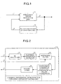
- Fig. 1 is a block diagram showing an example of a structure of a frequency error estimating apparatus relating to a first embodiment of the present invention
- Fig. 2 is a diagram showing an example of an internal structure of a frequency error estimating unit 11
- Fig. 3 is a diagram showing an example of an internal structure of an averaging filter 23
- Fig. 4 is a diagram showing an example of an internal structure of a filter coefficient determining unit 12
- Fig. 5 shows an example of a correspondence table
- Fig. 6 is a block diagram showing an example of a structure of a frequency error estimating apparatus relating to a second embodiment of the present invention
- Fig. 1 is a block diagram showing an example of a structure of a frequency error estimating apparatus relating to a first embodiment of the present invention
- Fig. 2 is a diagram showing an example of an internal structure of a frequency error estimating unit 11
- Fig. 3 is a diagram showing an example of an internal structure of an averaging filter 23
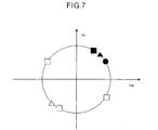
- FIG. 7 shows a method of selecting a frequency error estimated by a plurality of D-symbol differential detection type frequency error estimating units
- Fig. 8 is a diagram showing a structure of a conventional frequency error estimating apparatus
- Fig. 9 is a diagram showing an example of an internal structure of a conventional averaging filter.
- Fig. 1 is a block diagram showing an example of a structure of a frequency error estimating apparatus relating to a first embodiment of the present invention.
- legend 1 denotes a received signal
- legend 11 denotes a frequency error estimating unit for estimating a frequency error or differential between a local oscillation frequency and a carrier frequency of the received signal.
- Legend 2 denotes an estimated frequency error value
- legend 12 denotes a filter coefficient determining unit for calculating filter coefficient information of the averaging filter included in the frequency error estimating unit 11 based on the estimated frequency error value
- legend 3 denotes the filter coefficient information.
- Fig. 2 is a diagram showing an example of an internal structure of the frequency error estimating unit 11.
- This figure shows an example of a D-symbol differential detection type frequency error estimating unit 11a.
- items that are similar to those explained in the above prior-art technique are provided with same legends, and their explanation will be omitted.
- the D-symbol differential detection type frequency error estimating unit lla shown in Fig. 2 is based on a principle similar to that of the D-symbol differential detection type frequency error estimating unit explained in the above prior-art technique.
- the D-symbol differential detection type frequency error estimating unit lla is different from the conventional D-symbol differential detection type frequency error estimating unit in that the filter coefficient information 3 is input to the averaging filter 23, and that the filter characteristics of the averaging filter 23 change based on the filter coefficient information 3.
- Fig. 3 is a diagram showing an example of an internal structure of the averaging filter 23.
- This averaging filter 23 is a primary IIR filter similar to the averaging filter 101 explained in the above prior-art technique.
- the averaging filter 23 is different from the averaging filter 101 in that the filter coefficient information 3 is input to this averaging filter 23, and that multipliers 31 and 34 are provided in place of the multipliers 111 and 112, and the multiplier coefficients of the multipliers 31 and 34 change according to the filter coefficient information 3.
- Fig. 4 is a diagram showing an example of an internal structure of the filter coefficient determining unit 12.
- legend 41 denotes a differential arithmetic unit for calculating a differential of the estimated frequency error value 2
- legend 42 denotes an averaging filter for suppressing a noise component by averaging the output of the differential arithmetic unit 41
- Legend 43 denotes a coefficient determining unit for determining the filter coefficient information 3 based on the output of the averaging filter 42.
- the received signal 1 is input to the frequency error estimating apparatus 11, that is, the D-symbol differential detection type frequency error estimating unit 11a shown in Fig. 2.
- the D-symbol differential detection type frequency error estimating unit 11a that has received the received signal 1 operates in a similar manner to that of the D-symbol differential detection type frequency error estimating unit shown in Fig. 8 (corresponding to the equations (1) to (5)), and outputs the estimated frequency error value 2.
- the equation (5) is used for obtaining the output (d2(nT) of the averaging filter 23.
- the multiplier coefficient ⁇ changes based on the filter coefficient information 3.
- the estimated frequency error value 2 changes in proportion to time (nT) .
- the absolute value of the variable A becomes large accordingly.
- the differential amplifier 41 calculates a differential of the estimated frequency error value ⁇ T from R symbols.
- the averaging filter 42 averages the output of the differential arithmetic unit 41, and suppresses a noise component.
- the averaging filter the primary IIR filter shown in Fig. 9, or a higher-order IIR filter or an FIR (finite impulse response) filter may be used. Further, as described above, it is assumed that there is no noise component in this case. Therefore, the output of the averaging filter 42 is held, and this can be expressed directly by the equation (8).
- the coefficient determining unit 43 determines the filter coefficient information 3 according to the value of the output ( ⁇ d) of the averaging filter 42.
- the filter coefficient information 3 is the multiplier coefficient ⁇ of the multiplier 31, and the multiplier coefficient of the multiplier 34 is set as 1- ⁇ .
- the coefficient determining unit 43 when a time variation in the Doppler frequency is slow, the absolute value of the variable A becomes small. Therefore, the absolute value of ⁇ d also becomes small. When a time variation in the Doppler frequency is fast, the absolute value of the variable A becomes large. Therefore, the absolute value of ⁇ d also becomes large. In other words, ⁇ d be comes a yardstick that shows a size of the time variation in the Doppler frequency. As explained above, when the absolute value of ⁇ d is smaller than a predetermined value, the coefficient determining unit 43 sets ⁇ to a value as small as possible.
- the coefficient determining unit 43 sets ⁇ to a value as large as possible. With this arrangement, it is possible to increase the averaging effect of the averaging filter 23 when the time variation in the Doppler frequency is slow. As a result, it is possible to estimate a frequency error in high precision. On the other hand, when the time variation in the Doppler frequency is fast, it is possible to estimate a frequency error in high precision by following this variation.
- a correspondence table is prepared that shows a relationship between the absolute value of ⁇ d and the multiplier coefficient ⁇ , as shown in Fig. 5.
- the values of the multiplier coefficients ⁇ in the correspondence table are determined in advance to take optimum values by a simulation using a calculator or something like that.
- the example of the correspondence table shown in Fig. 5 is for changing the multiplier coefficient ⁇ at four stages according to the values of ⁇ d. This relationship is 0 ⁇ W1 ⁇ W2 ⁇ W3.
- the correspondence table employs the four stages in this case, the number of stages is not limited to four. It is also possible to change the multiplier coefficient ⁇ at any optional number of stages, for example, two stages or above.
- the coefficient determining unit 43 can select the multiplier coefficient ⁇ according to the value of ⁇ d by referring to the correspondence table. With this arrangement, it is possible to select optimum ⁇ according to the time variation in the Doppler frequency. It is possible to update the multiplier coefficient ⁇ for each symbol. However, in consideration of the stability of the filter coefficient determining unit 12, it is preferable to update the multiplier coefficient based on a specific period by using a counter. As this period, it is preferable to use the convergence time of the frequency error estimating unit 11.
- the present embodiment it is possible to satisfy both the level of following the time variation in the Doppler frequency and the precision in estimating the frequency error, by changing the characteristics of the averaging filter for suppressing a noise component of the phase change information according to the size of the time variation in the Doppler frequency, regardless of the size of the time variation in the Doppler frequency.
- a frequency error estimating apparatus relating to a second embodiment of the present invention has a similar structure to that of the frequency error estimating apparatus in the first embodiment shown in Fig. 1, except that the internal structure of the frequency error estimating unit 11 is different.
- Fig. 6 is a block diagram showing an example of an internal structure of the frequency error estimating apparatus 11 in the present embodiment.
- This frequency error estimating apparatus 11 is, for example, a multiple open-loop frequency error estimating unit 11b.
- the multiple open-loop frequency error estimating unit 11b is used as the frequency error estimating apparatus 11. Based on this arrangement, it is possible to achieve higher estimate precision over a wider estimating range than it is possible to achieve in the first embodiment.
- the multiple open-loop frequency error estimating unit is described in detail in "A Multiple Open-Loop Frequency Estimation Based on Differential Detection for MPSK", IEICE Trans. Commun., Vol. E82-B, 1, pp. 136-144, Jan., 1999.
- legends 51a, 51b, ..., and 51c denote N D-symbol differential detection type frequency error estimating units provided in parallel.
- Each of these D-symbol differential detection type frequency error estimating units has a structure similar to that of the D-symbol differential detection type frequency error estimating unit 11a shown in Fig. 2.
- the D-symbol differential detection type frequency error estimating units 51a, 51b, ..., and 51c have mutually different delay wave symbol distances D1 to DN respectively, that correspond to the delay wave symbol distance D in the D-symbol differential detector 22.
- Legend 52 denotes a selector for selectively outputting an optimum estimated frequency error value (that is considered to be correct) based on estimated frequency error values that are output from the D-symbol differential detection type frequency error estimating units 51a, 51b, ..., and 51c.
- the received signal 1 is input to the frequency error estimating apparatus 11, that is, the multiple open-loop frequency error estimating unit 11b shown in Fig. 6.
- the multiple open-loop frequency error estimating unit 11b that has received the received signal 1 branches the input received signal 1 into N systems.
- the multiple open-loop frequency error estimating unit 11b then inputs the divided received signals to the D-symbol differential detection type frequency error estimating units 51a, 51b, ..., and 51c respectively that have mutually different differential detection symbol distances (D1 to DN) provided in parallel.
- Each of the D-symbol differential detection type frequency error estimating units carries out a differential detection based on a distance different from the other symbol distance, and estimates a frequency error.
- the differential detection symbol distances are set in the order of D1 ⁇ D2 ⁇ ... ⁇ DN.
- the estimate range of a frequency error becomes wide, but the estimate precision becomes low.
- the estimate precision becomes high.
- a plurality of D-symbol differential detection type frequency error estimating units are laid out in parallel, starting from the D-symbol differential detection type frequency error estimating unit 51a that has a shortest differential detection symbol distance to the D-symbol differential detection type frequency error estimating unit 51c that has a longest differential detection symbol distance. Further, the selector 52 selects an output from the outputs of these D-symbol differential detection type frequency error estimating units. Based on this arrangement, it is possible to achieve high estimate precision over a wide estimate range.
- candidates of estimate values for the three D-symbol differential detection type frequency error estimating units become one ( ⁇ ), two ( ⁇ ), and four ( ⁇ ) that correspond to the respective differential detection symbol distance as shown in Fig. 7.
- the selector 52 first selects ⁇ (a black triangle in the drawing) that is closest to ⁇ from the two candidates ( ⁇ ). Next, the selector 52 selects ⁇ (a black square in the drawing) that is closest to ⁇ that has been selected previously from the four candidates ( ⁇ ). Then, the multiple open-loop frequency error estimating unit 11b outputs the selected ⁇ as the estimate value of the frequency error.
- the multiple open-loop frequency error estimating unit 11b operates while eliminating the uncertainty in the frequency. Therefore, the D- (D1) symbol differential detection type frequency error estimating unit 51a determines the estimating range of a frequency error, and the D- (DN) symbol differential detection type frequency error estimating unit 51c determines the estimate precision. In other words, based on the multiple open-loop frequency error estimating unit 11b of the present embodiment, it is possible to achieve both the wide estimating range and high estimate precision at the same time.
- the multiplier coefficient ⁇ of the averaging filter 23 in each D-symbol differential detection type frequency error estimating unit changes based on the filter coefficient information 3.
- the filter coefficient determining unit 12 determines the filter coefficient information 3 based on the differential between the estimated frequency error values, in a similar manner to that of the first embodiment.
- the present embodiment like in the above-explained first embodiment, it is possible to satisfy both the level of following the time variation in the Doppler frequency and the precision in estimating the frequency error, by changing the characteristics of the averaging filter for suppressing a noise component of the phase change information according to the size of the time variation in the Doppler frequency, regardless of the size of the time variation in the Doppler frequency. Further, by using the multiple open-loop frequency error estimating unit 11b that has a plurality of the D-symbol differential detection type frequency error estimating units laid out in parallel, it is possible to achieve both higher estimate precision and a wider estimating range at the same time.
- the filter coefficient when the time variation in the Doppler frequency is slow, the filter coefficient is set to a value as small as possible, and when the time variation in the Doppler frequency is fast, the filter coefficient is set to a value as large as possible.
- the frequency error estimating unit estimates a frequency error based on this filter coefficient.
- the frequency error estimating apparatus operates while eliminating the uncertainty in the frequency by selecting an optimum frequency error. Therefore, the differential detection type frequency error estimating unit with a shortest distance of a differential detection symbol determines an estimating range of a frequency error. Then, the differential detection type frequency error estimating unit with a longest distance of a differential detection symbol determines the estimate precision. With this arrangement, there is an effect that it is possible to achieve both the wide estimating range and high estimate precision at the same time.
- a correspondence table that relates differential values between estimate values of the frequency error to the filter coefficients.
- the values of the multiplier coefficients in the correspondence table are determined in advance to take optimum values by a simulation using a calculator or something like that.
- the updating is carried out in a specific period by using a counter in this case.
- the filter coefficient when the time variation in the Doppler frequency is slow, the filter coefficient is set to a value as small as possible, and when the time variation in the Doppler frequency is fast, the filter coefficient is set to a value as large as possible.
- a frequency error is estimated based on this filter coefficient.
- the operation is carried out while eliminating the uncertainty in the frequency by selecting an optimum frequency error. Therefore, an estimating range of a frequency error is determined at the seventh step when a distance of a differential detection symbol is shortest. Then, the estimate precision is determined at the seventh step when a distance of a differential detection symbol is longest. With this arrangement, there is an effect that it is possible to achieve both the wide estimating range and high estimate precision at the same time.
- a correspondence table that relates differential values between estimate values of the frequency error to the filter coefficients.
- the values of the multiplier coefficients in the correspondence table are determined in advance to take optimum values by a simulation using a calculator or something like that.
- the updating is carried out in a specific period by using a counter in this case.
- the frequency error estimating apparatus and the frequency error estimating method relating to the present invention are useful for estimating a frequency error or a frequency differential between a local oscillation frequency and a carrier frequency of a received signal in a receiver used for a satellite communication, a mobile satellite communication and a mobile communication.
- the frequency error estimating apparatus and the frequency error estimating method relating to the present invention are suitable for securing high precision in estimating a frequency error without losing the level of following the time variation in the Doppler frequency.
Landscapes
- Engineering & Computer Science (AREA)
- Computer Networks & Wireless Communication (AREA)
- Signal Processing (AREA)
- Digital Transmission Methods That Use Modulated Carrier Waves (AREA)
- Circuits Of Receivers In General (AREA)
- Channel Selection Circuits, Automatic Tuning Circuits (AREA)
- Cable Transmission Systems, Equalization Of Radio And Reduction Of Echo (AREA)
- Noise Elimination (AREA)
Abstract
A frequency error estimating apparatus for estimating
a frequency error between a local oscillation frequency and
a carrier frequency of a received signal in a receiver
includes a frequency error estimating unit (11) that
suppresses a noise component included in the received signal
according to a filter coefficient input to an averaging
filter (23), and estimates a frequency error based on an
output of the filter; and a filter coefficient determining
unit (12) that calculates a filter coefficient based on a
differential of estimate values of the frequency error from
a first symbol, and changes the characteristics of the filter .
In the receiver, the frequency error estimating apparatus
can secure high precision in estimating a frequency error
without losing the level of following the time variation
in the Doppler frequency.
Description
The present invention relates to a frequency error
estimating apparatus for estimating a frequency error or
a frequency differential between a local oscillation
frequency and a carrier frequency of a received signal in
a receiver used for a satellite communication, a mobile
satellite communication and a mobile communication. The
invention particularly relates to a frequency error
estimating apparatus capable of securing high precision in
estimating a frequency error without losing the level of
following the time variation in the Doppler frequency.
A conventional frequency error estimating apparatus
will be explained below. Some of the receivers used for
mobile communications employ a synchronous detection system
that is capable of obtaining satisfactory detection
characteristics even in a low C/N channel. According to
this synchronous detection system, a carrier that is
synchronous with a carrier frequency of a received signal
is reproduced, and a detection output is obtained based on
this carrier. However, the receiver that employs the
synchronous detection system has variations in the
oscillation frequency due to variations in the precision
of the oscillator, variations in temperature, etc. As a
result, there arises a difference in the frequency between
the transmitter and the receiver. In other words, a
frequency error occurs between the transmitter and the
receiver. When such a frequency error exists, the phase
at a signal point on an IQ plane (a complex plane expressed
by a real axis and an imaginary axis) rotates.
Therefore, in order to minimize this frequency error
and to improve the synchronous characteristics in the
receiver, it becomes necessary to provide a frequency error
estimating apparatus that measures a phase rotation volume
from a received signal and estimates a frequency error from
a result of this measurement.
Fig. 8 shows a structure of a conventional frequency
error estimating apparatus. This frequency error
estimating apparatus is disclosed in "Doppler-Corrected
Differential Detection of MPSK", IEEE Trans. Commun., Vol.
COM-37, 2, pp. 99-109, Feb., 1989. In Fig. 8, legend 1
denotes a received signal, legend 21 denotes an M-multiplier
for removing a modulation component of the received signal
1, and legend 22 denotes a D-symbol differential detector
for performing differential detection over a period of D
symbols based on the output of the M-multiplier 21. Legend
101 denotes an averaging filter for averaging the output
of the D-symbol differential detector 22, and thereby
suppressing a noise component. Legend 24 denotes a
coordinate converter for calculating a phase component from
the output of the averaging filter 101, and legend 25 denotes
a divider for calculating a frequency error from a phase
component that has been output from the coordinate converter
24. Legend 2 denotes an estimated frequency error value
that is output from the divider 25.
Fig. 9 shows an example of an internal structure of
the averaging filter 101. This shows an IIR (a primary
infinite impulse response) filter. In Fig. 9, legends 111
and 112 denote multipliers for multiplying an input signal
by a specific coefficient respectively. Legend 32 denotes
an adder for adding two inputs, and 33 denotes a delay unit
for delaying a signal by one symbol.
The conventional frequency error estimating apparatus
having the above-described structure is a D-symbol
differential detection type frequency error estimating
apparatus that estimates a phase change volume due to a
frequency error, by performing differential detection over
a period of D symbols based on a received signal.
The operation principle of the conventional frequency
error estimating apparatus will be explained with reference
to Fig. 8 and Fig. 9. When a modulation system used is the
M-phase PSK (phase shift keying) system, the received signal
1 (r(nT)) is expressed by the following equation (1).
r(nT) = A(nT) exp [j {(nT) + ΔωnT}]
In the equation (1), the received signal 1 (r(nT))
is a complex base band signal sampled in a symbol period
T. A(nT) expresses an amplitude component, and Δω expresses
an angular frequency error. (nT) expresses a modulation
component, and this takes M values of, for example, 2πk/M
(k = 0, 1, ..., and M - 1). To simplify the explanation,
it is assumed that there is no noise component.
The M-multiplier 21 multiplies the received signal
1 by a modulation multiple number M for removing the
modulation component of the received signal 1. A signal
after the multiplication (r1(nT)) is expressed by the
following equation (2).
r1(nT) = A(nT) exp [jM {(nT) + ΔωnT}]
In the equation (2), M(nT) is a multiple of 2π, and
therefore, this can be disregarded. The equation (2) can
be substituted by the following equation (3).
r1(nT) = A(nT) exp (jMΔωnT)
The D-symbol differential detector 22 performs
differential detection over a period of D symbols based on
the output (r1(n)) from the M-multiplier 21. A signal after
the differential detection (d1(nT)) is expressed by the
following equation (4).
d1 (nT) = r1(nt) r1 * (nT - DT)
= A (nT) A (nT -DT) exp (jMDΔωT)
In the equation (4), r1 * (nT - DT) is a conjugate
complex number of r1 (nT - DT).
The averaging filter 101 averages the output (d1(nT))
of the D-symbol differential detector 22, and thereby
suppresses the noise component. For example, when the
primary IIR filter shown in Fig. 9 is used as the averaging
filter, an output (d2(nT)) of the averaging filter 101 is
expressed by the following equation (5).
d2 (nT) = αd1 (nT) + (1-α) d2 (nT-T)
In the equation (5), the first term is a result of
the multiplier 111 multiplying the input signal (d1(nT))
by the coefficient α, and the second term is a result of
the multiplier 112 multiplying the one symbol-delayed output
(d2(nT-T)) of the averaging filter 101 by the coefficient
1-α.
When it is assumed that the sampling timing is a Nyquist
point, that is, when the amplitude component is assumed as
1, the output (d2(nT)) of the averaging filter 101 is
expressed by the following equation (6).
d2 (nT) = exp (jMDΔωT)
The coordinate converter 24 converts the output
(d2(nT)) of the averaging filter 101 from a Cartesian
coordinate into a polar coordinate, and calculates the phase
component (MDΔωT). Last, the divider 25 divides the phase
component (MDΔωT) that is the output of the coordinate
converter 24 by MD, thereby to calculate the angular
frequency error (ΔωT) over one symbol, and outputs a
calculated result.
According to the above-described conventional
frequency error estimating apparatus, however, in order to
estimate a frequency error in high precision, it is necessary
to set the coefficient α of the multiplier in the averaging
filter to a value as small as possible for increasing the
averaging effect. On the other hand, when the received
signal receives a large Doppler shift and the Doppler
frequency further varies with time like in the mobile
communication satellite, it is necessary that the frequency
error estimating apparatus follows this variation and
estimates the frequency error. In other words, in order
to increase this level of following the time variation in
the Doppler frequency, it is necessary to set the coefficient
α of the multiplier in the averaging filter to a value as
large as possible.
As the coefficient α of the multiplier has been fixed
in the conventional frequency error estimating apparatus,
there has been a problem that it is difficult to satisfy
both increasing the precision in estimating the frequency
error and increasing the level of following the time
variation in the Doppler frequency of the variation in the
Doppler frequency.
It is an object of the present invention to provide
a frequency error estimating apparatus and a frequency error
estimating method capable of securing high precision in
estimating the frequency error in a receiver, without losing
the level of following the time variation in the Doppler
frequency.
In order to achieve the above object, according to
a first aspect of the present invention, there is provided
a frequency error estimating apparatus for estimating a
frequency error between a local oscillation frequency and
a carrier frequency of a received signal in a receiver, the
frequency error estimating apparatus comprising: frequency
error estimating unit (corresponding to a frequency error
estimating unit 11 in an embodiment to be described later)
that suppresses a noise component included in the received
signal according to a filter coefficient input to a filter,
and estimates a frequency error based on an output of the
filter; and filter coefficient determining unit
(corresponding to a filter coefficient determining unit 12)
that calculates a filter coefficient based on a differential
of estimate values of the frequency error from a first symbol,
and changes the characteristics of the filter.
According to the above aspect, it is possible to satisfy
both the level of following the time variation in the Doppler
frequency and the precision in estimating the frequency error,
by changing the characteristics of a filter for suppressing
a noise component of a received signal according to the size
of the time variation in the Doppler frequency.
Further, according to a second aspect of the invention,
there is provided a frequency error estimating apparatus
of the above aspect, wherein the frequency error estimating
unit comprises: a modulation component removing unit
(corresponding to an M-multiplier 21) that removes a
modulation component from the received signal; a phase change
information generating unit (corresponding to a D-symbol
differential detector 22) that generates phase change
information by performing differential detection over a
period of a second symbol based on a signal after removing
a variation component, an averaging filter unit
(corresponding to an averaging filter 23) that suppresses
a noise component in the phase change information based on
the filter coefficient; and a frequency error estimating
unit (corresponding to a coordinate converter 24 and a
divider 25) that calculates a frequency error estimate value
based on a signal after suppressing the noise component.
According to the above aspect, when the time variation
in the Doppler frequency is slow, the filter coefficient
is set to a value as small as possible, and when the time
variation in the Doppler frequency is fast, the filter
coefficient is set to a value as large as possible. The
frequency error estimating unit estimates a frequency error
based on this filter coefficient. With this arrangement,
when the time variation in the Doppler frequency is slow,
the filter averaging effect is increased, and it is possible
to estimate the frequency error in high precision. On the
other hand, when the time variation in the Doppler frequency
is fast, it is possible to estimate the frequency error in
high precision by following this variation.
Further, according to a third aspect of the invention,
there is provided a frequency error estimating apparatus
of the above aspect, wherein the frequency error estimating
unit comprises: a plurality of differential detection type
frequency error estimating units (corresponding to D-symbol
differential detection type frequency error estimating
units 51a, 51b, ..., and 51c) that generate phase change
information by performing differential detection over
periods of predetermined symbols based on a received signal
after removing a modulation component, then suppress a noise
component in the phase change information based on the filter
coefficient, and thereafter estimate a frequency error based
on a signal after suppressing the noise component; and a
selecting unit (corresponding to a selector 52) that selects
an optimum frequency error, based on a predetermined standard,
from a plurality of frequency errors that have been estimated
by the plurality of differential detection type frequency
error estimating unit after performing differential
detection over different periods of symbols based on received
signals.
According to the above aspect, the frequency error
estimating apparatus operates while eliminating the
uncertainty in the frequency by selecting an optimum
frequency error. Therefore, the differential detection
type frequency error estimating unit with a shortest distance
of a differential detection symbol determines an estimating
range of a frequency error. Then, the differential
detection type frequency error estimating unit with a longest
distance of a differential detection symbol determines the
estimate precision. With this arrangement, it is possible
to achieve both the wide estimating range and high estimate
precision at the same time.
Further, according to a fourth aspect of the invention,
there is provided a frequency error estimating apparatus
of the above aspect, wherein the filter coefficient
determining unit includes in advance a correspondence table
that relates differential values between estimate values
of the frequency error to the filter coefficients, whereby,
after calculating a differential value, the filter
coefficient determining unit, selects a filter coefficient
corresponding to the differential value from the
correspondence table, and changes the characteristics of
the filter according to the value of the selected filter
coefficient.
According to the above aspect, there is prepared in
advance a correspondence table that relates differential
values between estimate values of the frequency error to
the filter coefficients. The values of the multiplier
coefficients in the correspondence table are determined in
advance to take optimum values by a simulation using a
calculator or something like that. With this arrangement,
it is possible to select easily a filter coefficient
corresponding to a differential value by referring to the
correspondence table. As a result, it is possible to select
an optimum filter coefficient according to a time variation
in the Doppler frequency.
Further, according to a fifth aspect of the invention,
there is provided a frequency error estimating apparatus
of the above aspect, wherein the filter coefficient
determining unit further includes a counter of a specific
period, whereby the filter coefficient determining unit
updates the filter coefficient in a period determined by
the counter.
According to the above aspect, while it is possible
to update the filter coefficient for each symbol, the
updating is carried out in a specific period by using a counter
in this case. With this arrangement, it is possible to
improve easily the stability of the filter coefficient
determining unit.
Further, according to a sixth aspect of the invention,
there is provided a frequency error estimating method for
estimating a frequency error between a local oscillation
frequency and a carrier frequency of a received signal in
a receiver, the frequency error estimating method
comprising: a first step of suppressing a noise component
included in the received signal according to a filter
coefficient input to a filter, and estimating a frequency
error based on an output of the filter; and a second step
of calculating a filter coefficient based on a differential
of estimate values of the frequency error from a first symbol,
and changing the characteristics of the filter.
According to the above aspect, it is possible to satisfy
both the level of following the time variation in the Doppler
frequency and the precision in estimating the frequency error,
by changing the characteristics of a filter for suppressing
a noise component of a received signal according to the size
of the time variation in the Doppler frequency.
Further, according to a seventh aspect of the invention,
there is provided a frequency error estimating method of
the above aspect, wherein the first step comprises: a third
step of removing a modulation component from the received
signal; a fourth step of generating phase change information
by performing differential detection over a period of a
second symbol based on a signal after removing a variation
component, a fifth step of suppressing a noise component
in the phase change information based on the filter
coefficient; and a sixth step of calculating a frequency
error estimate value based on a signal after suppressing
the noise component.
According to the above aspect, when the time variation
in the Doppler frequency is slow, the filter coefficient
is set to a value as small as possible, and when the time
variation in the Doppler frequency is fast, the filter
coefficient is set to a value as large as possible. At the
first step, a frequency error is estimated based on this
filter coefficient. With this arrangement, when the time
variation in the Doppler frequency is slow, the filter
averaging effect is increased, and it is possible to estimate
the frequency error in high precision. On the other hand,
when the time variation in the Doppler frequency is fast,
it is possible to estimate the frequency error in high
precision by following this variation.
Further, according to an eighth aspect of the invention,
there is provided a frequency error estimating method of
the above aspect, wherein the first step comprises: a
plurality of seventh steps of generating phase change
information by performing differential detection over
periods of predetermined symbols based on a received signal
after removing a modulation component, then suppressing a
noise component in the phase change information based on
the filter coefficient, and thereafter estimating a
frequency error based on a signal after suppressing the noise
component; and an eighth step of selecting an optimum
frequency error, based on a predetermined standard, from
a plurality of frequency errors that have been estimated
by the plurality of seventh steps after performing
differential detection over different periods of symbols
based on received signals.
According to the above aspect, the operation is carried
out while eliminating the uncertainty in the frequency by
selecting an optimum frequency error. Therefore, an
estimating range of a frequency error is determined at the
seventh step when a distance of a differential detection
symbol is shortest. Then, the estimate precision is
determined at the seventh step when a distance of a
differential detection symbol is longest. With this
arrangement, it is possible to achieve both the wide
estimating range and high estimate precision at the same
time.
Further, according to a ninth aspect of the invention,
there is provided a frequency error estimating method of
the above aspect, wherein the second step comprises a ninth
step of preparing in advance a correspondence table that
relates differential values between estimate values of the
frequency error to the filter coefficients, whereby, after
calculating a differential value, a filter coefficient
corresponding to the differential value is selected from
the correspondence table, and the characteristics of the
filter are changed according to the value of the selected
filter coefficient.
According to the above aspect, there is prepared in
advance a correspondence table that relates differential
values between estimate values of the frequency error to
the filter coefficients. The values of the multiplier
coefficients in the correspondence table are determined in
advance to take optimum values by a simulation using a
calculator or something like that. With this arrangement,
it is possible to select easily a filter coefficient
corresponding to a differential value by referring to the
correspondence table. As a result, it is possible to select
an optimum filter coefficient according to a time variation
in the Doppler frequency.
Further, according to a tenth aspect of the invention,
there is provided a frequency error estimating method of
the above aspect, wherein the second step further comprises
a tenth step for counting in a specific period, whereby the
filter coefficient is updated in a period determined by the
counter.
According to the above aspect, while it is possible
to update the filter coefficient for each symbol, the
updating is carried out in a specific period by using a counter
in this case. With this arrangement, it is possible to
improve easily the stability of the filter coefficient
obtained at the second step.
Fig. 1 is a block diagram showing an example of a
structure of a frequency error estimating apparatus relating
to a first embodiment of the present invention; Fig. 2 is
a diagram showing an example of an internal structure of
a frequency error estimating unit 11; Fig. 3 is a diagram
showing an example of an internal structure of an averaging
filter 23; Fig. 4 is a diagram showing an example of an internal
structure of a filter coefficient determining unit 12; Fig.
5 shows an example of a correspondence table; Fig. 6 is a
block diagram showing an example of a structure of a frequency
error estimating apparatus relating to a second embodiment
of the present invention; Fig. 7 shows a method of selecting
a frequency error estimated by a plurality of D-symbol
differential detection type frequency error estimating
units; Fig. 8 is a diagram showing a structure of a
conventional frequency error estimating apparatus; Fig. 9
is a diagram showing an example of an internal structure
of a conventional averaging filter.
Preferred embodiments of the present invention will
be explained in detail below with reference to the attached
drawings.
Fig. 1 is a block diagram showing an example of a
structure of a frequency error estimating apparatus relating
to a first embodiment of the present invention. In Fig.
1, legend 1 denotes a received signal, and legend 11 denotes
a frequency error estimating unit for estimating a frequency
error or differential between a local oscillation frequency
and a carrier frequency of the received signal. Legend 2
denotes an estimated frequency error value, legend 12 denotes
a filter coefficient determining unit for calculating filter
coefficient information of the averaging filter included
in the frequency error estimating unit 11 based on the
estimated frequency error value 2, and legend 3 denotes the
filter coefficient information.
Fig. 2 is a diagram showing an example of an internal
structure of the frequency error estimating unit 11. This
figure shows an example of a D-symbol differential detection
type frequency error estimating unit 11a. In the present
embodiment, items that are similar to those explained in
the above prior-art technique are provided with same legends,
and their explanation will be omitted. The D-symbol
differential detection type frequency error estimating unit
lla shown in Fig. 2 is based on a principle similar to that
of the D-symbol differential detection type frequency error
estimating unit explained in the above prior-art technique.
The D-symbol differential detection type frequency error
estimating unit lla is different from the conventional
D-symbol differential detection type frequency error
estimating unit in that the filter coefficient information
3 is input to the averaging filter 23, and that the filter
characteristics of the averaging filter 23 change based on
the filter coefficient information 3.
Fig. 3 is a diagram showing an example of an internal
structure of the averaging filter 23. This averaging filter
23 is a primary IIR filter similar to the averaging filter
101 explained in the above prior-art technique. The
averaging filter 23 is different from the averaging filter
101 in that the filter coefficient information 3 is input
to this averaging filter 23, and that multipliers 31 and
34 are provided in place of the multipliers 111 and 112,
and the multiplier coefficients of the multipliers 31 and
34 change according to the filter coefficient information
3.
Fig. 4 is a diagram showing an example of an internal
structure of the filter coefficient determining unit 12.
In Fig. 4, legend 41 denotes a differential arithmetic unit
for calculating a differential of the estimated frequency
error value 2, and legend 42 denotes an averaging filter
for suppressing a noise component by averaging the output
of the differential arithmetic unit 41. Legend 43 denotes
a coefficient determining unit for determining the filter
coefficient information 3 based on the output of the
averaging filter 42.
The operation of the frequency error estimating
apparatus will be explained next. First, the received
signal 1 is input to the frequency error estimating apparatus
11, that is, the D-symbol differential detection type
frequency error estimating unit 11a shown in Fig. 2. The
D-symbol differential detection type frequency error
estimating unit 11a that has received the received signal
1 operates in a similar manner to that of the D-symbol
differential detection type frequency error estimating unit
shown in Fig. 8 (corresponding to the equations (1) to (5)),
and outputs the estimated frequency error value 2. For
obtaining the output (d2(nT)) of the averaging filter 23,
the equation (5) is used. The multiplier coefficient α
changes based on the filter coefficient information 3.
The operation of the filter coefficient determining
unit 12 that calculates the filter coefficient information
3 will be explained next. It is assumed that a frequency
error changes in proportion to time based on a time variation
in the Doppler frequency. It is also assumed that the
estimated frequency error value 2 output by the frequency
error estimating unit 11 is an optimum (correct) value.
Therefore, the estimated frequency error value 2 is output
as an angular frequency error (ΔωT) from one symbol, and
this is expressed by the following equation (7).
ΔωT = AnT + B
As explained above, the estimated frequency error
value 2 changes in proportion to time (nT) . In other words,
when the time variation in the Doppler frequency becomes
fast, the absolute value of the variable A becomes large
accordingly.
The differential amplifier 41 calculates a
differential of the estimated frequency error value ΔωT from
R symbols. In the present embodiment, the output (Δωd) of
the differential amplifier 41 is expressed by the following
equation (8).
Δωd = ART
The averaging filter 42 averages the output of the
differential arithmetic unit 41, and suppresses a noise
component. As the averaging filter, the primary IIR filter
shown in Fig. 9, or a higher-order IIR filter or an FIR (finite
impulse response) filter may be used. Further, as described
above, it is assumed that there is no noise component in
this case. Therefore, the output of the averaging filter
42 is held, and this can be expressed directly by the equation
(8).
The coefficient determining unit 43 determines the
filter coefficient information 3 according to the value of
the output (Δωd) of the averaging filter 42. For example,
the filter coefficient information 3 is the multiplier
coefficient α of the multiplier 31, and the multiplier
coefficient of the multiplier 34 is set as 1-α.
Specifically, in the coefficient determining unit 43,
when a time variation in the Doppler frequency is slow, the
absolute value of the variable A becomes small. Therefore,
the absolute value of Δωd also becomes small. When a time
variation in the Doppler frequency is fast, the absolute
value of the variable A becomes large. Therefore, the
absolute value of Δωd also becomes large. In other words,
Δωd be comes a yardstick that shows a size of the time variation
in the Doppler frequency. As explained above, when the
absolute value of Δωd is smaller than a predetermined value,
the coefficient determining unit 43 sets α to a value as
small as possible. On the other hand, when the absolute
value of Δωd is larger than a predetermined value, the
coefficient determining unit 43 sets α to a value as large
as possible. With this arrangement, it is possible to
increase the averaging effect of the averaging filter 23
when the time variation in the Doppler frequency is slow.
As a result, it is possible to estimate a frequency error
in high precision. On the other hand, when the time variation
in the Doppler frequency is fast, it is possible to estimate
a frequency error in high precision by following this
variation.
In the present embodiment, as an example of a method
of determining the multiplier coefficient α, a
correspondence table is prepared that shows a relationship
between the absolute value of Δωd and the multiplier
coefficient α, as shown in Fig. 5. The values of the
multiplier coefficients α in the correspondence table are
determined in advance to take optimum values by a simulation
using a calculator or something like that. The example of
the correspondence table shown in Fig. 5 is for changing
the multiplier coefficient α at four stages according to
the values of Δωd. This relationship is 0 < W1 < W2 < W3.
Although the correspondence table employs the four stages
in this case, the number of stages is not limited to four.
It is also possible to change the multiplier coefficient
α at any optional number of stages, for example, two stages
or above.
Therefore, the coefficient determining unit 43 can
select the multiplier coefficient α according to the value
of Δωd by referring to the correspondence table. With this
arrangement, it is possible to select optimum α according
to the time variation in the Doppler frequency. It is
possible to update the multiplier coefficient α for each
symbol. However, in consideration of the stability of the
filter coefficient determining unit 12, it is preferable
to update the multiplier coefficient based on a specific
period by using a counter. As this period, it is preferable
to use the convergence time of the frequency error estimating
unit 11.
As explained above, according to the present
embodiment, it is possible to satisfy both the level of
following the time variation in the Doppler frequency and
the precision in estimating the frequency error, by changing
the characteristics of the averaging filter for suppressing
a noise component of the phase change information according
to the size of the time variation in the Doppler frequency,
regardless of the size of the time variation in the Doppler
frequency.
A frequency error estimating apparatus relating to
a second embodiment of the present invention has a similar
structure to that of the frequency error estimating apparatus
in the first embodiment shown in Fig. 1, except that the
internal structure of the frequency error estimating unit
11 is different. Fig. 6 is a block diagram showing an example
of an internal structure of the frequency error estimating
apparatus 11 in the present embodiment. This frequency
error estimating apparatus 11 is, for example, a multiple
open-loop frequency error estimating unit 11b.
In the present embodiment, the multiple open-loop
frequency error estimating unit 11b is used as the frequency
error estimating apparatus 11. Based on this arrangement,
it is possible to achieve higher estimate precision over
a wider estimating range than it is possible to achieve in
the first embodiment. The multiple open-loop frequency
error estimating unit is described in detail in "A Multiple
Open-Loop Frequency Estimation Based on Differential
Detection for MPSK", IEICE Trans. Commun., Vol. E82-B, 1,
pp. 136-144, Jan., 1999.
In Fig. 6, legends 51a, 51b, ..., and 51c denote N
D-symbol differential detection type frequency error
estimating units provided in parallel. Each of these
D-symbol differential detection type frequency error
estimating units has a structure similar to that of the
D-symbol differential detection type frequency error
estimating unit 11a shown in Fig. 2. The D-symbol
differential detection type frequency error estimating
units 51a, 51b, ..., and 51c have mutually different delay
wave symbol distances D1 to DN respectively, that correspond
to the delay wave symbol distance D in the D-symbol
differential detector 22. Legend 52 denotes a selector for
selectively outputting an optimum estimated frequency error
value (that is considered to be correct) based on estimated
frequency error values that are output from the D-symbol
differential detection type frequency error estimating
units 51a, 51b, ..., and 51c.
The operation of the frequency error estimating
apparatus in the present embodiment having the
above-described structure will be explained next. First,
the received signal 1 is input to the frequency error
estimating apparatus 11, that is, the multiple open-loop
frequency error estimating unit 11b shown in Fig. 6. The
multiple open-loop frequency error estimating unit 11b that
has received the received signal 1 branches the input
received signal 1 into N systems. The multiple open-loop
frequency error estimating unit 11b then inputs the divided
received signals to the D-symbol differential detection type
frequency error estimating units 51a, 51b, ..., and 51c
respectively that have mutually different differential
detection symbol distances (D1 to DN) provided in parallel.
Each of the D-symbol differential detection type
frequency error estimating units carries out a differential
detection based on a distance different from the other symbol
distance, and estimates a frequency error. The
differential detection symbol distances are set in the order
of D1 < D2 < ... < DN. In the present embodiment, when a
differential detection symbol distance is short, the
estimate range of a frequency error becomes wide, but the
estimate precision becomes low. On the other hand, when
a differential detection symbol distance is long, the
estimate range of a frequency error becomes narrow, but the
estimate precision becomes high. As explained above,
according to the multiple open-loop frequency error
estimating unit 11b of the present embodiment, a plurality
of D-symbol differential detection type frequency error
estimating units are laid out in parallel, starting from
the D-symbol differential detection type frequency error
estimating unit 51a that has a shortest differential
detection symbol distance to the D-symbol differential
detection type frequency error estimating unit 51c that has
a longest differential detection symbol distance. Further,
the selector 52 selects an output from the outputs of these
D-symbol differential detection type frequency error
estimating units. Based on this arrangement, it is possible
to achieve high estimate precision over a wide estimate
range.
As an example, the operation of the multiple open-loop
frequency error estimating unit consisting of three D-symbol
differential detection type frequency error estimating
units will be explained in detail below. In this multiple
open-loop frequency error estimating unit, a differential
detection symbol distance Di (where i = 1, 2, ..., and N)
is set as shown in the following equation (9).
Di = 2^ (i - 1) (i = 1, 2, 3)
In the equation (9), ^ expresses power.
Therefore, when an actual frequency error is π/4,
because of the uncertainty in the frequency, candidates of
estimate values for the three D-symbol differential
detection type frequency error estimating units become one
(○), two (Δ), and four (□) that correspond to the respective
differential detection symbol distance as shown in Fig. 7.
In this multiple open-loop frequency error estimating unit
11b, the selector 52 first selects ▵ (a black triangle in
the drawing) that is closest to ○ from the two candidates
(▵). Next, the selector 52 selects □ (a black square in
the drawing) that is closest to ▵ that has been selected
previously from the four candidates (□). Then, the multiple
open-loop frequency error estimating unit 11b outputs the
selected □ as the estimate value of the frequency error.
As explained above, the multiple open-loop frequency
error estimating unit 11b operates while eliminating the
uncertainty in the frequency. Therefore, the D- (D1) symbol
differential detection type frequency error estimating unit
51a determines the estimating range of a frequency error,
and the D- (DN) symbol differential detection type frequency
error estimating unit 51c determines the estimate precision.
In other words, based on the multiple open-loop frequency
error estimating unit 11b of the present embodiment, it is
possible to achieve both the wide estimating range and high
estimate precision at the same time.
Further, in the operation of the multiple open-loop
frequency error estimating unit 11b, the multiplier
coefficient α of the averaging filter 23 in each D-symbol
differential detection type frequency error estimating unit,
that is, α in the calculation equation of the averaging filter
23 shown in the equation (5), changes based on the filter
coefficient information 3. The filter coefficient
determining unit 12 determines the filter coefficient
information 3 based on the differential between the estimated
frequency error values, in a similar manner to that of the
first embodiment. With this arrangement, it is possible
to increase the averaging effect by setting α to a small
value when the time variation in the Doppler frequency is
slow. As a result, it is possible to estimate a frequency
error in high precision. On the other hand, when the time
variation in the Doppler frequency is fast, it is possible
to estimate a frequency error in high precision by setting
α to a large value and by following this variation. In the
present embodiment, it is also possible to use a
correspondence table as shown in Fig. 5 like in the first
embodiment.
As explained above, according to the present
embodiment, like in the above-explained first embodiment,
it is possible to satisfy both the level of following the
time variation in the Doppler frequency and the precision
in estimating the frequency error, by changing the
characteristics of the averaging filter for suppressing a
noise component of the phase change information according
to the size of the time variation in the Doppler frequency,
regardless of the size of the time variation in the Doppler
frequency. Further, by using the multiple open-loop
frequency error estimating unit 11b that has a plurality
of the D-symbol differential detection type frequency error
estimating units laid out in parallel, it is possible to
achieve both higher estimate precision and a wider estimating
range at the same time.
While the present invention has been explained with
reference to the first and second embodiments, it is possible
to modify the invention in various ways within the scope
of the gist of this invention. They are all included within
the range of the present invention.
As explained above, according to the present invention,
there is an effect that it is possible to obtain a frequency
error estimating apparatus capable of satisfying both the
level of following the time variation in the Doppler
frequency and the precision in estimating the frequency error,
by changing the characteristics of a filter for suppressing
a noise component of a received signal according to the size
of the time variation in the Doppler frequency.
Further, according to the present invention, when the
time variation in the Doppler frequency is slow, the filter
coefficient is set to a value as small as possible, and when
the time variation in the Doppler frequency is fast, the
filter coefficient is set to a value as large as possible.
The frequency error estimating unit estimates a frequency
error based on this filter coefficient. With this
arrangement, there is an effect that when the time variation
in the Doppler frequency is slow, the filter averaging effect
is increased, and it is possible to estimate the frequency
error in high precision. On the other hand, there is an
effect that when the time variation in the Doppler frequency
is fast, it is possible to estimate the frequency error in
high precision by following this variation.
Further, according to the present invention, the
frequency error estimating apparatus operates while
eliminating the uncertainty in the frequency by selecting
an optimum frequency error. Therefore, the differential
detection type frequency error estimating unit with a
shortest distance of a differential detection symbol
determines an estimating range of a frequency error. Then,
the differential detection type frequency error estimating
unit with a longest distance of a differential detection
symbol determines the estimate precision. With this
arrangement, there is an effect that it is possible to achieve
both the wide estimating range and high estimate precision
at the same time.
Further, according to the present invention, there
is prepared in advance a correspondence table that relates
differential values between estimate values of the frequency
error to the filter coefficients. The values of the
multiplier coefficients in the correspondence table are
determined in advance to take optimum values by a simulation
using a calculator or something like that. With this
arrangement, it is possible to select easily a filter
coefficient corresponding to a differential value by
referring to the correspondence table. As a result, there
is an effect that it is possible to select an optimum filter
coefficient according to a time variation in the Doppler
frequency.
Further, according to the present invention, while
it is possible to update the filter coefficient for each
symbol, the updating is carried out in a specific period
by using a counter in this case. With this arrangement,
there is an effect that it is possible to improve easily
the stability of the filter coefficient determining unit.
Further, according to the present invention, there
is an effect that it is possible to obtain a frequency error
estimating method that satisfies both the level of following
the time variation in the Doppler frequency and the precision
in estimating the frequency error, by changing the
characteristics of a filter for suppressing a noise component
of a received signal according to the size of the time
variation in the Doppler frequency.
Further, according to the present invention, when the
time variation in the Doppler frequency is slow, the filter
coefficient is set to a value as small as possible, and when
the time variation in the Doppler frequency is fast, the
filter coefficient is set to a value as large as possible.
At the first step, a frequency error is estimated based on
this filter coefficient. With this arrangement, there is
an effect that when the time variation in the Doppler
frequency is slow, the filter averaging effect is increased,
and it is possible to estimate the frequency error in high
precision. On the other hand, there is an effect that when
the time variation in the Doppler frequency is fast, it is
possible to estimate the frequency error in high precision
by following this variation.
Further, according to the present invention, the
operation is carried out while eliminating the uncertainty
in the frequency by selecting an optimum frequency error.
Therefore, an estimating range of a frequency error is
determined at the seventh step when a distance of a
differential detection symbol is shortest. Then, the
estimate precision is determined at the seventh step when
a distance of a differential detection symbol is longest.
With this arrangement, there is an effect that it is possible
to achieve both the wide estimating range and high estimate
precision at the same time.
Further, according to the present invention, there
is prepared in advance a correspondence table that relates
differential values between estimate values of the frequency
error to the filter coefficients. The values of the
multiplier coefficients in the correspondence table are
determined in advance to take optimum values by a simulation
using a calculator or something like that. With this
arrangement, it is possible to select easily a filter
coefficient corresponding to a differential value by
referring to the correspondence table. As a result, there
is an effect that it is possible to select an optimum filter
coefficient according to a time variation in the Doppler
frequency.
Further, according to the present invention, while
it is possible to update the filter coefficient for each
symbol, the updating is carried out in a specific period
by using a counter in this case. With this arrangement,
there is an effect that it is possible to improve easily
the stability of the filter coefficient obtained at the
second step.
The frequency error estimating apparatus and the
frequency error estimating method relating to the present
invention are useful for estimating a frequency error or
a frequency differential between a local oscillation
frequency and a carrier frequency of a received signal in
a receiver used for a satellite communication, a mobile
satellite communication and a mobile communication. The
frequency error estimating apparatus and the frequency error
estimating method relating to the present invention are
suitable for securing high precision in estimating a
frequency error without losing the level of following the
time variation in the Doppler frequency.
Claims (10)
- A frequency error estimating apparatus for estimating a frequency error between a local oscillation frequency and a carrier frequency of a received signal in a receiver, the frequency error estimating apparatus comprising:a frequency error estimating unit that suppresses a noise component included in the received signal according to a filter coefficient input to a filter, and estimates a frequency error based on an output of the filter; anda filter coefficient determining unit that calculates a filter coefficient based on a differential of estimate values of the frequency error from a first symbol, and changes the characteristics of the filter.
- The frequency error estimating apparatus according to claim 1, wherein the frequency error estimating unit includes,a modulation component removing unit that removes a modulation component from the received signal;a phase change information generating unit that generates phase change information by performing differential detection over a period of a second symbol based on a signal after removing a variation component,an averaging filter unit that suppresses a noise component in the phase change information based on the filter coefficient; anda frequency error estimating unit that calculates a frequency error estimate value based on a signal after suppressing the noise component.
- The frequency error estimating apparatus according to claim 1, the frequency error estimating unit includes,a plurality of differential detection type frequency error estimating units that generate phase change information by performing differential detection over periods of predetermined symbols based on a received signal after removing a modulation component, then suppress a noise component in the phase change information based on the filter coefficient, and thereafter estimate a frequency error based on a signal after suppressing the noise component; anda selecting unit that selects an optimum frequency error, based on a predetermined standard, from a plurality of frequency errors that have been estimated by the plurality of differential detection type frequency error estimating units after performing differential detection over different periods of symbols based on received signals.
- The frequency error estimating apparatus according to claim 1, wherein the filter coefficient determining unit includes in advance a correspondence table that relates differential values between estimate values of the frequency error to the filter coefficients, whereby, after calculating a differential value, the filter coefficient determining unit, selects a filter coefficient corresponding to the differential value from the correspondence table, and changes the characteristics of the filter according to the value of the selected filter coefficient.
- The frequency error estimating apparatus according to claim 4, wherein the filter coefficient determining unit further includes a counter of a specific period, whereby the filter coefficient determining unit updates the filter coefficient in a period determined by the counter.
- A frequency error estimating method for estimating a frequency error between a local oscillation frequency and a carrier frequency of a received signal in a receiver, the frequency error estimating method comprising:a first step of suppressing a noise component included in the received signal according to a filter coefficient input to a filter, and estimating a frequency error based on an output of the filter; anda second step of calculating a filter coefficient based on a differential of estimate values of the frequency error from a first symbol, and changing the characteristics of the filter.
- The frequency error estimating method according to claim 6, wherein the first step includes,a third step of removing a modulation component from the received signal;a fourth step of generating phase change information by performing differential detection over a period of a second symbol based on a signal after removing a variation component,a fifth step of suppressing a noise component in the phase change information based on the filter coefficient; anda sixth step of calculating a frequency error estimate value based on a signal after suppressing the noise component.
- The frequency error estimating method according to claim 6, wherein the first step includes,a plurality of seventh steps of generating phase change information by performing differential detection over periods of predetermined symbols based on a received signal after removing a modulation component, then suppressing a noise component in the phase change information based on the filter coefficient, and thereafter estimating a frequency error based on a signal after suppressing the noise component; andan eighth step of selecting an optimum frequency error, based on a predetermined standard, from a plurality of frequency errors that have been estimated by the plurality of seventh steps after performing differential detection over different periods of symbols based on received signals .
- The frequency error estimating method according to claim 6, wherein the second step includes a ninth step of preparing in advance a correspondence table that relates differential values between estimate values of the frequency error to the filter coefficients, whereby, after calculating a differential value, a filter coefficient corresponding to the differential value is selected from the correspondence table, and the characteristics of the filter are changed according to the value of the selected filter coefficient.
- The frequency error estimating method according to claim 9, wherein the second step includes a tenth step of counting in a specific period, whereby the filter coefficient is updated in a period determined by the counter.
Applications Claiming Priority (3)
| Application Number | Priority Date | Filing Date | Title |
|---|---|---|---|
| JP19314699 | 1999-07-07 | ||
| JP19314699A JP3190318B2 (en) | 1999-07-07 | 1999-07-07 | Frequency error estimating apparatus and frequency error estimating method |
| PCT/JP2000/004409 WO2001005110A1 (en) | 1999-07-07 | 2000-07-03 | Frequency error estimating device and frequency error estimating method |
Publications (2)
| Publication Number | Publication Date |
|---|---|
| EP1113636A1 true EP1113636A1 (en) | 2001-07-04 |
| EP1113636A4 EP1113636A4 (en) | 2006-02-01 |
Family
ID=16303060
Family Applications (1)
| Application Number | Title | Priority Date | Filing Date |
|---|---|---|---|
| EP00942450A Withdrawn EP1113636A4 (en) | 1999-07-07 | 2000-07-03 | DEVICE FOR ESTIMATING A FREQUENCY ERROR, AND METHOD FOR ESTIMATING A FREQUENCY ERROR |
Country Status (9)
| Country | Link |
|---|---|
| US (1) | US6674814B2 (en) |
| EP (1) | EP1113636A4 (en) |
| JP (1) | JP3190318B2 (en) |
| KR (1) | KR100404830B1 (en) |
| CN (1) | CN1316148A (en) |
| AU (1) | AU756256B2 (en) |
| CA (1) | CA2343064A1 (en) |
| TW (1) | TW472466B (en) |
| WO (1) | WO2001005110A1 (en) |
Cited By (1)
| Publication number | Priority date | Publication date | Assignee | Title |
|---|---|---|---|---|
| EP2133708A3 (en) * | 2008-06-09 | 2010-09-15 | Fujitsu Ltd. | Radio communication apparatus and frequency offset calculation method |
Families Citing this family (14)
| Publication number | Priority date | Publication date | Assignee | Title |
|---|---|---|---|---|
| US6778618B1 (en) * | 2000-08-16 | 2004-08-17 | Agere Systems, Inc. | Methods and devices for minimizing interblock interference in discrete multi-tone devices |
| JP2002152081A (en) * | 2000-11-07 | 2002-05-24 | Matsushita Electric Ind Co Ltd | Receiver and reference frequency control method in receiver |
| GB0126130D0 (en) * | 2001-10-31 | 2002-01-02 | Nokia Corp | Frequency error estimation |
| KR100845101B1 (en) * | 2002-01-22 | 2008-07-09 | 주식회사 팬택앤큐리텔 | Carrier Frequency Offset Compensator Using Various Frequency Offset Estimation Ranges |
| KR100522607B1 (en) * | 2003-07-15 | 2005-10-19 | 삼성전자주식회사 | Apparatus and method for executing adaptive video signal processing according to noise condition |
| KR100568069B1 (en) | 2004-09-02 | 2006-04-05 | 한국전자통신연구원 | Apparatus and Method for Estimating Carrier and Doppler Frequency Error in TMD Communication System |
| MX2007005453A (en) * | 2004-11-05 | 2007-05-21 | Interdigital Tech Corp | Adaptive equalizer with a dual-mode active taps mask generator and a pilot reference signal amplitude control unit. |
| US7457347B2 (en) * | 2004-11-08 | 2008-11-25 | Interdigital Technology Corporation | Method and apparatus for estimating and correcting baseband frequency error in a receiver |
| JP2007006105A (en) | 2005-06-23 | 2007-01-11 | Nec Corp | Radio base station and doppler frequency estimating method |
| KR100947604B1 (en) | 2007-12-17 | 2010-03-15 | 한국전자통신연구원 | Frequency Error Estimator Using Second-Order Loop Filter in Mobile Communication System and Its Operation Method |
| CN101998028B (en) * | 2009-08-13 | 2012-08-29 | 承景科技股份有限公司 | Carrier Tracking System and Method |
| RU2475953C1 (en) * | 2012-02-08 | 2013-02-20 | Закрытое акционерное общество "ИВЛА-ОПТ" | Pulse selector |
| US9059889B2 (en) * | 2013-03-11 | 2015-06-16 | Technion Research And Development Foundation Ltd. | Polar multi-symbol delay detector for carrier phase and frequency recovery for coherent transmission |
| JP6388754B1 (en) * | 2017-09-15 | 2018-09-12 | 三菱電機株式会社 | Signal processing device, sensor device, and signal processing method |
Family Cites Families (29)
| Publication number | Priority date | Publication date | Assignee | Title |
|---|---|---|---|---|
| FR2283606A1 (en) * | 1974-08-30 | 1976-03-26 | Stern Thomas | PHASE FILTER TO REDUCE THE EFFECTS OF NOISE COMPONENTS AFFECTING SIGNALS MODULATED IN PHASE BY DISCREET VALUES |
| CA2008595C (en) * | 1989-01-26 | 1995-03-07 | Nec Corporation | Coherent psk demodulator with adaptive line enhancer |
| JP2752692B2 (en) | 1989-04-21 | 1998-05-18 | 日本電気株式会社 | Phase modulation signal demodulator |
| JPH0770995B2 (en) * | 1989-03-14 | 1995-07-31 | 富士通株式会社 | Phase locked loop |
| JPH0722294B2 (en) | 1990-04-25 | 1995-03-08 | 日本電気株式会社 | Automatic frequency control method |
| CA2110881C (en) * | 1992-12-09 | 1998-07-28 | Kyo Takahashi | Adaptive equalizer capable of compensating for carrier frequency offset |
| JPH06188787A (en) | 1992-12-17 | 1994-07-08 | Japan Radio Co Ltd | Adaptive automatic equalizer |
| JPH06177801A (en) * | 1992-12-09 | 1994-06-24 | Japan Radio Co Ltd | Adaptive automatic equalizer |
| JPH06232926A (en) * | 1993-02-01 | 1994-08-19 | Sanyo Electric Co Ltd | Carrier signal reproducing circuit |
| JP2989732B2 (en) | 1993-08-23 | 1999-12-13 | エヌ・ティ・ティ移動通信網株式会社 | Frequency offset compensation circuit |
| US5481270A (en) * | 1994-03-04 | 1996-01-02 | Martin Marietta Corporation | Radar with adaptive range sidelobe suppression |
| KR0134280B1 (en) * | 1994-10-12 | 1998-04-27 | 김광호 | Digital Communication Receiver for Pulse Amplitude Modulated Signals |
| US5684836A (en) | 1994-12-22 | 1997-11-04 | Mitsubishi Denki Kabushiki Kaisha | Receiver with automatic frequency control |
| JP2806296B2 (en) | 1995-03-11 | 1998-09-30 | 日本電気株式会社 | Carrier recovery circuit |
| JP3200547B2 (en) * | 1995-09-11 | 2001-08-20 | 株式会社日立製作所 | CDMA mobile communication system |
| DE69619783T2 (en) * | 1995-12-28 | 2002-10-02 | Thomson Consumer Electronics, Inc. | Phase locked loop with adjustable response time |
| FI102338B1 (en) * | 1996-05-21 | 1998-11-13 | Nokia Mobile Phones Ltd | Recipient's self-synchronization in idle condition |
| KR100194937B1 (en) * | 1996-08-30 | 1999-06-15 | 윤종용 | Digital Signal Adaptive Decision Error Circuit and Method for Digital Modulation Modulation System |
| WO1998021847A1 (en) * | 1996-11-13 | 1998-05-22 | Nokia Telecommunications Oy | Method, transmitter and receiver for transmitting training signals in a tdma transmission system |
| US6072842A (en) * | 1996-11-21 | 2000-06-06 | Dsp Group, Inc. | Carrier-recovery loop with stored initialization in a radio receiver |
| JPH10210095A (en) | 1997-01-28 | 1998-08-07 | Toshiba Corp | Frequency error correction method and wireless communication device |
| AU723679B2 (en) * | 1997-03-04 | 2000-08-31 | Mitsubishi Denki Kabushiki Kaisha | Receiver with a frequency offset correcting function |
| GB2325126B (en) * | 1997-05-02 | 2002-06-19 | Lsi Logic Corp | Demodulating digital video broadcast signals |
| JPH10322259A (en) * | 1997-05-19 | 1998-12-04 | Matsushita Electric Ind Co Ltd | Digital cordless communication system |
| US6058101A (en) * | 1997-06-11 | 2000-05-02 | Industrial Technology Research Institute | Synchronization method and system for a digital receiver |
| CA2217840C (en) * | 1997-10-09 | 2005-05-03 | Northern Telecom Limited | Synchronization system multiple modes of operation |
| JP3659800B2 (en) * | 1998-04-15 | 2005-06-15 | 三菱電機株式会社 | Phase error detector |
| JP2000174677A (en) | 1998-12-04 | 2000-06-23 | Hitachi Denshi Ltd | Decryption method |
| WO2005097645A1 (en) | 2004-04-05 | 2005-10-20 | Koenig & Bauer Aktiengesellschaft | Method and devices for severing sheets from and/or feeding a web into a subsequent processing stage |
-
1999
- 1999-07-07 JP JP19314699A patent/JP3190318B2/en not_active Expired - Fee Related
-
2000
- 2000-07-03 AU AU57082/00A patent/AU756256B2/en not_active Ceased
- 2000-07-03 CN CN00801253A patent/CN1316148A/en active Pending
- 2000-07-03 CA CA002343064A patent/CA2343064A1/en not_active Abandoned
- 2000-07-03 TW TW089113135A patent/TW472466B/en not_active IP Right Cessation
- 2000-07-03 EP EP00942450A patent/EP1113636A4/en not_active Withdrawn
- 2000-07-03 WO PCT/JP2000/004409 patent/WO2001005110A1/en not_active Ceased
- 2000-07-03 KR KR10-2001-7002904A patent/KR100404830B1/en not_active Expired - Fee Related
-
2001
- 2001-03-06 US US09/798,900 patent/US6674814B2/en not_active Expired - Fee Related
Cited By (2)
| Publication number | Priority date | Publication date | Assignee | Title |
|---|---|---|---|---|
| EP2133708A3 (en) * | 2008-06-09 | 2010-09-15 | Fujitsu Ltd. | Radio communication apparatus and frequency offset calculation method |
| US8060051B2 (en) | 2008-06-09 | 2011-11-15 | Fujitsu Limited | Radio communication apparatus and frequency offset calculation method |
Also Published As
| Publication number | Publication date |
|---|---|
| US6674814B2 (en) | 2004-01-06 |
| WO2001005110A1 (en) | 2001-01-18 |
| JP2001024727A (en) | 2001-01-26 |
| TW472466B (en) | 2002-01-11 |
| AU756256B2 (en) | 2003-01-09 |
| CA2343064A1 (en) | 2001-01-18 |
| KR20010079752A (en) | 2001-08-22 |
| EP1113636A4 (en) | 2006-02-01 |
| CN1316148A (en) | 2001-10-03 |
| JP3190318B2 (en) | 2001-07-23 |
| US20010008543A1 (en) | 2001-07-19 |
| KR100404830B1 (en) | 2003-11-07 |
| AU5708200A (en) | 2001-01-30 |
Similar Documents
| Publication | Publication Date | Title |
|---|---|---|
| US6674814B2 (en) | Frequency error estimating apparatus and a frequency error estimating method | |
| EP1380122B1 (en) | Method and apparatus for estimating doppler spread | |
| JP3118548B2 (en) | Synchronous detection device and synchronization method for digital communication receiver | |
| US5936961A (en) | Signalling packet for communication system with reference modulated in accordance with a time-dependent law | |
| US5434889A (en) | Receiver comprising an arrangement for estimating a frequency deviation | |
| JP2006527952A (en) | Method and apparatus for estimating carrier frequency offset and fading rate using autoregressive channel modeling | |
| JPWO2000076165A1 (en) | Automatic Frequency Control Device | |
| JP2002530903A (en) | Frequency acquisition tracking method and apparatus for DS-SSCDMA receiver | |
| KR100567290B1 (en) | Method and apparatus for detecting frequency synchronization signal | |
| JP3910448B2 (en) | Automatic frequency control method and apparatus and demodulator | |
| JP3576420B2 (en) | Frequency offset correction device | |
| CA2224992C (en) | Carrier recovery for digitally phase modulated signals, using a known sequence | |
| EP1566906A1 (en) | Delay profile estimation device and correlator | |
| CN113037671A (en) | Low-complexity efficient SOQPSK symbol timing and phase joint synchronization algorithm | |
| US7620125B1 (en) | Frequency estimation apparatus and related method | |
| JP2003204293A (en) | Compensation transmission method for phasing distortion or frequency offset | |
| JP2000354077A (en) | Frequency error estimating apparatus and method | |
| EP0851640B1 (en) | Correction of DC and phase offsets in PSK receivers | |
| EP0999651B1 (en) | Channel characteristics estimation apparatus | |
| JP3103014B2 (en) | Receiving machine | |
| JP3501767B2 (en) | Frequency error estimating apparatus and frequency error estimating method | |
| CN114578284B (en) | Adjusting DFT coefficients to compensate for frequency offset during the probing sequence for fractional time determination | |
| KR20030003230A (en) | Correction of quadrature and gain errors in homodyne receives | |
| JP3512296B2 (en) | Fading equalizer | |
| JP2932380B1 (en) | Interference wave detection circuit |
Legal Events
| Date | Code | Title | Description |
|---|---|---|---|
| PUAI | Public reference made under article 153(3) epc to a published international application that has entered the european phase |
Free format text: ORIGINAL CODE: 0009012 |
|
| 17P | Request for examination filed |
Effective date: 20010301 |
|
| AK | Designated contracting states |
Kind code of ref document: A1 Designated state(s): AT BE CH CY DE DK ES FI FR GB GR IE IT LI LU MC NL PT SE |
|
| RBV | Designated contracting states (corrected) |
Designated state(s): DE FR GB IT |
|
| A4 | Supplementary search report drawn up and despatched |
Effective date: 20051219 |
|
| RAP1 | Party data changed (applicant data changed or rights of an application transferred) |
Owner name: MITSUBISHI DENKI KABUSHIKI KAISHA |
|
| STAA | Information on the status of an ep patent application or granted ep patent |
Free format text: STATUS: THE APPLICATION IS DEEMED TO BE WITHDRAWN |
|
| 18D | Application deemed to be withdrawn |
Effective date: 20060928 |