EP1113623A2 - Data transfer method using layer 2 signaling of protocol identifier, radio terminal and radio gateway device - Google Patents
Data transfer method using layer 2 signaling of protocol identifier, radio terminal and radio gateway device Download PDFInfo
- Publication number
- EP1113623A2 EP1113623A2 EP00311696A EP00311696A EP1113623A2 EP 1113623 A2 EP1113623 A2 EP 1113623A2 EP 00311696 A EP00311696 A EP 00311696A EP 00311696 A EP00311696 A EP 00311696A EP 1113623 A2 EP1113623 A2 EP 1113623A2
- Authority
- EP
- European Patent Office
- Prior art keywords
- radio
- gateway
- signaling
- radio terminal
- protocol
- Prior art date
- Legal status (The legal status is an assumption and is not a legal conclusion. Google has not performed a legal analysis and makes no representation as to the accuracy of the status listed.)
- Granted
Links
Images






Classifications
-
- H—ELECTRICITY
- H04—ELECTRIC COMMUNICATION TECHNIQUE
- H04L—TRANSMISSION OF DIGITAL INFORMATION, e.g. TELEGRAPHIC COMMUNICATION
- H04L12/00—Data switching networks
- H04L12/28—Data switching networks characterised by path configuration, e.g. LAN [Local Area Networks] or WAN [Wide Area Networks]
- H04L12/40—Bus networks
- H04L12/40052—High-speed IEEE 1394 serial bus
- H04L12/40117—Interconnection of audio or video/imaging devices
-
- H—ELECTRICITY
- H04—ELECTRIC COMMUNICATION TECHNIQUE
- H04L—TRANSMISSION OF DIGITAL INFORMATION, e.g. TELEGRAPHIC COMMUNICATION
- H04L12/00—Data switching networks
- H04L12/28—Data switching networks characterised by path configuration, e.g. LAN [Local Area Networks] or WAN [Wide Area Networks]
- H04L12/40—Bus networks
- H04L12/40052—High-speed IEEE 1394 serial bus
-
- H—ELECTRICITY
- H04—ELECTRIC COMMUNICATION TECHNIQUE
- H04L—TRANSMISSION OF DIGITAL INFORMATION, e.g. TELEGRAPHIC COMMUNICATION
- H04L12/00—Data switching networks
- H04L12/28—Data switching networks characterised by path configuration, e.g. LAN [Local Area Networks] or WAN [Wide Area Networks]
- H04L12/46—Interconnection of networks
- H04L12/4604—LAN interconnection over a backbone network, e.g. Internet, Frame Relay
- H04L12/462—LAN interconnection over a bridge based backbone
- H04L12/4625—Single bridge functionality, e.g. connection of two networks over a single bridge
-
- H—ELECTRICITY
- H04—ELECTRIC COMMUNICATION TECHNIQUE
- H04W—WIRELESS COMMUNICATION NETWORKS
- H04W76/00—Connection management
- H04W76/10—Connection setup
-
- H—ELECTRICITY
- H04—ELECTRIC COMMUNICATION TECHNIQUE
- H04W—WIRELESS COMMUNICATION NETWORKS
- H04W88/00—Devices specially adapted for wireless communication networks, e.g. terminals, base stations or access point devices
- H04W88/16—Gateway arrangements
-
- H—ELECTRICITY
- H04—ELECTRIC COMMUNICATION TECHNIQUE
- H04W—WIRELESS COMMUNICATION NETWORKS
- H04W92/00—Interfaces specially adapted for wireless communication networks
- H04W92/16—Interfaces between hierarchically similar devices
- H04W92/18—Interfaces between hierarchically similar devices between terminal devices
-
- H—ELECTRICITY
- H04—ELECTRIC COMMUNICATION TECHNIQUE
- H04W—WIRELESS COMMUNICATION NETWORKS
- H04W92/00—Interfaces specially adapted for wireless communication networks
- H04W92/16—Interfaces between hierarchically similar devices
- H04W92/24—Interfaces between hierarchically similar devices between backbone network devices
Definitions
- the present invention relates to a radio terminal belonging to a radio network for carrying out communications by setting up logical channels on a radio network in advance and an information transfer method of a radio terminal, as well as to a radio gateway device for connecting an IEEE 1394 bus with a radio network for carrying out communications by setting up logical channels on a radio network in advance and an information transfer method of a radio gateway device.
- the IEEE 1394 bus is capable of connecting a plurality of IEEE nodes in daisy chain or star connection and transferring a wideband data in excess of 100 Mbps. Also, it has a major feature that it is possible to transmit both asynchronous data and isochronous data on the same cable. For this reason, even though the IEEE 1394 bus was originally developed as a next generation version of SCSI, there are increasing trends to use the IEEE 1394 bus as a cable for connecting AV devices.
- one of the problems is how a protocol executed on the IEEE 1394 bus (a protocol presupposing the IEEE 1394 at the datalink layer such as AV/C protocol) can be executed over the radio network.
- a protocol such as the AV/C protocol in which message types (command, response, etc.) on the protocol are identified by logical addresses (registers) on the IEEE 1394 bus (where a value indicating an AV/C command or a value indicating an AV/C response can be found by reading a register according to an offset value described in a packet)
- identifiers corresponding to the logical addresses on that IEEE 1394 bus must also be provided at the radio LAN side. This situation is similar in the case of executing the AV/C protocol or the like between radio terminals.
- an information transfer method for transferring information regarding an AV control protocol in a radio system for carrying out data transfer after establishing a logical connection between radio terminals or gateways prior to data transfer between radio terminals or gateways, the method comprising the steps of: exchanging signaling packets for signaling at a datalink layer between the radio terminals or gateways prior to an exchange of data packets on which the information regarding the AV control protocol is loaded, each signaling packet containing a channel identifier indicating a logical channel that is set up for transferring the data packets and a protocol identifier indicating the AV control protocol, such that a signaling packet transmitted from each radio terminal or gateway indicates a channel identifier that is set up for the each radio terminal or gateway and a signaling packet received from a correspondent radio terminal or gateway indicates a channel identifier that is set up for the correspondent radio terminal or gateway; storing at the each radio terminal or gateway a correspondence information obtained through an exchange of the signaling packets, the correspondence information indicating
- an information transfer method for transferring information regarding an AV control protocol at a radio gateway connecting an IEEE 1394 bus with a radio network for carrying out data transfer after establishing a logical connection between radio terminals or gateways prior to data transfer between radio terminals or gateways, the method comprising the steps of: exchanging signaling packets for signaling at a datalink layer with a correspondent radio terminal or gateway on the radio network prior to an exchange of data packets on which the information regarding the AV control protocol is loaded, each signaling packet containing a channel identifier indicating a logical channel that is set up for transferring the data packets and a protocol identifier indicating the AV control protocol, such that a signaling packet transmitted from the radio gateway indicates a channel identifier that is set up for the radio gateway and a signaling packet received from the correspondent radio terminal or gateway indicates a channel identifier that is set up for the correspondent radio terminal or gateway; storing a correspondence information obtained through an exchange of the signaling packets, the correspondence information
- a radio terminal device in a radio system for carrying out data transfer after establishing a logical connection between radio terminals or gateways prior to data transfer between radio terminals or gateways
- the radio terminal device comprising: a signaling packet exchange unit configured to exchange signaling packets for signaling at a datalink layer with a correspondent radio terminal or gateway prior to an exchange of data packets on which the information regarding the AV control protocol is loaded, each signaling packet containing a channel identifier indicating a logical channel that is set up for transferring the data packets and a protocol identifier indicating the AV control protocol, such that a signaling packet transmitted from the radio terminal device indicates a channel identifier that is set up for the radio terminal device and a signaling packet received from the correspondent radio terminal or gateway indicates a channel identifier that is set up for the correspondent radio terminal or gateway; a memory unit configured to store a correspondence information obtained through an exchange of the signaling packets, the correspondence information indicating a correspondence among the protocol identifier
- a radio gateway device connecting an IEEE 1394 bus with a radio network for carrying out data transfer after establishing a logical connection between radio terminals or gateways prior to data transfer between radio terminals or gateways
- the radio gateway device comprising: a signaling packet exchange unit configured to exchange signaling packets for signaling at a datalink layer with a correspondent radio terminal or gateway on the radio network prior to an exchange of data packets on which information regarding an AV control protocol is loaded, each signaling packet containing a channel identifier indicating a logical channel that is set up for transferring the data packets and a protocol identifier indicating the AV control protocol, such that a signaling packet transmitted from the radio gateway device indicates a channel identifier that is set up for the radio gateway device and a signaling packet received from the correspondent radio terminal or gateway indicates a channel identifier that is set up for the correspondent radio terminal or gateway; a memory unit configured to store a correspondence information obtained through an exchange of the signaling packets, the correspondence information indicating
- a computer usable medium having computer readable program codes embodied therein for causing a computer to function as a radio terminal device in a radio system for carrying out data transfer after establishing a logical connection between radio terminals or gateways prior to data transfer between radio terminals or gateways
- the computer readable program codes include: a first computer readable program code for causing said computer to exchange signaling packets for signaling at a datalink layer with a correspondent radio terminal or gateway prior to an exchange of data packets on which the information regarding the AV control protocol is loaded, each signaling packet containing a channel identifier indicating a logical channel that is set up for transferring the data packets and a protocol identifier indicating the AV control protocol, such that a signaling packet transmitted from the radio terminal device indicates a channel identifier that is set up for the radio terminal device and a signaling packet received from the correspondent radio terminal or gateway indicates a channel identifier that is set up for the correspondent radio terminal or gateway; a second computer
- a computer usable medium having computer readable program codes embodied therein for causing a computer to function as a radio gateway device connecting an IEEE 1394 bus with a radio network for carrying out data transfer after establishing a logical connection between radio terminals or gateways prior to data transfer between radio terminals or gateways
- the computer readable program codes include: a first computer readable program code for causing said computer to exchange signaling packets at a datalink layer with a correspondent radio terminal or gateway on the radio network prior to an exchange of data packets on which information regarding an AV control protocol is loaded, each signaling packet containing a channel identifier indicating a logical channel that is set up for transferring the data packets and a protocol identifier indicating the AV control protocol, such that a signaling packet transmitted from the radio gateway device indicates a channel identifier that is set up for the radio gateway device and a signaling packet received from the correspondent radio terminal or gateway indicates a channel identifier that is set up for the correspondent radio terminal or
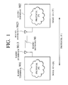
- Fig. 1 is a schematic diagram showing an exemplary radio network according to the first embodiment of the present invention.
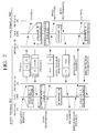
- Fig. 2 is a sequence chart for a processing of a packet transfer between radio terminals in the radio network of Fig. 1.
- Fig. 3 is a diagram showing exemplary correspondence tables to be used in the packet transfer between radio terminals in the radio network of Fig. 1.
- Fig. 4 is a diagram showing exemplary packet formats for a signaling request packet and a signaling response packet to be transferred between radio terminals in the radio network of Fig. 1.
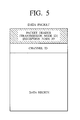
- Fig. 5 is a diagram showing an exemplary packet format of a data packet to be transferred between radio terminals in the radio network of Fig. 1.
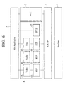
- Fig. 6 is a diagram showing an exemplary protocol stack to be executed by a radio terminal according to the first embodiment of the present invention.
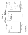
- Fig. 7 is a schematic diagram showing an exemplary radio network for executing the AV/C protocol between radio terminals according to the first embodiment of the present invention.
- Fig. 8 is a sequence chart for one exemplary processing of AV/C protocol execution in the radio network of Fig. 7.
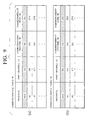
- Fig. 9 is a diagram showing exemplary correspondence tables to be used in the AV/C protocol execution in the radio network of Fig. 7.
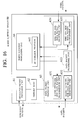
- Fig. 10 is a sequence chart for another exemplary processing of AV/C protocol execution in the radio network of Fig. 7.
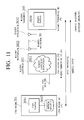
- Fig. 11 is a schematic diagram showing an exemplary radio network for executing the AV/C protocol between a radio terminal and an IEEE 1394 node via a radio gateway according to the second embodiment of the present invention.
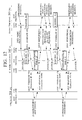
- Fig. 12 is a sequence chart for one exemplary processing of AV/C protocol execution in the radio network of Fig. 11.
- Fig. 13 is a diagram showing exemplary correspondence tables to be used in the AV/C protocol execution in the radio network of Fig. 11.
- Fig. 14 is a sequence chart for another exemplary processing of AV/C protocol execution in the radio network of Fig. 11.
- Fig. 15 is a block diagram showing an exemplary configuration of a radio terminal device according to the present invention.
- Fig. 16 is a block diagram showing an exemplary configuration of a radio gateway device according to the present invention.
- the protocol identifier of the AV control protocol is defined as a protocol identifier of a datalink layer packet in a radio system for executing data transfer after establishing a logical connection between radio terminals prior to data transfer between radio terminals.
- the AV/C protocol is added as a protocol identifier of an L2CAP packet in the Bluetooth.
- the AV control protocol can be identified from the protocol identifier at the datalink layer (a message type in this AV control protocol can be identified from at an upper layer protocol).
- the protocol identifier of the AV control protocol is defined as a protocol identifier of a datalink layer packet, for each message type separately.
- the AV/C command of the AV/C and the AV/C response of the AV/C protocol are added as protocol identifiers of an L2CAP packet in the Bluetooth.
- the AV control protocol as well as the message type in this AV control protocol can be identified from the protocol identifier at the datalink layer.
- datalink layer signaling packet are exchanged between radio terminals, where the datalink layer signaling packet contains a channel identifier indicating a logical channel that is set up for the purpose of transferring a packet on which information regarding this AV control protocol is loaded and a protocol identifier indicating this AV control protocol, and each radio terminal stores a correspondence information among the protocol identifier, a channel identifier of a channel that is set up for the own terminal, and the a channel identifier of a channel that is set up for a correspondent radio terminal, which are obtained through the signaling packet exchange.
- the data packet on which information regarding this AV control protocol is loaded will be transferred by attaching the correspondent channel identifier, such that the receiving side can judge that thr received packet is a packet regarding the AV control protocol, from the channel identifier attached to the received packet, at the datalink layer.
- the protocol identifier of the AV control protocol is defined as a protocol identifier of a datalink layer packet with respect to a radio network side, similarly as described above, at a radio gateway device for connecting the IEEE 1394 bus with a radio network for carrying out data transfer after establishing a logical connection between radio terminals prior to data transfer between radio terminals (such that the AV control protocol can be identified from a protocol identifier at a datalink layer).
- an access (read/write) with respect to a specific register on the IEEE 1394 bus can be set in correspondence with a protocol identifier on the radio network (in the case of the AV/C protocol, a register offset value for an AV/C command and a register offset value for an AV/C response can be set in correspondence with the same protocol identifier).
- the protocol identifier of the AV control protocol is defined as a protocol identifier of a datalink layer packet, for each message type separately, with respect to a radio network side (such that the AV control protocol as well the message type in this AV control protocol can be identified from the protocol identifier at the datalink layer).
- an access (read/write) with respect to a specific register on the IEEE 1394 bus can be set in correspondence with a protocol identifier on the radio network (in the case of the AV/C protocol, a register offset value for an AV/C command can be set in correspondence to a protocol identifier of the AV/C command, and a register offset value for an AV/C response can be set in correspondence with a protocol identifier of the AV/C response).
- a radio network section between the radio gateway device and the radio terminal is the same as between radio terminals described above. Also, in the packet relay processing between the radio network and the IEEE 1394 bus at the radio gateway device, a correspondence information is set up in advance by carrying out the signaling with the radio terminal as described above, and at a time of transferring a packet from the radio network side to the IEEE 1394 bus side, the fact that it is an AV/C command or an AV/C response of the AV/C protocol is ascertained from the channel identifier (or the channel identifier and the upper layer processing) in the received packet, and a packet is transferred to the IEEE 1394 side by describing a corresponding register offset value therein.
- the fact that it is an AV/C command or an AV/C response of the AV/C protocol is ascertained from the register offset value, and a packet is transferred to the radio network side by describing a correspondent channel identifier therein.
- the present invention even in the case of using a radio LAN system for carrying out data transfer after establishing a logical connection between radio terminals prior to data transfer between radio terminals, it is possible to execute a protocol such as AV/C protocol for which the protocol processing is to be carried out by using a combination of a command and a response as one set. Also, by assigning a channel identifier corresponding to a protocol to be executed in advance, it is possible to simplify the datalink layer processing on the radio terminal.
- the present invention it is possible to execute the AV/C protocol on the datalink protocol which starts communications after setting up a logical channel on a radio network. It is also possible to execute the AV/C protocol across such a radio network and the IEEE 1394 bus. In particular, it is possible to realize the AV data transfer control processing across the IEEE 1394 and the Bluetooth which is a kind of radio system using 2.4 GHz band.
- the first embodiment is directed to the case where a radio LAN system is assumed to be a system for carrying out data transfer after establishing a logical connection between radio terminals prior to data transfer between radio terminals.
- a radio LAN system is assumed to be a system for carrying out data transfer after establishing a logical connection between radio terminals prior to data transfer between radio terminals.
- the Bluetooth can be used as such a radio LAN system.
- Fig. 1 shows an exemplary basic configuration of a radio network in the first embodiment
- Fig. 2 shows an exemplary basic processing sequence in the case of carrying out packet transfer between radio terminals in the first embodiment.
- the radio LAN system shown in Fig. 1 at a time of transferring data related to some protocol P between two radio terminals 901 and 902 that are connected to a radio network 90 through radio interfaces 9013 and 9023, the processing shown in Fig. 2 will be carried out.
- the signaling processing is carried out between the radio terminals 901 and 902, such that a channel identifier (abbreviated hereafter as channel ID) regarding a logical connection is acquired at a datalink layer in each one of the radio terminals 901 and 902 (here it is assumed that channel IDs A and B are respectively acquired in this example). Note that the acquired channel ID information is exchanged between the radio terminals by the signaling processing.
- channel ID a channel identifier
- this logical connection is disconnected, and the channel IDs (A, B) that have been acquired at the datalink layer in the radio terminals 901 and 902 will be released.
- the prescribed condition can be satisfied when it is requested from the radio terminal 901 as indicated in Fig. 2, or when a prescribed period of time has elapsed since that channel ID is acquired, or when a prescribed period of time has elapsed since the data communication related to that channel ID was carried out last, for example.
- the channel can also be disconnected when the power of the radio terminal is turned off, or when the battery remaining power becomes less than a prescribed threshold, for example (in other words, the channel may not be disconnected until the power is turned off, for example).
- a part (a) of Fig. 3 shows an example of a correspondence table #1 to be created at the radio terminal 901. and a part (b) of Fig. 3 shows an example of a correspondence table #2 to be created at the radio terminal 902, in the signaling processing of the processing sequence of Fig. 2.
- Each correspondence table has a format in which a protocol, a channel ID of the own terminal (own channel ID) for executing that protocol, a node ID of a correspondent terminal (correspondent node ID), and a channel ID of that correspondent terminal (correspondent channel ID) are stored in correspondence.
- a part (a) of Fig. 4 shows an exemplary packet format for a signaling request packet and a part (b) of Fig. 4 shows an exemplary packet format for a signaling response packet, which are to be used in the signaling processing in this radio LAN system.
- the signaling information to be transferred contains the own channel ID (in the case of the signaling request packet) or the own channel ID and the correspondent channel ID (in the case of the signaling response packet) as well as the protocol ID of a protocol to be executed from now on.
- each one of the radio terminals 901 and 902 can maintain a correspondence between a newly acquired channel ID at the datalink layer and the upper layer protocol to be executed on the own terminal (by using that channel ID).
- the radio terminal on the transmitting side will transfer the packet by referring to the correspondence table in the own terminal and attaching a value of the channel ID on the correspondent terminal to which that upper layer protocol packet is to be transmitted (that is, the correspondent channel ID of the correspondence table shown in Fig. 3) to a header portion. Then, the radio terminal on the receiving side can ascertain even the upper layer protocol by referring to the correspondence table in the own terminal by using the channel ID attached to the packet as the own channel ID.
- Fig. 6 shows an exemplary protocol stack for the AV data transfer scheme to be executed by the radio terminals in the following description.
- the protocol stack of Fig. 6 is for the case of using the Bluetooth (in which a physical layer is Baseband and a datalink layer is L2CAP), that is currently under the process of standardization, as the radio system.
- the Bluetooth in which a physical layer is Baseband and a datalink layer is L2CAP
- the protocol stack of Fig. 6 is also for the case of executing the AV/C protocol as defined by the IEEE 1394 as the AV control protocol for transferring AV data and thereby providing a function such as the so called session control processing, at a time of executing an AV application at the radio terminal.
- the AV/C protocol recognizes nodes in terms of Units, and constituent elements (such as Display or VTR, for example) within each node in terms of SubUnits. Also, in the protocol for transferring the AV/C control commands (commands such as "play”, “stop”, “fast forward”, etc.), a transmission of a command and a reception of a response are to be carried out as one set.
- a group of protocols related to the actual AV data transfer are used (a block 4 of Fig. 6).
- various data such as video data, audio data and information data can be transferred by respective RTP (Realtime Transport Protocol) packets
- the RTP packets can be further encapsulated into L2CAP packets according to the datalink layer protocol of the Bluetooth
- the AV data transfer control information can be exchanged using the RTCP protocol (RTP Control Protocol), but the present invention is not necessarily limited to this case.
- Fig. 6 shows an internal configuration regarding the protocol processing of the radio terminal, which includes processing units for executing respective protocols, i.e., a Baseband processing unit 1 for executing the physical layer processing of the Bluetooth, an L2CAP processing unit 2 for executing the datalink layer processing of the Bluetooth, an AV/C protocol processing unit 3 for executing the AV/C protocol at an upper layer of the L2CAP processing unit 2, an AV data transfer processing unit 4 for executing a group of protocols related to the actual AV data transfer (the AV data transfer processing unit 4 has RTP processing units 41 for executing the RTP protocol, and a Video processing unit 43, an Audio processing unit 44, and Data processing unit 45 provided at an upper layer of the RTP processing unit 41, and an RTCP processing unit 42 for executing the RTCP protocol, for example), and an AV application processing unit 5 for executing an AV application at an upper layer of the AV/C protocol processing unit 3 and the AV data transfer processing unit 4.
- a Baseband processing unit 1 for executing the physical layer processing of
- a radio gateway device to be described in the second embodiment below will have a physical processing unit and a datalink layer processing unit of the IEEE 1394 bus, and a gateway function processing unit for enabling execution of the AV/C protocol across the radio network and the IEEE 1394, in addition to the configuration shown in Fig. 6.
- the gateway function processing unit executes a Proxy processing of the AV/C protocol, etc.
- the present invention is also applicable to the case where the AV data are to be transferred by being multiplexed using H.223 protocol or the like.
- an identifier for the AV/C protocol is defined as one of protocol identifiers (PSM (Protocol Service Multiplexor)) on the radio LAN, and the datalink layer protocol on the radio LAN carries out the packet transfer after setting up a logical connection at the datalink layer whenever a packet according to the AV/C protocol is to be transmitted. Also, whether it is an AV/C command or an AV/C response is identified at an upper layer (the AV/C protocol processing unit 3 of Fig. 6, for example) of the datalink layer rather than at the datalink layer.
- PSM Protocol Service Multiplexor
- Fig. 7 shows an exemplary configuration of a radio network in this case.
- a radio terminal 101 and a radio terminal 102 are connected to a radio network 10 through radio interfaces 1013 and 1023, and Fig. 7 depicts the case where MPEG4 data in the radio terminal 102 are to be playbacked/viewed at the radio terminal 101 through this radio network 10.
- Fig. 7 is also directed to the case of executing the AV/C protocol as defined by the IEEE 1394 as the AV control protocol for transmitting commands for the MPEG4 data transfer between the radio terminal 101 and the radio terminal 102.
- AV/C functions within each terminal are to be recognized in terms of SubUnits, and a command is to be transmitted with respect to this SubUnit.
- a Display SubUnit 1011 as a function for playbacking/viewing the NPEG4 data is provided at the radio terminal 101
- a VTR SubUnit 1021 as a function for transmitting the MPEG4 data and a MEPG4 source 1022 as a function for storing the MPEG4 data are provided at the radio terminal 102 (here it is assumed that the MPEG4 source 1022 is regarded as being contained in the VTR SubUnit 1021 on the AV/C protocol).
- Fig. 8 shows an exemplary procedure for executing the AV/C protocol between the radio terminal 101 and the radio terminal 102 in this case.
- a transfer of a command information and a transfer of a response information corresponding to that command are to be executed as one set. Consequently, in this embodiment, one logical channel (a channel ID at the datalink layer of each radio terminal) is assigned to each combination of a command and a response (one command processing set) in the case of executing the AV/C protocol between the radio terminal 101 and the radio terminal 102.
- Fig. 7 shows an exemplary case where there are only two radio terminals in the radio network 10, but in practice other radio terminals may also exist and the AV/C protocol may be executed between these other radio terminals. Consequently, in Fig. 8, the corresponding logical connection is disconnected immediately when the execution of the one command processing set is finished, such that the AV/C command and response to be received at respective radio terminals can easily identify the corresponding processing. Note that, as described above, there are various methods for controlling the disconnection of the logical connection, and it is even possible to use a method for not disconnecting the channel until the power is turned off.
- a part (a) of Fig. 9 shows an example of the correspondence table #1 to be maintained at the radio terminal 101 and a part (b) of Fig. 9 shows an example of the correspondence table #2 to be maintained at the radio terminal 102 in the series of processing described above.
- Each correspondence table shown in Fig. 9 registers the AV/C protocol as the protocol executed at each radio terminal, and in correspondence to that, a channel ID at the datalink layer of the own terminal ([A] in the correspondence table #1, [B] in the correspondence table #2), a node ID of the correspondent radio terminal which is executing this protocol, and a channel ID at the datalink layer of that correspondent radio terminal ([B] in the correspondence table #1, [A] in the correspondence table #2) are stored.
- a correspondence table it is possible to identify a value of the destination channel ID of a transmission packet in the AV/C response transmission processing or a protocol of a transfer target of a received packet in the reception processing. (2: Data transfer processing)
- An AV/C command is transmitted from the radio terminal 101.
- the portion related to the AV/C protocol on the correspondence table in each of the radio terminals 101 and 102 is deleted when the processing for transferring the AV/C command and the AV/C response is finished and the channel on the datalink layer of each radio terminal is disconnected (of course, various methods are possible here as described above).
- Fig. 10 shows an exemplary AV/C command transfer processing sequence in this case.
- the channel (which is assumed to be "A") for the AV/C protocol is assigned in advance at the radio terminal 101 and the radio terminal 102, and data for which a transmission request is made from the AV/C protocol processing unit (the AV/C protocol processing unit 3 of Fig. 6, for example) on each radio terminal will be always transmitted with a description of [A] as a value of its transfer target channel ID. Also, when a packet of the channel [A] is received at each radio terminal, data in this received packet will be always transferred to the AV/C protocol processing unit at the upper layer.
- the AV/C protocol processing unit on each radio terminal should carry out a processing for identifying an AV/C command transmitted by the own terminal which corresponds to the received AV/C response.
- the first embodiment even in the case of using a radio LAN system for carrying out data transfer after establishing a logical connection between radio terminals prior to data transfer between radio terminals, it is possible to execute a protocol such as AV/C protocol for which the protocol processing is to be carried out by using a combination of a command and a response as one set. Also, by assigning a channel ID corresponding to a protocol to be executed in advance, it is possible to simplify the datalink layer processing on the radio terminal.
- AV/C protocol for which the protocol processing is to be carried out by using a combination of a command and a response as one set.
- the second embodiment is directed to the case where the AV control protocol is to be executed between a radio terminal on the radio LAN system as described above and a 1394 node on the IEEE 1394 bus, in a system merging the IEEE 1394 bus with the radio LAN system for carrying out data transfer after establishing a logical connection between radio terminals prior to data transfer between radio terminals.
- an identifier for the AV/C protocol is defined as one of protocol identifiers (PSM (Protocol Service Multiplexor)) on the radio LAN, and the datalink layer protocol on the radio LAN carries out the packet transfer after setting up a logical connection at the datalink layer whenever a packet according to the AV/C protocol is to be transmitted. Also, whether it is an AV/C command or an AV/C response is identified at an upper layer (the AV/C protocol processing unit 3 of Fig. 6, for example) of the datalink layer rather than at the datalink layer.
- PSM Protocol Service Multiplexor
- Fig. 11 shows an exemplary configuration of a radio network in this case.
- a radio network 30 similar to that of Fig. 7 and an IEEE 1394 bus 20 are connected by a radio gateway 202, and a 1394 node 201 and a radio terminal 203 are provided on the IEEE 1394 bus 20 and the radio network 30 respectively (the radio terminal 203 and the radio gateway 202 are connected to the radio network 30 through radio interfaces 2022 and 2032, while the radio gateway 202 and the 1394 node 201 are connected to the IEEE 1394 bus 20).
- Fig. 11 depicts the case where MPEG2 data in the 1394 node 201 are to be playbacked/viewed at the radio terminal 203 through the IEEE 1394 bus 20, the radio gateway 202 and the radio network 30.
- Fig. 11 is also directed to the case of executing the AV/C protocol as defined by the IEEE 1394 as the AV control protocol for transmitting commands for the MPEG2 data transfer between the radio terminal 203 and the 1394 node 201.
- a Display SubUnit 2031 as a function for playbacking/viewing the MPEG2 data is provided at the radio terminal 203, while a VTR SubUnit 2011 as a function for transmitting the MPEG2 data and an MPEG2 source 2012 as a function for storing the MPEG2 data are provided at the 1394 node 201 (here it is assumed that the MPEG2 source 2012 is regarded as being contained in the VTR SubUnit 2011 on the AV/C protocol).
- the radio gateway 202 that connects the radio network 30 and the IEEE 1394 bus 20 is providing the Proxy function for connecting the radio network 30 and the IEEE 1394 bus 20 at a layer of the AV/C protocol. More specifically, (the radio gateway function 2021 of) the radio gateway 202 makes the VTR SubUnit 2011 that actually exists in the 1394 node 201 to appear as if it is existing in the radio gateway 202 with respect to the radio terminal 203. In other words, the radio terminal 203 recognizes the VTR SubUnit 2011 as existing in the radio gateway 202.
- the radio terminal 203 By carrying out such a Proxy processing, it becomes possible for the radio terminal 203 to execute the AV/C protocol with the 1394 bode 201 on the IEEE 1394 bus 20 by simply executing the AV/C protocol as defined on the radio network 30, without becoming conscious of the network configuration (the fact that the radio network 30 is actually operating by being connected to the IEEE 1394 bus 20).
- the radio gateway 202 can recognize this packet as a packet according to the AV/C protocol at the datalink layer, from the protocol identifier on the radio LAN contained in the header. Then, whether this packet is the AV/C command or the AV/C response can be ascertained at the upper layer.
- a register offset value corresponding to the AV/C command or AV/C response is described in the header of the packet.
- the radio gateway 202 can recognize this packet as a packet of the AV/C command or the AV/C response according to the AV/C protocol by reading a corresponding portion of the register according to the register offset value in the header.
- the protocol identifier on the radio LAN that corresponds to the AV/C protocol is described in the header of the packet.
- Fig. 12 shows an exemplary processing sequence in the case where this radio terminal 203 operates as a control node in the AV/C protocol to transmit a command to the 1394 node 201 and request transmission of the MPEG2 data on the 1394 node 201.
- a part of the signaling processing between the radio terminal 203 and the radio gateway 202 is omitted but this signaling processing is similar to the signaling processing between the radio terminal 101 and the radio terminal 102 in Fig. 8.
- the fact that the AV/C command and the AV/C response are to be executed as one set is also similar to Fig. 8.
- the disconnection of the logical connection is also similar to Fig. 8.
- the radio terminal 203 in order to request the MPEG2 data transfer, the radio terminal 203 first transmits a command (SubUnit_info) for collecting the SubUnit information on the 1394 node 201, and then according to a result of that, the radio terminal 203 transmits a command (Play) for requesting the data transmission with respect to the VTR SubUnit 2011 on the 1394 node 201.
- Fig. 12 shows an exemplary case where, at times of transmitting these two AV/C commands (SubUnit_info, Play), the data transfer is carried out after acquiring a logical channel on the datalink layer at each radio terminal (a channel is disconnected when the AV/C command transmission and the AV/C response reception are completed).
- the operation of the radio terminal 203 and a format of the correspondence table to be created by the radio terminal 203 are basically similar to those of the radio terminal 101 of the first embodiment, and the operation of the radio gateway 202 regarding the radio network section is basically similar to that of the radio terminal 102 of the first embodiment.
- the logical channel acquired for the purpose of the AV/C command transmission is to be disconnected every time the AV/C command transmission and the AV/C response reception are completed (of course, various methods are possible here as described above).
- Fig. 13 shows an example of the correspondence tables to be maintained at the radio gateway 202 in the series of processing described above, where a part (a) of Fig. 13 shows an example of the correspondence table "a" to be used in the processing related to the SubUnit_info command and its response in Fig. 12, and a part (b) of Fig. 13 shows an example of the correspondence table "b" to be used in the processing related to the Play command and its response in Fig. 12.
- Fig. 13 shows the case where each correspondence table maintains parameters as described above, but parameters to be maintained in the correspondence table may also include a value of SubUnit_ID which is a transfer target of the AV/C command or a type of the AV/C command.
- SubUnit_ID which is a transfer target of the AV/C command
- this information may be maintained without deleting it even when a corresponding AV/C response is received, because it can be expected that a response corresponding to a subsequent state change of the 1394 node will be returned.
- Fig. 14 shows an exemplary AV/C command transfer processing sequence in this case.
- a logical channel [B1] on the radio terminal 203 and a logical channel [A1] on the radio gateway 202 are assigned in advance, as logical channels for executing the AV/C protocol, between the radio terminal 203 and the radio gateway 202, and the AV/C command for which a request for transmission to the radio gateway 202 is made from the AV/C protocol processing unit (the AV/C protocol processing unit 3 of Fig. 6, for example) on the radio terminal 203 will be always transmitted with a description of [A1] as a value of its transfer target logical channel ID. Also, the AV/C response will be always transmitted with a description of [B1] as a value of its transfer target logical channel ID.
- Fig. 11 the exemplary network configuration of Fig. 11 is directed to the exemplary case where the radio terminal is a data receiving side and the 1394 node is a data transmitting side, but the case where the radio terminal is a transmitting side and the 1394 node is a receiving side is also possible similarly.
- the exemplary network configuration of Fig. 11 is directed to the exemplary case where there is only one radio gateway, but the case of carrying out data transfer between a first 1394 node connected to a first radio gateway via a first IEEE 1394 bus and a second 1394 node connected to a second radio gateway via a second IEEE 1394 bus is also possible similarly. Also, the case of carrying out data transfer between a first radio terminal connected to a first radio gateway via radio and a second radio terminal connected to a second radio gateway via radio where the first radio gateway and the second radio gateway are connected via an IEEE 1394 bus is also possible similarly.
- the AV/C protocol on the IEEE 1394 bus requires a description of a register offset value in the packet header in order to identify the AV/C protocol (in practice, different offset values are used for the AV/C command and the AV/C response).
- a protocol identifier on the radio LAN which indicates the AV/C protocol is defined and this protocol identifier indicating the AV/C protocol is to be described in the packet header at a time of transmitting a packet according to the AV/C protocol, and a command and a response are distinguished at the upper layer.
- protocol identifier indicating the AV/C command and a protocol identifier indicating the AV/C response as protocol identifiers on the radio LAN.
- different logical connections i.e., different channel identifiers, will be used for the AV/C command and the AV/C response.
- protocol identifiers for the AV/C command in a direction from the first radio terminal to the second radio terminal, the AV/C response in a direction from the first radio terminal to the second radio terminal, the AV/C command in a direction from the second radio terminal to the first radio terminal, and the AV/C response in a direction from the second radio terminal to the first radio terminal, as protocol identifiers on the radio LAN.
- different logical connections i.e., different channel identifiers, will be used for these four types of the protocol identifiers.
- the first and second embodiments even in the case of using a radio LAN system for carrying out data transfer after establishing a logical connection between radio terminals prior to data transfer between radio terminals, it is possible to execute a protocol such as AV/C protocol for which the protocol processing is to be carried out by using a combination of a command and a response as one set. Also, by assigning a channel ID corresponding to a protocol to be executed in advance, it is possible to simplify the datalink layer processing on the radio terminal.
- the first and second embodiments it becomes possible to realize the AV data transfer control processing across the radio network as described above and control a protocol that presupposes the IEEE 1394 such as AV/C protocol across the radio network and the IEEE 1394 bus.
- the channel identifier for the AV/C protocol (or for each one of the AV/C command and the AV/C response) is acquired (set up) at a time of signaling in the radio system, but it is also possible to acquire one or a plurality of channel identifiers in advance for the AV/C protocol (or for each one of the AV/C command and the AV/C response) (in the case where a plurality of channel identifiers are acquired, the radio terminal can suitably select and use a channel identifier that is available at that moment).
- the channel identifier for the AV/C protocol (or for each one of the AV/C command and the AV/C response) is appropriately assigned at each radio terminal, but it is also possible to define a plurality of channel identifiers available for the AV/C protocol (or for each one of the AV/C command and the AV/C response) with respect to all terminals (in which case the radio terminal can suitably select and use a channel identifier from these plurality of channel identifiers).
- a unique channel identifier for the AV/C protocol with respect to all terminals in advance. It is also possible to define a unique channel identifier for the AV/C command with respect to all terminals in advance, while defining a unique channel identifier for the AV/C response with respect to all terminals in advance.
- the above described embodiments are directed to the exemplary case where the radio terminal of an AV data receiving side transmits a signaling request (at a time of issuing a playback request of the AV/C protocol, for example) and in response to this the radio terminal of an AV data transmitting side transmits a signaling response, but the case where the radio terminal of an AV data transmitting side transmits a signaling request (at a time of issuing a reception request of the AV/C protocol, for example) and in response to this the radio terminal of an AV data receiving side transmits a signaling response is also possible similarly.
- the above described embodiments are directed to the exemplary case of using the Bluetooth, but the present invention is also applicable to radio terminals of any other radio LAN system for carrying out data transfer after establishing a logical connection between radio terminals prior to data transfer between radio terminals.
- the above described embodiments are directed to the exemplary case of using the AV/C protocol as the AV control protocol for the AV data transfer, but the present invention is also applicable to the case of using any other AV control protocol.
- the present invention is equally applicable to a home network and a network provided in an office or any other environment.
- each radio terminal in the above described embodiments can be realized by a radio terminal device 50 as shown in Fig. 15, for use in a radio system for carrying out data transfer after establishing a logical connection between radio terminals or gateways prior to data transfer between radio terminals or gateways.
- This radio terminal device 50 of Fig. 15 comprises: a signaling packet exchange unit 51 for exchanging signaling packets at a datalink layer with a correspondent radio terminal or gateway prior to an exchange of data packets on which the information regarding the AV control protocol is loaded, where each signaling packet contains a channel identifier indicating a logical channel that is set up for transferring the data packets and a protocol identifier indicating the AV control protocol; a memory unit 52 for storing a correspondence information among the protocol identifier, the channel identifier that is set up for the radio terminal device, and the channel identifier that is set up for the correspondent radio terminal or gateway, which are obtained through an exchange of the signaling packets; a data packet exchange unit 53 for exchanging the data packets with the correspondent radio terminal or gateway, according to the correspondence information; and a radio terminal processing unit 54 for carrying out the processing of the radio terminal.
- a signaling packet exchange unit 51 for exchanging signaling packets at a datalink layer with a correspondent radio terminal or gateway prior to an exchange of
- the data packet exchange unit 53 includes a data packet transmission unit 531 for transmitting an outgoing data packet by attaching the channel identifier that is set up for the correspondent radio terminal or gateway and that is obtained by referring to the correspondence information; a data packet reception unit 532 for receiving an incoming data packet from the correspondent radio terminal or gateway; and a data packet processing unit 533 for giving the information regarding the AV control protocol as contained in the incoming data packet to the AV control protocol, when the incoming data packet is judged as a packet regarding the AV control protocol by referring to the correspondence information according to the channel identifier as described in the incoming data packet,
- the AV control protocol 541 is provided in the radio terminal processing unit 54.
- each radio gateway in the above described embodiments can be realized by a radio gateway device 60 as shown in Fig. 16, for connecting an IEEE 1394 bus with a radio network for carrying out data transfer after establishing a logical connection between radio terminals or gateways prior to data transfer between radio terminals or gateways.
- This radio gateway device 60 of Fig. 16 comprises: a signaling packet exchange unit 61 for exchanging signaling packets at a datalink layer with a correspondent radio terminal or gateway on the radio network prior to an exchange of data packets on which information regarding an AV control protocol is loaded, where each signaling packet contains a channel identifier indicating a logical channel that is set up for transferring the data packets and a protocol identifier indicating the AV control protocol; a memory unit 62 for storing a correspondence information among the protocol identifier, the channel identifier that is set up for the radio gateway device, and the channel identifier that is set up for the correspondent radio terminal or gateway, which are obtained through an exchange of the signaling packets; a data packet transfer unit 63 for transferring the data packets from a radio network side to an IEEE 1394 bus side or from the IEEE 1394 bus side to the radio network side, according to the correspondence information; and a radio gateway processing unit 64 for carrying out the processing of the radio gateway.
- the data packet transfer unit 63 includes a radio network side data packet transmission unit 631 for transmitting an outgoing data packet on which the command of the AV control protocol or the response of the AV control protocol is loaded, to the IEEE 1394 side, by describing a register offset value indicating the command of the AV control protocol or a register offset value indicating the response of the AV control protocol in the outgoing data packet; a radio network side data packet reception unit 632 for receiving an incoming data packet to be transferred to the IEEE 1394 side from the radio network side; a data packet processing unit 633 for checking whether a message type of the incoming data packet is a command of the AV control protocol or a response of the AV control protocol when the channel identifier that is set up for the radio gateway device is described in the incoming data packet; an IEEE 1394 side data packet reception unit 634 for receiving an incoming data packet to be transferred to the radio network side from the IEEE 1394 side; and an IEEE 1394 side data packet transmission unit 635 for transmitting an outgoing data packet on which a command of
- the AV control protocol 641 is provided in the radio gateway processing unit 64.
- radio terminal and the radio gateway of each of the above described embodiments can be conveniently implemented in a form of a software package.
- Such a software package can be a computer program product which employs a storage medium including stored computer code which is used to program a computer to perform the disclosed function and process of the present invention.
- the storage medium may include, but is not limited to, any type of conventional floppy disks, optical disks, CD-ROMs, magneto-optical disks, ROMs, RAMs, EPROMs, EEPROMs, magnetic or optical cards, or any other suitable media for storing electronic instructions.
Landscapes
- Engineering & Computer Science (AREA)
- Computer Networks & Wireless Communication (AREA)
- Signal Processing (AREA)
- Multimedia (AREA)
- Mobile Radio Communication Systems (AREA)
- Small-Scale Networks (AREA)
- Communication Control (AREA)
Abstract
Description
(1: Signaling processing) A logical connection is established between the
- At the
radio terminal 101, the AV/C protocol with respect to theradio terminal 102 is activated, and a request for acquiring a logical connection for this AV/C command transfer (signaling request) is transferred to the datalink layer processing unit (theL2CAP processing unit 2 of Fig. 6, for example) within the own terminal. - After a channel (which is assumed to be "A") is
acquired within the
radio terminal 101, a request for acquiring a channel of theradio terminal 102 corresponding to the channel "A" is transferred to theradio terminal 102. A packet to be transferred here contains a description of a channel ID at the radio terminal 101 [A] and a protocol ID of the protocol to be executed [AV/C] entered by the datalink layer processing unit (see a part (a) of Fig. 4). - At the
radio terminal 102 which received the above channel acquisition request, when the datalink processing unit recognizes that the above protocol ID described in the channel acquisition request indicates the AV/C protocol, a channel (which is assumed to be "B") is acquired as a channel for executing the AV/C protocol with theradio terminal 101. Also, this fact (the fact that the channel "A" is acquired at theradio terminal 101 side and the channel "B" is acquired at theradio terminal 102 side as the logical connection for the AV/C command transfer) is notified to the AV/C protocol processing unit (the AV/C protocol processing unit 3 of Fig. 6, for example) on the own terminal. - A channel acquisition response (signaling response)
indicating that the channel [B] is assigned in response to
a request from the channel [A] on the
radio terminal 101 is transmitted from theradio terminal 102 to theradio terminal 101. A packet to be transferred here contains a description of the channel ID at the radio terminal 101 [A], the corresponding channel ID at the radio terminal 102 [B], and the protocol ID of the protocol to be executed [AV/C] entered by the datalink layer processing unit (see a part (b) of Fig. 4). Also, this fact (the fact that the channel "A" is acquired at theradio terminal 101 side and the channel "B" is acquired at theradio terminal 102 side as the logical connection for the AV/C command transfer) is notified to the AV/C protocol processing unit. - Note that, when the channel [B] is acquired, the
correspondence table # 2 storing the correspondence of the channels is created at the radio terminal 102 (see a part (b) of Fig. 9). - At the
radio terminal 101 which received the above channel acquisition response, the fact that the channel ID [B] is acquired in theradio terminal 102 in correspondence to the channel ID [A] acquired in the own terminal in order to execute the AV/C protocol is recognized by referring to the above identification information described in the channel acquisition response. - Note that, at this point, the
correspondence table # 1 storing the correspondence of the channels is created at the radio terminal 101 (see a part (a) of Fig. 9).
(2: Data transfer processing) An AV/C command is transmitted from the
- A desired AV/C command is transmitted from the
radio terminal 101 toward theradio terminal 102. Namely, at the datalink layer processing unit which received the AV/C command from the AV/C protocol processing unit on the own terminal, this AV/C command is transmitted to theradio terminal 102 by attaching the correspondent channel ID (= "B") obtained by referring to the above described correspondence table #1 (AV/C command transmission processing). A packet to be transferred at this point contains a description of the channel ID on the radio terminal 102 [B] as an information on a destination of this packet, but a description of the own channel ID [A] and the protocol ID of the protocol [AV/C] are not contained (see Fig. 5). - At the
radio terminal 102 which received the above packet (on which the AV/C command is loaded), when it is recognized that data in this packet is related to the AV/C protocol by referring to the above describedcorrespondence table # 2 by using the channel ID (= "B") described in the packet as the own channel ID, this data (the AV/C command in this case) is given to the AV/C protocol processing unit on the own terminal and the processing corresponding to this data (AV/C command) is carried out at the AV/C protocol processing unit, and an AV/C response containing a result of the processing which is produced at the AV/C protocol processing unit is transmitted to theradio terminal 101 by attaching the correspondent channel ID (= "A") obtained by referring to the above described correspondence table #2 (AV/C response transmission processing). A packet to be transferred at this point contains a description of the channel ID on the radio terminal 101 [A] as an information on a destination of this packet (but a description of the own channel ID [B] and the protocol ID of the protocol [AV/C] are not contained). - Similarly, at the
radio terminal 101 which received the above packet (on which the AV/C command is loaded), when it is recognized that data in this packet is related to the AV/C protocol by referring to the above describedcorrespondence table # 1 by using the channel ID (= "A") described in the packet as the own channel ID, this data (the AV/C response in this case) is given to the AV/C protocol processing unit on the own terminal (and the necessary processing is carried out at the AV/C protocol processing unit).
- The
radio terminal 101 disconnects the channel "A" in the own terminal, and a request for disconnecting the channel "B" in theradio terminal 102 corresponding to the channel "A" is transmitted to theradio terminal 102. - The
radio terminal 102 disconnects the channel "B" in the own terminal, and transmits a disconnection processing confirmation message to the radio terminal 10-1.
- At the
radio gateway 202, a relationship between the logical channel [A1] on the radio network and the transaction ID (= M in Fig. 12) on theIEEE 1394 bus to which the AV/C command is to be transferred is stored into the correspondence table at a time of transferring the AV/C command to the 1394 node 201 (see a part (a) of Fig. 13). - The AV/C command is transferred from the
radio gateway 202 to the 1394node 201, and a processing corresponding to that is carried out at the 1394node 201. - After the 1394
node 201 carried out the processing corresponding to the transmitted AV/C command (collecting the SubUnit information within the own terminal and creating a packet), the processing result is transferred to theradio gateway 202 as the AV/C response. At this point, a value of the transaction ID of the AV/C response on theIEEE 1394 bus is M.
Claims (32)
- An information transfer method for transferring information regarding an AV control protocol in a radio system for carrying out data transfer after establishing a logical connection between radio terminals or gateways prior to data transfer between radio terminals or gateways, the method comprising the steps of:exchanging signaling packets for signaling at a datalink layer between the radio terminals or gateways prior to an exchange of data packets on which the information regarding the AV control protocol is loaded, each signaling packet containing a channel identifier indicating a logical channel that is set up for transferring the data packets and a protocol identifier indicating the AV control protocol, such that a signaling packet transmitted from each radio terminal or gateway indicates a channel identifier that is set up for the each radio terminal or gateway and a signaling packet received from a correspondent radio terminal or gateway indicates a channel identifier that is set up for the correspondent radio terminal or gateway;storing at the each radio terminal or gateway a correspondence information obtained through an exchange of the signaling packets, the correspondence information indicating a correspondence among the protocol identifier, the channel identifier that is set up for the each radio terminal or gateway, and the channel identifier that is set up for the correspondent radio terminal or gateway; andtransferring the data packets between the radio terminals or gateways, according to the correspondence information.
- The method of claim 1, wherein the transferring step transmits an outgoing data packet by attaching the channel identifier that is set up for the correspondent radio terminal or gateway and that is obtained by referring to the correspondence information.
- The method of claim 1, wherein the transferring step receives an incoming data packet from the correspondent radio terminal or gateway, and gives the information regarding the AV control protocol as contained in the incoming data packet to the AV control protocol, when the incoming data packet is judged as a packet regarding the AV control protocol by referring to the correspondence information according to the channel identifier as described in the incoming data packet,
- The method of claim 1, wherein the exchanging step uses the channel identifier indicating the logical channel that is set up at a time of the signaling.
- The method of claim 1, wherein the exchanging step uses the channel identifier indicating the logical channel that is set up prior to the signaling.
- The method of claim 1, wherein the exchanging step uses the channel identifier indicating the logical channel that is specified with respect to all radio terminals or gateways in advance.
- The method of claim 1, wherein values of the protocol identifier are defined separately for different message types in the AV control protocol, andthe exchanging step carries out the signaling for each message type of the AV control protocol, using different channel identifiers for different message types in the AV control protocol.
- An information transfer method for transferring information regarding an AV control protocol at a radio gateway connecting an IEEE 1394 bus with a radio network for carrying out data transfer after establishing a logical connection between radio terminals or gateways prior to data transfer between radio terminals or gateways, the method comprising the steps of:exchanging signaling packets for signaling at a datalink layer with a correspondent radio terminal or gateway on the radio network prior to an exchange of data packets on which the information regarding the AV control protocol is loaded, each signaling packet containing a channel identifier indicating a logical channel that is set up for transferring the data packets and a protocol identifier indicating the AV control protocol, such that a signaling packet transmitted from the radio gateway indicates a channel identifier that is set up for the radio gateway and a signaling packet received from the correspondent radio terminal or gateway indicates a channel identifier that is set up for the correspondent radio terminal or gateway;storing a correspondence information obtained through an exchange of the signaling packets, the correspondence information indicating a correspondence among the protocol identifier, the channel identifier that is set up for the radio gateway, and the channel identifier that is set up for the correspondent radio terminal or gateway; andtransferring the data packets from a radio network side to an IEEE 1394 bus side or from the IEEE 1394 bus side to the radio network side, according to the correspondence information.
- The method of claim 8, wherein the transferring step includes the steps of:receiving an incoming data packet to be transferred to the IEEE 1394 side from the radio network side;checking whether a message type of the incoming data packet is a command of the AV control protocol or a response of the AV control protocol when the channel identifier that is set up for the radio gateway is described in the incoming data packet; andtransmitting an outgoing data packet on which the command of the AV control protocol or the response of the AV control protocol is loaded, to the IEEE 1394 side, by describing a register offset value indicating the command of the AV control protocol or a register offset value indicating the response of the AV control protocol in the outgoing data packet.
- The method of claim 8, wherein the transferring step includes the steps of:receiving an incoming data packet to be transferred to the radio network side from the IEEE 1394 side; andtransmitting an outgoing data packet on which a command of the AV control protocol or a response of the AV control protocol is loaded, to the radio network side, by describing the channel identifier that is set up for the correspondent radio terminal or gateway in the outgoing data packet, when a register offset value indicating the command of the AV control protocol or a register offset value indicating the response of the AV control protocol is described in the incoming data packet.
- The method of claim 8, wherein the exchanging step uses the channel identifier indicating the logical channel that is set up at a time of the signaling.
- The method of claim 8, wherein the exchanging step uses the channel identifier indicating the logical channel that is set up prior to the signaling.
- The method of claim 8, wherein the exchanging step uses the channel identifier indicating the logical channel that is specified with respect to all radio terminals or gateways in advance.
- The method of claim 8, wherein values of the protocol identifier are defined separately for different message types in the AV control protocol, and
the exchanging step carries out the signaling for each message type of the AV control protocol, using different channel identifiers for different message types in the AV control protocol. - The method of claim 8, wherein the transferring step transmits data packets on which one set of the command of the AV control protocol and the response of the AV control protocol are loaded by attaching an identical transaction identifier to the data packets.
- A radio terminal device in a radio system for carrying out data transfer after establishing a logical connection between radio terminals or gateways prior to data transfer between radio terminals or gateways, the radio terminal device comprising:a signaling packet exchange unit configured to exchange signaling packets for signaling at a datalink layer with a correspondent radio terminal or gateway prior to an exchange of data packets on which the information regarding the AV control protocol is loaded, each signaling packet containing a channel identifier indicating a logical channel that is set up for transferring the data packets and a protocol identifier indicating the AV control protocol, such that a signaling packet transmitted from the radio terminal device indicates a channel identifier that is set up for the radio terminal device and a signaling packet received from the correspondent radio terminal or gateway indicates a channel identifier that is set up for the correspondent radio terminal or gateway;a memory unit configured to store a correspondence information obtained through an exchange of the signaling packets, the correspondence information indicating a correspondence among the protocol identifier, the channel identifier that is set up for the radio terminal device, and the channel identifier that is set up for the correspondent radio terminal or gateway; anda data packet exchange unit configured to exchange the data packets with the correspondent radio terminal or gateway, according to the correspondence information.
- The radio terminal device of claim 16, wherein the data packet exchange unit includes:
a data packet transmission unit configured to transmit an outgoing data packet by attaching the channel identifier that is set up for the correspondent radio terminal or gateway and that is obtained by referring to the correspondence information. - The radio terminal device of claim 16, wherein the data packet exchange unit includes:a data packet reception unit configured to receive an incoming data packet from the correspondent radio terminal or gateway; anda data packet processing unit configured to give the information regarding the AV control protocol as contained in the incoming data packet to the AV control protocol, when the incoming data packet is judged as a packet regarding the AV control protocol by referring to the correspondence information according to the channel identifier as described in the incoming data packet,
- The radio terminal device of claim 16, wherein the signaling packet exchange unit uses the channel identifier indicating the logical channel that is set up at a time of the signaling.
- The radio terminal device of claim 16, wherein the signaling packet exchange unit uses the channel identifier indicating the logical channel that is set up prior to the signaling.
- The radio terminal device of claim 16, wherein the signaling packet exchange unit uses the channel identifier indicating the logical channel that is specified with respect to all radio terminals or gateways in advance.
- The radio terminal device of claim 16, wherein values of the protocol identifier are defined separately for different message types in the AV control protocol, and
the signaling packet exchange unit carries out the signaling for each message type of the AV control protocol, using different channel identifiers for different message types in the AV control protocol. - A radio gateway device connecting an IEEE 1394 bus with a radio network for carrying out data transfer after establishing a logical connection between radio terminals or gateways prior to data transfer between radio terminals or gateways, the radio gateway device comprising:a signaling packet exchange unit configured to exchange signaling packets for signaling at a datalink layer with a correspondent radio terminal or gateway on the radio network prior to an exchange of data packets on which information regarding an AV control protocol is loaded, each signaling packet containing a channel identifier indicating a logical channel that is set up for transferring the data packets and a protocol identifier indicating the AV control protocol, such that a signaling packet transmitted from the radio gateway device indicates a channel identifier that is set up for the radio gateway device and a signaling packet received from the correspondent radio terminal or gateway indicates a channel identifier that is set up for the correspondent radio terminal or gateway;a memory unit configured to store a correspondence information obtained through an exchange of the signaling packets, the correspondence information indicating a correspondence among the protocol identifier, the channel identifier that is set up for the radio gateway device, and the channel identifier that is set up for the correspondent radio terminal or gateway; anda data packet transfer unit configured to transfer the data packets from a radio network side to an IEEE 1394 bus side or from the IEEE 1394 bus side to the radio network side, according to the correspondence information.
- The radio gateway device of claim 23, wherein the data packet transfer unit includes:a radio network side data packet reception unit configured to receive an incoming data packet to be transferred to the IEEE 1394 side from the radio network side;a data packet processing unit configured to check whether a message type of the incoming data packet is a command of the AV control protocol or a response of the AV control protocol when the channel identifier that is set up for the radio gateway device is described in the incoming data packet; anda radio network side data packet transmission unit configured to transmit an outgoing data packet on which the command of the AV control protocol or the response of the AV control protocol is loaded, to the IEEE 1394 side, by describing a register offset value indicating the command of the AV control protocol or a register offset value indicating the response of the AV control protocol in the outgoing data packet.
- The radio gateway device of claim 23, wherein the data packet transfer unit includes:an IEEE 1394 side data packet reception unit configured to receive an incoming data packet to be transferred to the radio network side from the IEEE 1394 side; andan IEEE 1394 side data packet transmission unit configured to transmit an outgoing data packet on which a command of the AV control protocol or a response of the AV control protocol is loaded, to the radio network side, by describing the channel identifier that is set up for the correspondent radio terminal or gateway in the outgoing data packet, when a register offset value indicating the command of the AV control protocol or a register offset value indicating the response of the AV control protocol is described in the incoming data packet.
- The radio gateway device of claim 23, wherein the signaling packet exchange unit uses the channel identifier indicating the logical channel that is set up at a time of the signaling.
- The radio gateway device of claim 23, wherein the signaling packet exchange unit uses the channel identifier indicating the logical channel that is set up prior to the signaling.
- The radio gateway device of claim 23, wherein the signaling packet exchange unit uses the channel identifier indicating the logical channel that is specified with respect to all radio terminals or gateways in advance.
- The radio gateway device of claim 23, wherein values of the protocol identifier are defined separately for different message types in the AV control protocol, and
the signaling packet exchange unit carries out the signaling for each message type of the AV control protocol, using different channel identifiers for different message types in the AV control protocol. - The radio gateway device of claim 23, wherein the data packet transfer unit transmits data packets on which one set of the command of the AV control protocol and the response of the AV control protocol are loaded by attaching an identical transaction identifier to the data packets.
- A computer usable medium having computer readable program codes embodied therein for causing a computer to function as a radio terminal device in a radio system for carrying out data transfer after establishing a logical connection between radio terminals or gateways prior to data transfer between radio terminals or gateways, the computer readable program codes include:a first computer readable program code for causing said computer to exchange signaling packets for signaling at a datalink layer with a correspondent radio terminal or gateway prior to an exchange of data packets on which the information regarding the AV control protocol is loaded, each signaling packet containing a channel identifier indicating a logical channel that is set up for transferring the data packets and a protocol identifier indicating the AV control protocol, such that a signaling packet transmitted from the radio terminal device indicates a channel identifier that is set up for the radio terminal device and a signaling packet received from the correspondent radio terminal or gateway indicates a channel identifier that is set up for the correspondent radio terminal or gateway;a second computer readable program code for causing said computer to store a correspondence information obtained through an exchange of the signaling packets, the correspondence information indicating a correspondence among the protocol identifier, the channel identifier that is set up for the radio terminal device, and the channel identifier that is set up for the correspondent radio terminal or gateway; anda third computer readable program code for causing said computer to exchange the data packets with the correspondent radio terminal or gateway, according to the correspondence information.
- A computer usable medium having computer readable program codes embodied therein for causing a computer to function as a radio gateway device connecting an IEEE 1394 bus with a radio network for carrying out data transfer after establishing a logical connection between radio terminals or gateways prior to data transfer between radio terminals or gateways, the computer readable program codes include:a first computer readable program code for causing said computer to exchange signaling packets at a datalink layer with a correspondent radio terminal or gateway on the radio network prior to an exchange of data packets on which information regarding an AV control protocol is loaded, each signaling packet containing a channel identifier indicating a logical channel that is set up for transferring the data packets and a protocol identifier indicating the AV control protocol, such that a signaling packet transmitted from the radio gateway device indicates a channel identifier that is set up for the radio gateway device and a signaling packet received from the correspondent radio terminal or gateway indicates a channel identifier that is set up for the correspondent radio terminal or gateway;a second computer readable program code for causing said computer to store a correspondence information obtained through an exchange of the signaling packets, the correspondence information indicating a correspondence among the protocol identifier, the channel identifier that is set up for the radio gateway device, and the channel identifier that is set up for the correspondent radio terminal or gateway; anda third computer readable program code for causing said computer to transfer the data packets from a radio network side to an IEEE 1394 bus side or from the IEEE 1394 bus side to the radio network side, according to the correspondence information.
Applications Claiming Priority (2)
| Application Number | Priority Date | Filing Date | Title |
|---|---|---|---|
| JP37176199 | 1999-12-27 | ||
| JP37176199A JP3715494B2 (en) | 1999-12-27 | 1999-12-27 | Information transfer method, wireless terminal and wireless gateway device |
Publications (3)
| Publication Number | Publication Date |
|---|---|
| EP1113623A2 true EP1113623A2 (en) | 2001-07-04 |
| EP1113623A3 EP1113623A3 (en) | 2002-12-11 |
| EP1113623B1 EP1113623B1 (en) | 2006-05-24 |
Family
ID=18499261
Family Applications (1)
| Application Number | Title | Priority Date | Filing Date |
|---|---|---|---|
| EP20000311696 Expired - Lifetime EP1113623B1 (en) | 1999-12-27 | 2000-12-27 | Data transfer method using layer 2 signaling of protocol identifier, radio terminal and radio gateway device |
Country Status (4)
| Country | Link |
|---|---|
| US (2) | US6829228B2 (en) |
| EP (1) | EP1113623B1 (en) |
| JP (1) | JP3715494B2 (en) |
| DE (1) | DE60028174T2 (en) |
Cited By (1)
| Publication number | Priority date | Publication date | Assignee | Title |
|---|---|---|---|---|
| US10693906B2 (en) | 2015-09-24 | 2020-06-23 | Saudi Arabian Oil Company | Providing secure data transfer between networks |
Families Citing this family (12)
| Publication number | Priority date | Publication date | Assignee | Title |
|---|---|---|---|---|
| WO2002056548A1 (en) * | 2001-01-16 | 2002-07-18 | Sony Corporation | Data transmission method, data transmitter, record medium, and program |
| JP3971984B2 (en) * | 2002-10-15 | 2007-09-05 | 松下電器産業株式会社 | Communication apparatus and communication method |
| FR2864870A1 (en) * | 2004-01-06 | 2005-07-08 | Thomson Licensing Sa | METHOD FOR TRANSMITTING IEEE 1394 DATA ON A WIRELESS CONNECTION AND APPARATUS IMPLEMENTING THE METHOD |
| EP1560385B1 (en) * | 2004-02-02 | 2010-04-14 | Sony Deutschland GmbH | Method for data transfer in a multi-standard network |
| US8249106B2 (en) * | 2004-08-23 | 2012-08-21 | Alcatel Lucent | Extended cellular telephony protocol |
| EP1932760A1 (en) * | 2006-12-13 | 2008-06-18 | Saab Ab | A radio communication system for providing both voice and data communication services over radio communication channels and a method for use in a radio communication system |
| KR100800589B1 (en) * | 2006-12-20 | 2008-02-04 | 엘지전자 주식회사 | Information processing device and its operation method |
| EP2434834B1 (en) * | 2007-07-30 | 2016-09-07 | Marvell World Trade Ltd. | Simultaneously maintaining bluetooth and 802.11 connections to increase data throughput |
| US8489084B2 (en) | 2008-03-31 | 2013-07-16 | At&T Mobility Ii Llc | Over the air programming via cellular broadcast |
| US9451331B2 (en) | 2011-01-15 | 2016-09-20 | Lattice Semiconductor Corporation | Proxy device operation in command and control network |
| WO2013112084A1 (en) * | 2012-01-26 | 2013-08-01 | Telefonaktiebolaget L M Ericsson (Publ) | A transmitting radio node, a receiving radio node, and methods therein for handling data packets within a radio bearer |
| CN105917670A (en) * | 2013-12-10 | 2016-08-31 | 索诺瓦公司 | Wireless stereo hearing assistance system |
Family Cites Families (7)
| Publication number | Priority date | Publication date | Assignee | Title |
|---|---|---|---|---|
| WO1994022253A1 (en) * | 1993-03-20 | 1994-09-29 | International Business Machines Corporation | Method and apparatus for extracting connection information from protocol headers |
| US6523696B1 (en) * | 1996-10-15 | 2003-02-25 | Kabushiki Kaisha Toshiba | Communication control device for realizing uniform service providing environment |
| JPH10174073A (en) | 1996-12-11 | 1998-06-26 | Sony Corp | Transmission device and transmission method |
| FI105140B (en) * | 1997-04-15 | 2000-06-15 | Nokia Networks Oy | Routing Decision Making on a Connection Packet Network |
| JP3922817B2 (en) | 1998-06-30 | 2007-05-30 | 株式会社東芝 | Communication node and communication terminal |
| JP3576019B2 (en) * | 1998-12-28 | 2004-10-13 | 株式会社東芝 | Communication node |
| JP3629174B2 (en) * | 1999-12-27 | 2005-03-16 | 株式会社東芝 | Data transfer method and wireless terminal |
-
1999
- 1999-12-27 JP JP37176199A patent/JP3715494B2/en not_active Expired - Fee Related
-
2000
- 2000-12-27 DE DE2000628174 patent/DE60028174T2/en not_active Expired - Lifetime
- 2000-12-27 EP EP20000311696 patent/EP1113623B1/en not_active Expired - Lifetime
- 2000-12-27 US US09/748,017 patent/US6829228B2/en not_active Expired - Fee Related
-
2004
- 2004-10-13 US US10/962,493 patent/US6993005B2/en not_active Expired - Fee Related
Cited By (1)
| Publication number | Priority date | Publication date | Assignee | Title |
|---|---|---|---|---|
| US10693906B2 (en) | 2015-09-24 | 2020-06-23 | Saudi Arabian Oil Company | Providing secure data transfer between networks |
Also Published As
| Publication number | Publication date |
|---|---|
| EP1113623A3 (en) | 2002-12-11 |
| DE60028174T2 (en) | 2006-10-05 |
| JP3715494B2 (en) | 2005-11-09 |
| JP2001186166A (en) | 2001-07-06 |
| EP1113623B1 (en) | 2006-05-24 |
| US6829228B2 (en) | 2004-12-07 |
| DE60028174D1 (en) | 2006-06-29 |
| US20010006518A1 (en) | 2001-07-05 |
| US6993005B2 (en) | 2006-01-31 |
| US20050047388A1 (en) | 2005-03-03 |
Similar Documents
| Publication | Publication Date | Title |
|---|---|---|
| EP1113644B1 (en) | Data transfer method and radio terminal for executing transport layer protocol on radio network | |
| US7606243B2 (en) | Radio communication system and radio terminal device using faster and slower radio networks cooperatively | |
| US6728244B1 (en) | Communication node for enabling interworking of network using request/response based data transfer and network using non-request/response based data transfer | |
| US7158483B1 (en) | Communication node and communication terminal | |
| KR100549480B1 (en) | Information communication system, information communication method, information signal processing device, information signal processing method and storage medium, serial bus bridge and terminal device | |
| US6446142B1 (en) | Method of and apparatus for dynamically binding subobjects into objects to represent functions and characteristics of a device within an IEEE 1394 serial bus network | |
| US6366964B1 (en) | Method of and apparatus for dynamically enumerating objects representing devices within an IEEE 1394 serial bus networking | |
| EP1113623B1 (en) | Data transfer method using layer 2 signaling of protocol identifier, radio terminal and radio gateway device | |
| US20030074450A1 (en) | Home network system and method of allocating node identification | |
| EP1266484B1 (en) | Method for isochronous resource management in a network based on hiperlan 2 technology | |
| JP2001521356A (en) | Method and apparatus for detecting and controlling the transmission direction of a bus packet in an IEEE 1394 serial bus node | |
| US6408355B1 (en) | Method for releasing isochronous transaction in bus network, bus network utilizing the method thereof and information provision medium | |
| KR100226781B1 (en) | Method for recognizing node | |
| JPH1155297A (en) | Transmission medium connection device and storage medium | |
| JP2004064665A (en) | Data transfer device, transmission device, reception device, and control method thereof | |
| EP0877321B1 (en) | State information managing method and system using the same | |
| US7002928B1 (en) | IEEE 1394-based protocol repeater | |
| EP1063817A2 (en) | Transmission method and electrical equipment | |
| JP2002217928A (en) | Communication control method and communication unit | |
| WO2000023869A1 (en) | Dynamic enumeration of device within a network | |
| KR20000009719A (en) | Node control method in bus system |
Legal Events
| Date | Code | Title | Description |
|---|---|---|---|
| PUAI | Public reference made under article 153(3) epc to a published international application that has entered the european phase |
Free format text: ORIGINAL CODE: 0009012 |
|
| 17P | Request for examination filed |
Effective date: 20010116 |
|
| AK | Designated contracting states |
Kind code of ref document: A2 Designated state(s): AT BE CH CY DE DK ES FI FR GB GR IE IT LI LU MC NL PT SE TR |
|
| AX | Request for extension of the european patent |
Free format text: AL;LT;LV;MK;RO;SI |
|
| PUAL | Search report despatched |
Free format text: ORIGINAL CODE: 0009013 |
|
| AK | Designated contracting states |
Kind code of ref document: A3 Designated state(s): AT BE CH CY DE DK ES FI FR GB GR IE IT LI LU MC NL PT SE TR |
|
| AX | Request for extension of the european patent |
Free format text: AL;LT;LV;MK;RO;SI |
|
| AKX | Designation fees paid |
Designated state(s): DE FR GB |
|
| 17Q | First examination report despatched |
Effective date: 20040708 |
|
| GRAP | Despatch of communication of intention to grant a patent |
Free format text: ORIGINAL CODE: EPIDOSNIGR1 |
|
| GRAS | Grant fee paid |
Free format text: ORIGINAL CODE: EPIDOSNIGR3 |
|
| GRAA | (expected) grant |
Free format text: ORIGINAL CODE: 0009210 |
|
| AK | Designated contracting states |
Kind code of ref document: B1 Designated state(s): DE FR GB |
|
| REG | Reference to a national code |
Ref country code: GB Ref legal event code: FG4D |
|
| REF | Corresponds to: |
Ref document number: 60028174 Country of ref document: DE Date of ref document: 20060629 Kind code of ref document: P |
|
| ET | Fr: translation filed | ||
| PLBE | No opposition filed within time limit |
Free format text: ORIGINAL CODE: 0009261 |
|
| STAA | Information on the status of an ep patent application or granted ep patent |
Free format text: STATUS: NO OPPOSITION FILED WITHIN TIME LIMIT |
|
| 26N | No opposition filed |
Effective date: 20070227 |
|
| REG | Reference to a national code |
Ref country code: FR Ref legal event code: PLFP Year of fee payment: 16 |
|
| PGFP | Annual fee paid to national office [announced via postgrant information from national office to epo] |
Ref country code: GB Payment date: 20151223 Year of fee payment: 16 |
|
| PGFP | Annual fee paid to national office [announced via postgrant information from national office to epo] |
Ref country code: FR Payment date: 20151110 Year of fee payment: 16 |
|
| PGFP | Annual fee paid to national office [announced via postgrant information from national office to epo] |
Ref country code: DE Payment date: 20151222 Year of fee payment: 16 |
|
| REG | Reference to a national code |
Ref country code: DE Ref legal event code: R119 Ref document number: 60028174 Country of ref document: DE |
|
| GBPC | Gb: european patent ceased through non-payment of renewal fee |
Effective date: 20161227 |
|
| REG | Reference to a national code |
Ref country code: FR Ref legal event code: ST Effective date: 20170831 |
|
| PG25 | Lapsed in a contracting state [announced via postgrant information from national office to epo] |
Ref country code: FR Free format text: LAPSE BECAUSE OF NON-PAYMENT OF DUE FEES Effective date: 20170102 |
|
| PG25 | Lapsed in a contracting state [announced via postgrant information from national office to epo] |
Ref country code: DE Free format text: LAPSE BECAUSE OF NON-PAYMENT OF DUE FEES Effective date: 20170701 Ref country code: GB Free format text: LAPSE BECAUSE OF NON-PAYMENT OF DUE FEES Effective date: 20161227 |