EP1113613A2 - Wavelength converting apparatus and wavelength division multiplexing system using same - Google Patents
Wavelength converting apparatus and wavelength division multiplexing system using same Download PDFInfo
- Publication number
- EP1113613A2 EP1113613A2 EP00311736A EP00311736A EP1113613A2 EP 1113613 A2 EP1113613 A2 EP 1113613A2 EP 00311736 A EP00311736 A EP 00311736A EP 00311736 A EP00311736 A EP 00311736A EP 1113613 A2 EP1113613 A2 EP 1113613A2
- Authority
- EP
- European Patent Office
- Prior art keywords
- wavelength
- lightwaves
- wdm
- optical
- converted
- Prior art date
- Legal status (The legal status is an assumption and is not a legal conclusion. Google has not performed a legal analysis and makes no representation as to the accuracy of the status listed.)
- Withdrawn
Links
Images












Classifications
-
- H—ELECTRICITY
- H04—ELECTRIC COMMUNICATION TECHNIQUE
- H04B—TRANSMISSION
- H04B10/00—Transmission systems employing electromagnetic waves other than radio-waves, e.g. infrared, visible or ultraviolet light, or employing corpuscular radiation, e.g. quantum communication
- H04B10/29—Repeaters
- H04B10/291—Repeaters in which processing or amplification is carried out without conversion of the main signal from optical form
- H04B10/299—Signal waveform processing, e.g. reshaping or retiming
-
- G—PHYSICS
- G02—OPTICS
- G02F—OPTICAL DEVICES OR ARRANGEMENTS FOR THE CONTROL OF LIGHT BY MODIFICATION OF THE OPTICAL PROPERTIES OF THE MEDIA OF THE ELEMENTS INVOLVED THEREIN; NON-LINEAR OPTICS; FREQUENCY-CHANGING OF LIGHT; OPTICAL LOGIC ELEMENTS; OPTICAL ANALOGUE/DIGITAL CONVERTERS
- G02F2/00—Demodulating light; Transferring the modulation of modulated light; Frequency-changing of light
- G02F2/004—Transferring the modulation of modulated light, i.e. transferring the information from one optical carrier of a first wavelength to a second optical carrier of a second wavelength, e.g. all-optical wavelength converter
-
- H—ELECTRICITY
- H04—ELECTRIC COMMUNICATION TECHNIQUE
- H04B—TRANSMISSION
- H04B10/00—Transmission systems employing electromagnetic waves other than radio-waves, e.g. infrared, visible or ultraviolet light, or employing corpuscular radiation, e.g. quantum communication
- H04B10/25—Arrangements specific to fibre transmission
- H04B10/2507—Arrangements specific to fibre transmission for the reduction or elimination of distortion or dispersion
- H04B10/2543—Arrangements specific to fibre transmission for the reduction or elimination of distortion or dispersion due to fibre non-linearities, e.g. Kerr effect
- H04B10/2563—Four-wave mixing [FWM]
-
- H—ELECTRICITY
- H04—ELECTRIC COMMUNICATION TECHNIQUE
- H04J—MULTIPLEX COMMUNICATION
- H04J14/00—Optical multiplex systems
- H04J14/02—Wavelength-division multiplex systems
- H04J14/03—WDM arrangements
- H04J14/0305—WDM arrangements in end terminals
-
- G—PHYSICS
- G02—OPTICS
- G02F—OPTICAL DEVICES OR ARRANGEMENTS FOR THE CONTROL OF LIGHT BY MODIFICATION OF THE OPTICAL PROPERTIES OF THE MEDIA OF THE ELEMENTS INVOLVED THEREIN; NON-LINEAR OPTICS; FREQUENCY-CHANGING OF LIGHT; OPTICAL LOGIC ELEMENTS; OPTICAL ANALOGUE/DIGITAL CONVERTERS
- G02F1/00—Devices or arrangements for the control of the intensity, colour, phase, polarisation or direction of light arriving from an independent light source, e.g. switching, gating or modulating; Non-linear optics
- G02F1/35—Non-linear optics
- G02F1/353—Frequency conversion, i.e. wherein a light beam is generated with frequency components different from those of the incident light beams
- G02F1/3536—Four-wave interaction
-
- H—ELECTRICITY
- H04—ELECTRIC COMMUNICATION TECHNIQUE
- H04J—MULTIPLEX COMMUNICATION
- H04J14/00—Optical multiplex systems
- H04J14/02—Wavelength-division multiplex systems
- H04J14/0201—Add-and-drop multiplexing
Definitions
- the present invention relates to a wavelength converter applicable to a network based on wavelength-division multiplexing (WDM) transmission in optical communication systems.
- WDM wavelength-division multiplexing
- Fiber-optic four-wave mixing (FWM) based parametric wavelength conversion is one of the very promised techniques for applying to the broadband WDM networks because of its bit-rate transparency (response time ⁇ 100fs), and its ability to process the multi-channels optical signals simultaneously. It is known that the FWM based parametric wavelength conversion is also realized in semiconductor optical amplifiers (SOA's).
- SOA's semiconductor optical amplifiers
- An object of the present invention is to provide a wavelength converter in which only some lightwaves that are the constituent of all the WDM lightwaves, are filtered out in frequency domain, then only the filtered out lightwaves are wavelength converted parametrically by use of FWM in optical fiber or in SOA, and to provide WDM transmission methods in which the above types of the parametric wavelength converter is applied to enhance the flexibility of the wavelength routing and signal processing in WDM networks.
- some lightwaves that are constituent of the inputted WDM lightwaves can be filtered out then transmitted (or reflected) lightwaves are outputted from the one output port.
- the remained lightwaves not to be transmitted (or not to be reflected) are reflected (or transmitted) and outputted from the other output port. Solely the transmitted (or reflected) lightwaves outputted from the components can be simultaneously wavelength converted by the parametric wavelength converter concatenated with after the filtering components.
- the present invention provides a wavelength converter in which the lightwaves, that are required to be wavelength converted, are filtered out by one or more filtering components, then the filtered out lightwaves are simultaneously wavelength converted by a FWM based parametric wavelength converter.
- the present invention provides further a wavelength converter in which, WDM lightwaves are divided by an optical divider, the one divided WDM lightwaves are outputted from the one output port of the divider directly. The other lightwaves are outputted from each the remained output port and lightwaves outputted from each output port are wavelength converted independently.
- the wavelength converted WDM lightwaves after outputted from the output ports, and the WDM lightwaves not to be wavelength converted after outputted from the divider are combined with together without duplicating in frequency domain.
- the present invention also provides wavelength-division multiplexing transmission methods using the FWM based parametric wavelength converters concatenated with after the optical filters or the optical dividers.
- a first wavelength converter by use of four-wave mixing (FWM) in an optical fiber or a semiconductor optical amplifier (SOA), in which one or more channels of the lightwaves are filtered out from the original wavelength-division multiplexed (WDM) lightwaves using optical filters, and the channels of the filtered out WDM lightwaves are launched into the wavelength converter as the lightwaves required to be wavelength converted, and solely the lightwaves required to be wavelength converted are wavelength converted.
- FWM four-wave mixing
- WDM wavelength-division multiplexed
- a second wavelength converter in which, in the first wavelength converter, the lightwaves required to be wavelength converted are obtained from the original WDM lightwaves by applying optical filters, and the wavelength converted lightwaves are obtained from the filtered out lightwaves by use of the FWM in an optical fiber or in an SOA, and the wavelength converted lightwaves are combined with one or more lightwaves not to be filtered out by the optical filter in order to provide an alternative channel configuration of the WDM lightwaves to the original WDM lightwaves in wavelength domain.
- a third wavelength converter in which, in the first wavelength converter, the wavelength converted lightwaves are combined with one or more extra lightwaves any of whose wavelength is not coincided with all the wavelength of the wavelength converted lightwaves to provide an alternative channel configuration of the WDM lightwaves to the original WDM lightwaves in wavelength domain.
- a fourth wavelength converter in which, in any one of the first to third wavelength converter, one or more filter type optical components are used to filter out the lightwaves periodically at N channels (N is an integer) spacing from the original WDM lightwaves by each components, then the lightwaves that are filtered out by each filter type optical component are wavelength converted independently or simultaneously by use of the FWM in an optical fiber or in an SOA.
- a fifth wavelength converter in which, in the fourth wavelength converter, N filter type optical components capable to filter out the lightwaves periodically at N channels (N is an integer) spacing from the original WDM lightwaves are used, then the one or more of the filtered out lightwaves are wavelength converted independently or simultaneously by use of the FWM in an optical fiber or in an SOA, and the wavelength converted lightwaves are combined with the lightwaves not to be filtered out to provide an alternative channel configuration of the WDM lightwaves whose channel interval is larger than that of the original WDM lightwaves inputted to the wavelength converter.
- a sixth wavelength converter in which, in any one of the first to third wavelength converter, total wavelength bandwidth of the original WDM lightwaves inputted to the wavelength converter are virtually divided into n ( n is an integer) local wavelength bands (hereafter referred as "sub-bands" and not necessary all the bandwidth of the sub-bands are equivalent), and filter type optical components are used to filter out one or more sub-bands from the original WDM lightwaves, and the sub-bands that are filtered out by the optical components are wavelength converted independently or simultaneously by use of the FWM in an optical fiber or in an SOA.
- a seventh wavelength converter in which, in the sixth wavelength converter, n -1 filter type optical components capable to filter out the lightwaves of the j -th sub-band ( j is an integer) from the original WDM lightwaves are used, and the lightwaves inside one or more of the sub-bands are filtered out by each filter, and the filtered out sub-bands are wavelength converted independently or simultaneously, and the wavelength converted lightwaves are combined with the lightwaves not to be filtered out to provide an alternative channel configuration of the WDM lightwaves whose channel interval in frequency domain is smaller than that of the original WDM lightwaves.
- an eighth wavelength converter in which, output port of the fourth or fifth wavelength converters is connected with input port of a wavelength demultiplexing devices to demultiplex the wavelength converted WDM lightwaves whose frequency interval is expanded by the fourth or fifth wavelength converter in comparison with the original WDM lightwaves, thereby providing a wavelength demultiplexing module.
- a ninth wavelength converter in which using four-wave mixing (FWM) in an optical fiber or a semiconductor optical amplifier (SOA), in which one or more wavelength-division multiplexing (WDM) lightwaves are divided by an optical divider, and lightwaves output from the one or more output ports of the divider are wavelength converted by use of the FWM in an optical fiber or in an SOA.
- FWM four-wave mixing
- SOA semiconductor optical amplifier
- a tenth wavelength converter in which, in the ninth wavelength converter, the lightwaves outputted from the one output ports of the divider are combined with the wavelength converted lightwaves that are converted after outputted from the other output ports of the optical divider, without any duplication in frequency domain to increase numbers of the WDM lightwaves.
- an eleventh wavelength converter in which, in the ninth wavelength converter, the wavelength converted lightwaves after outputted from the optical divider are combined with one or more lightwaves any of whose wavelength is not coincided with all the wavelength of the wavelength converted lightwaves to provide an alternative channel configuration of the WDM lightwaves to the original WDM lightwaves in wavelength domain.
- a first wavelength-division multiplexing (WDM) transmission method in which wavelength converted WDM lightwaves whose frequency intervals are made wider than the wavelength intervals of the original WDM lightwaves by use of the fourth or fifth wavelength converter, are transferred from an optical communication system whose transmission line is composed of the optical fiber less influenced by the inter-channel crosstalk to a system whose transmission line more influenced by the crosstalk than the other transmission line.
- WDM wavelength-division multiplexing
- a second WDM transmission method in which WDM lightwaves whose frequency intervals are made narrower than the frequency intervals of the WDM lightwaves by use of the sixth or the seventh wavelength converter, are transferred from an optical communication system whose transmission line is composed of the optical fiber easily influenced by the inter-channel crosstalk to a system whose transmission line is less influenced by the crosstalk than the other transmission line.
- a third WDM transmission method in which, in the second WDM method, additional external WDM lightwaves are combined with the wavelength converted lightwaves to increase channel numbers, and the frequency interval of the combined lightwaves are narrower than the interval of the original WDM lightwaves by use of the sixth or the seventh wavelength converter, and the resultant WDM lightwaves are transmitted.
- a broadband multi-channel simultaneous wavelength conversion portion 10 is composed of a pump source 2 that generates pump light for the use of the FWM generation, an optical combiner 3 for combining the pump light with lightwaves required to be wavelength converted filtered out from original WDM lightwaves by an optical filter 1, a nonlinear element (optical fiber for the use of wavelength conversion) 4 to generate wavelength converted lightwaves as a resultant of the FWM, and an optical filter 5 for removing the pump and the lightwaves required to be wavelength converted of the output lightwaves from the optical fiber 4.
- an optical component 1 capable of filtering out the lightwaves required to be wavelength converted from the original WDM lightwaves is also the constituent of the broadband multi-channels simultaneous wavelength conversion portion 10.
- the optical fiber 4 as a nonlinear element shown in Fig. 4 can be replaced by a semiconductor optical amplifier (SOA).
- SOA semiconductor optical amplifier
- the concept of the optical filter 5 is interpreted more wider sense, the filter includes e.g. , nonlinear-optical loop mirror.
- the above definition is generally used to the other drawings appeared in the following embodiments throughout the documents.
- one or more optical lightwaves required to be wavelength converted are predetermined (hereafter referred as "lightwaves required to be wavelength converted") and are filtered out from the original WDM lightwaves by use of the optical filter 1, and the remained lightwaves that are not required to be wavelength converted” is outputted from the other port of the optical filter 1.
- the lightwaves required to be wavelength converted are combined with pump light emitted from the pumping source 2 by the optical combiner 3.
- the combined lightwaves are launched into the optical fiber 4 to generate four-wave mixing.
- Output lightwaves from the fiber 4 is then launched into the optical filter 5 to remove both the pump light and the lightwaves required to be wavelength converted. Consequently, solely the wavelength converted lightwaves are outputted at the output end of the filter 5.
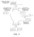
- a wavelength converter according to a second embodiment of the present invention will now be explained with reference to Figs. 2 and 3.
- the wavelength converter corresponds to the aforementioned second aspect of the present invention.
- Fig. 3 is a view for explaining wavelength conversion procedures of lightwaves in the second wavelength converter.
- a broadband multi-channel simultaneously wavelength conversion portion 10 is composed of a pump source 2, an optical combiner 3, optical fiber 4 and an optical filter 5.
- An optical filter 1 and an optical combiner 6 are both constituent of the portion 10.
- the optical filter 1 is a Fabry-Perot etalon filter in this embodiment and transmittance of the filter 1 has its peaks periodically in 2 channels spacing in wavelength domain.
- the lightwaves required to be wavelength converted are combined with pump light emitted from the pump source 2 by an optical combiner 3.
- the combined lightwaves are launched into the optical fiber 4 and wavelength converted lightwaves are generated simultaneously by virtue of the FWM in the fiber 4. Solely the wavelength converted lightwaves are filtered out by the optical filter 5.
- the wavelength converted lightwaves output from the portion 10 are combined with the lightwaves required not to be wavelength converted that are outputted from the optical filter 1. Consequently, configuration of the wavelength of WDM lightwaves outputted from the wavelength converter is different from the original WDM lightwaves.
- the wavelength interval of the WDM lightwaves outputted from the wavelength converter is broader than that of the original WDM lightwaves by twice.
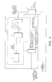
- a wavelength converter according to a third embodiment of the present invention will now be explained with reference to Figs. 4 and 5.
- Schematic of the apparatus of the wavelength converter is shown in Fig. 4.
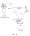
- Fig. 5 is a view for explaining wavelength conversion procedures of lightwaves in the third wavelength converter.
- a broadband multi-channel simultaneously wavelength conversion portion 10 is composed by a pump source 2, an optical combiner 3, optical fiber 4 and an optical filter 5.
- An optical filter 1 and an optical combiner 7 are both constituent of the portion 10.
- the lightwaves required to be wavelength converted are filtered out on alternate channels from the WDM lightwaves 1, and the lightwaves required to be wavelength-converted are combined with pump light from the pump source 2 by an optical combiner 3.
- the combined lightwaves are launched into the optical fiber 4 and wavelength converted lightwaves are generated by four-wave mixing (FWM) in the fiber.
- Output lightwaves from the optical fiber 4 is launched into the optical filter 5 and solely the wavelength converted lightwaves are outputted from the filter 5.
- the end of the other output port of the optical filter 1 is anti-reflection coated not to output the lightwaves required not to be wavelength converted.
- the wavelength converted lightwaves and externally launched WDM lightwaves 2 are combined with by the optical combiner 7 to reconfigure alternative WDM lightwaves in wavelength domain. Concerning the wavelength conversion, it should be remarked that any wavelength of the wavelength converted lightwaves must not be coincided with all the wavelength of the launched WDM lightwaves.
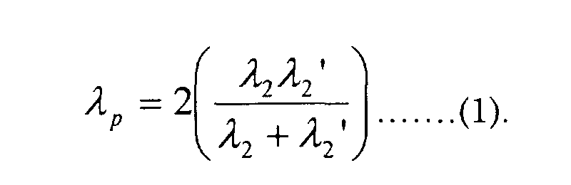
- the wavelength of the pump light ⁇ p generated from the pump source 2 shown in Fig. 4 is determined by the frequency phase-matching condition (or equivalently energy conservation law) among the a constituent of the WDM lightwaves 2 whose wavelength is ⁇ 2 and wavelength of the corresponding wavelength converted lightwave ⁇ 2 that is predetermined from the knowledge of the system design.
- the result is as follows, From the requirement of the propagation constant phase-matching condition (or equivalently momentum conservation law), zero-dispersion wavelength of the optical fiber 4 must be in the vicinity of the ⁇ p represented in equation (1).
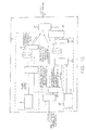
- FIG. 6 Schematic of the apparatus of the wavelength converter is shown in Fig. 6.
- Figs. 7 and 8 show schematic of examples of the optical cross connect based on WDM systems.
- the wavelength converter is fourth aspect of the present invention.
- Each wavelength of the 6-channels WDM signals is put to be ⁇ 1 to ⁇ 6 respectively.
- All the signals are demultiplexed into wavelength from ⁇ 1 to ⁇ 6 by the optical demultiplexer located into the A side in Fig. 7.
- the configuration will be referred as the original configuration.
- the system supplies the first and fourth channels' information to the customers in the direction C.
- the information carried by the third and sixth channels (corresponding to the signal wavelength ⁇ 3 and ⁇ 6 ) are transmitted to the direction C instead of the information carried by the signals in ⁇ 1 and ⁇ 4 in original configuration.
- the requirements can not be achieved straightforwardly solely changing the arrangement of the optical demultiplexer because the optical multiplexer is designed and fabricated to made the best performance for transmitting the lightwaves in ⁇ 1 and ⁇ 4 , and the other devices and components have the same circumstances, e.g. , optical amplifier, receiver and so on, are optimized to process the lightwaves in ⁇ 1 and ⁇ 4 .
- One of the best solutions to achieve the above requirements is to convert the wavelength from ⁇ 3 and ⁇ 6 to the wavelength ⁇ 1 and ⁇ 4 respectively before demultiplexing the lightwaves by the optical demultiplexer.
- the wavelength converter shown in Fig. 6 enables us to realize the above wavelength conversion. Consequently, the problem can be resolved by setting the wavelength converter 50 shown in Fig. 6 to the optical cross connect as shown in Fig. 8.
- a function of the wavelength converter 50 shown in Fig. 6 will be described as follows with help of Fig. 9.
- a view for explaining wavelength conversion procedures of lightwaves in the wavelength converter is shown in Fig. 9.
- the six channels WDM lightwaves are launched into the input port 11.
- the third and sixth channels (corresponding to the wavelength ⁇ 3 and ⁇ 6 ) are filtered out. Namely the third information carried by the lightwave in ⁇ 3 and the sixth information carried by the lightwave in ⁇ 6 are both filtered out and outputted from the one output port of the filter 1.
- the lightwaves ⁇ 3 and ⁇ 6 (of course and the third and sixth information) are divided respectively by the optical divider 14.
- Output lightwaves from the one port of the optical divider 14 is launched into an optical amplifier 15, and the amplified lightwaves and the remained lightwaves (ch. 1, ch. 2, ch. 4 and ch. 5) are multiplexed by an optical multiplexer 16.
- the WDM lightwaves obtained by the procedures are transmitted toward the transmission port 17 of the wavelength converter shown in Fig. 6.
- Lightwaves of the channel 3 and 6 outputted from the other end of the optical divider 14 are wavelength converted by the first multi-channels simultaneous wavelength conversion portion 10. As shown in Fig.
- the first multi-channels simultaneous wavelength conversion portion 10 is composed of the optical combiner 3, pump light source 2 whose wavelength ⁇ p1 is longer than the ⁇ 6 , optical fiber 4 whose zero-dispersion wavelength is in the vicinity of ⁇ p1 and the optical filter 5 whose transmittance is large inside the longer wavelength region than ⁇ p1 .
- the third and sixth information, each is carried by the lightwave of the wavelength ⁇ 3 and ⁇ 6 are wavelength converted to the lightwave of the wavelength ⁇ 3 ' and ⁇ 6 ' respectively without lack of the information.
- the next procedure is the wavelength conversion from the wavelength converted lightwaves in wavelength ⁇ 3 ' and ⁇ 6 ' obtained by the first multi-channels simultaneous wavelength converter 10, to the wavelength ⁇ 1 and ⁇ 4 respectively by use of the second multi-channels simultaneous wavelength conversion portion 20.
- the second multi-channels simultaneous wavelength converter 20 is composed of a second optical combiner 21, a second pumping source 22 whose wavelength is ⁇ p2 , a second optical fiber 23 whose zero-dispersion wavelength is in the vicinity of ⁇ p2 , and a second optical filter 24 whose transmittance is large inside the longer wavelength region than ⁇ p2 .
- the third and sixth information each is carried by the lightwave of the wavelength ⁇ 3 and ⁇ 6 at the input port 11 of the wavelength converter 10 are wavelength converted to the lightwave of the wavelength ⁇ 1 and ⁇ 4 respectively and outputted from the output port of the optical combiner 27 without lack of the information.
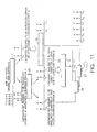
- FIG. 11 is a diagram for explaining wavelength conversion procedures of lightwaves in the fifth wavelength converter shown in Fig. 10.
- the filtered out lightwaves are combined with pump light from the pump source 2 by an optical combiner 3 and the lightwaves outputted from the combiner 3 are launched into the optical fiber 4.
- Wavelength converted lightwaves are generated by the FWM in the fiber.
- Output lightwaves from the fiber 4 are launched into the optical filter 5 and solely the wavelength converted lightwaves are outputted. Consequently, the filtered out lightwaves from the optical filter 1 are wavelength converted in the first wavelength conversion portion 10.
- the remained lightwaves not to be filtered out by the optical filter 1 are launched into a second Fabry-Perot etalon filter 25.
- the etalon filter 25 has the specification almost similar with the optical filter 1 except the wavelength of the transmittance peak is shifted 1-channel frequency interval of the original WDM lightwaves.
- the lightwaves inputted to the etalon filter 25 is filtered out and the WDM lightwaves whose frequency interval corresponds to the 2-channels spacing of the original WDM lightwaves are outputted from the each two-output port of the filter 25.
- the filtered out lightwaves are combined with the pump light from the second pump source 21 by an optical combiner 22.
- the combined lightwaves are launched into the second optical fiber 23 and wavelength converted lightwaves are generated by FWM in the optical fiber 23.
- the optical filter 24 solely the wavelength converted lightwaves are outputted.
- the filtered out lightwaves from the optical filter 25 are simultaneously wavelength converted by the multi-channel simultaneous wavelength conversion portion 20.
- the remained lightwaves from the filter 25 not to be wavelength converted are combined with the wavelength converted lightwaves outputted from the multi-channels simultaneous wavelength conversion portion 20 by an optical combiner 26.
- the combined WDM lightwaves are further combined with the wavelength converted lightwaves outputted from the multi-channels simultaneous wavelength converter 10 by an optical wavelength combiner 27.
- Channel arrangement of the finally combined lightwaves outputted from the wavelength combiner 27 is reconfigured in comparison of the original WDM lightwaves in wavelength domain by the wavelength converter provided in this embodiment.
- more general case namely the case where Nis an arbitrary integer, can be realized straightforwardly as follows.
- the channel number of the input (or original) WDM lightwaves is K composed of the lightwaves whose wavelength are ⁇ 1 , ⁇ 2 , ...., ⁇ K and the frequency interval of the K -channel lightwaves are set to be ⁇ f
- the WDM lightwaves with i ⁇ f frequency spacing can be realized by applying the two Fabry-Perot etalon filters to each optical filters of the first optical filter 1 and the second filter 25 shown in Fig. 10. Wavelengths of the lightwaves that are filtered out from the first Fabry-Perot etalon filter 1, are put to be ⁇ 1 ', ⁇ 2 ', ⁇ 3 ', ..., ⁇ m ', from the short wavelength side where m is an integer. The lightwaves will be launched into the multi-channels simultaneous wavelength conversion portion 10.
- wavelengths of the lightwaves that are filtered out from the second Fabry-Perot etalon filter 25, are put to be ⁇ 1 ", ⁇ 2 ", ⁇ 3 ", ..., ⁇ m ", from the short wavelength side.
- the lightwaves will be launched into the multi-channels simultaneous wavelength conversion portion 20.
- Wavelengths of the lightwaves that are not filtered out from neither the first 1 nor the second Fabry-Perot etalon filter 25, are put to be ⁇ 10 , ⁇ 20 , ⁇ 30 , ..., ⁇ m0 , from the short wavelength side.
- the lightwaves will be combined with the wavelength converted lightwaves outputted from the wavelength conversion portion 20 by an optical combiner 26.
- the wavelength of the first pump light to be the lightwaves whose wavelength are ⁇ 1 ', ⁇ 2 ',...., ⁇ m ' are wavelength converted to the wavelength ⁇ 1C ', ⁇ 2C ',...., ⁇ mC '.
- the second pump light from the second pump source 21 lightwaves whose wavelength are ⁇ 1 ", ⁇ 2 ",...., ⁇ m " are wavelength converted to the wavelength ⁇ 1C ", ⁇ 2C ",...., ⁇ mC " under the condition that the wavelength ⁇ mC " satisfies the inequality ⁇ 1C ' ⁇ ⁇ mC ".
- Fig. 12 is a schematic of the wavelength converter, hereafter referred as the "sub-band converter”.
- Fig. 13 is a conceptual schematic to explain the sub-band that is the fundamental concept to explain the present invention.
- 20-channels WDM lightwaves are schematically represented. At present, more than 128 channels of the WDM transmission experiments were demonstrated. Concerning the signal processing of such an extraordinarily number of the channels, the difficulties of the system management increase monotonically as the channel number increases. To resolve the difficulties sub-band management is considered as follows.
- FIG. 14 Schematic of an example of the optical cross connect using the sub-band is shown in Fig. 14.
- WDM lightwaves are transmitted in the direction from A to B.
- the WDM lightwaves and therefore the information carried by the lightwaves in sub-band ⁇ 2 is divided by an optical divider and dropped in the direction to C.
- the information carried by the sub-band ⁇ 2 is desired to be changed to the information carried by the sub-band ⁇ 3 , and transmit to the direction C instead of the information carried by the sub-band ⁇ 2 .
- the system design of the direction C is optimized for processing the WDM lightwaves in sub-band ⁇ 2 , the above change could not be realized straightforwardly e.g.
- the problem is essentially equivalent to the fourth-embodiment of the present invention and is solved solely replacing the channel wavelength converter to the sub-band converter.
- the sub-band converter changes the wavelength of the sub-band from ⁇ 2 to ⁇ 3 , or equivalently wavelength of the lightwaves ⁇ 2S , ⁇ 21 , ... ⁇ 2L , to the ⁇ 3L ,.... ⁇ 31 , ⁇ 3S .
- Inserting the sub-band converter into the system shown as in Fig. 15, and changing the optical divider position from the line of ⁇ 2 to the line of ⁇ 3 the problem can be resolved.
- the optical divider set at the line of ⁇ 3 should be optimized to process the lightwaves inside the side-band ⁇ 3 .
- Fig. 12 Schematic of the sub-band converter is shown in Fig. 12 and the diagram for explaining wavelength conversion procedures of lightwaves is shown in Fig. 16. All twenty channels of the WDM lightwaves are launched into the input port 30 in Fig. 12. Solely sub-band ⁇ 3 is filtered out from the input WDM lightwaves by a dielectric multi-layered filter 1 whose transmittance peak covers whole of the wavelength region ⁇ 3 in the wavelength domain. The filtered out lightwaves (lightwaves inside the sub-band ⁇ 3 ) are combined with pump light from a pump source 2 by an optical combiner 3. The combined lightwaves are launched into the optical fiber 4 and wavelength converted lightwaves are generated by the FWM in the optical fiber 4.
- the information carried by the lightwaves of the sub-band ⁇ 3 at the input end of the sub-band converter are carried by the lightwaves in sub-band ⁇ 2 after the sub-band converter by virtue of the sub-band wavelength conversion.
- the sub-band converter is composed of the pump source 2 whose wavelength is coincided with the value of equation (7), an optical fiber 4 whose zero-dispersion wavelength is in the vicinity of the value provided in equation (7), dielectric multi-layered filter 1 whose transmittance peak is coincided with the wavelength inside the sub-band ⁇ 3 in the wavelength domain and an optical filter 5 whose transmittance peak is coincided with all the wavelength inside the sub-band ⁇ 2 in the wavelength domain.
- the peak transmittance value is much larger than the transmittance value at the sub-band ⁇ 2 in the wavelength domain.
- the output lightwaves from the optical filter 5 are outputted from the output port 31.
- the sub-band converter enables to transfer the information carried by sub-band ⁇ 3 at point A in Fig. 15 to the direction C by changing the wavelength of the lightwaves to be coincided with inside the sub-band ⁇ 2 .
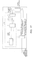
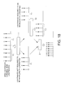
- Fig. 18 is a diagram for explaining wavelength conversion procedures of lightwaves in the wavelength converter shown in Fig. 17.
- the embodiments 2, 4 and 5 the embodiment allows to output the WDM lightwaves whose channel interval is narrower than the input WDM lightwaves.
- dielectric multi-layered filter is adopted as the optical filter 1.
- sub-band ⁇ 2 shown in Fig. 18 can be filtered out.
- Frequency interval of the WDM lightwaves shown in Fig. 8 is constant.
- lightwaves in the sub-band ⁇ 2 are filtered out from the input WDM lightwaves shown in Fig. 18 by a dielectric multi-layered filter 1.
- the filtered out lightwaves inside the sub-band ⁇ 2 is combined with the pump light from the pump source 2 by an optical combiner 3.
- the combined lightwaves are launched into the optical fiber 4 and wavelength converted lightwaves inside the sub-band ⁇ 2 ' are generated by FWM in the fiber 4. Solely the sub-band ⁇ 2 ' is filtered out by an optical filter 5.
- wavelength converted lightwaves inside the sub-band ⁇ 2 ' outputted from the optical filter 5 are interleaved between the each channel of the lightwaves inside the sub-band ⁇ 1 which were not filtered out from the dielectric multi-layered filter 1.
- frequency interval of the output WDM lightwaves is half of the input WDM lightwaves.
- the technique is applicable to make full use of the transmission capacity of the optical fibers in the following sense. Concerning the cross connect between the two different transmission lines.
- One is composed of a kind of optical fiber capable to realize higher-spectral efficiency that is little influenced by inter-channel crosstalk than the other transmission line composed of the other type of the fiber.
- the former is referred as the high-quality line and the latter is referred as the low-quality line.
- the advantage of the high-quality line is wasted.
- the wavelength converter provided in the embodiment enables to convert the WDM signals from the low-spectral efficiency to the high-spectral efficiency.
- the advantage of the high-quality line can be used more efficiently in comparison of the above directly transferring method.
- Wavelength of the pump light ⁇ p from the pump source 2 shown in Fig. 17, must be satisfied with the following condition: ⁇ 4 ⁇ ⁇ p ⁇ ⁇ 5
- Fig. 19 shows an optical demultiplexing module according to an eighth embodiment of the present invention.
- the optical demultiplexing module corresponds to the aforementioned eighth aspect of the present invention.
- the optical demultiplexing module is composed of the wavelength converter 35 that can broaden the frequency interval of the input lightwaves (as described in the second and fifth embodiments), and an optical demultiplexer 36.
- An arrayed waveguide grating (AWG) is one of the examples of such an optical demultiplexer.
- Typical extinction ratio of AWG is known to be 16 dB at frequency interval 27 GHz. It is known that the extinction ratio can be increased as the frequency interval becomes large in generally.
- the wavelength converter 35 is applicable to enhance the extinction ratio of the AWG 36 by concatenating with the optical demultiplexer 36.
- the frequency interval of the input lightwaves is broadened by the wavelength converter 35.
- the extinction ratio of the AWG 36 concatenated with after the wavelength converter 35 is enhanced.
- the optical demultiplexer concatenated with the wavelength converter 35 becomes an optical demultiplexing module with low crosstalk.
- Fig. 20 shows a wavelength converter according to a ninth embodiment of the present invention.
- the wavelength converter provides another application of the aforementioned seventh aspect of the present invention.
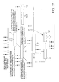
- Fig. 21 is a view for explaining wavelength conversion procedures of lightwaves in the wavelength converter shown in Fig. 20.
- Both the wavelength conversion portion 10 and 20 shown in Fig. 20 can expand the frequency interval of the WDM lightwaves inputted to the each portion as described in the second and fifth embodiments of the present invention.
- the frequency interval expansion ratio can be realized to be 1/( n +1) for an arbitrary positive integer n by applying the technique shown in the fifth embodiment discussed as follows.
- the first optical filter 1 is a dielectric multi-layered filter.
- the first lightwaves required to be wavelength converted are filtered out from the optical filter 1.
- the first lightwaves required to be wavelength converted are combined with the pump light from the pump source 2 by an optical combiner 3.
- the combined lightwaves are launched into an optical fiber 4.
- the first wavelength converted lightwaves are generated by FWM in optical fiber 4. Only the first wavelength converted lightwaves are filtered out from the output lightwaves from the optical fiber 4 by an optical filter 6.
- the lightwaves not to be filtered out by the first dielectric multi-layered filter 1 are launched into the second dielectric multi-layered filter 25.
- Second lightwaves required to be wavelength converted are filtered out by the filter 25 and combined with pump light from the pump source 21 by an optical combiner 22.
- the combined lightwaves outputted from the optical combiner 22 are launched into an optical fiber 23 and wavelength converted lightwaves are generated by FWM in the fiber 23. Solely the second wavelength converted lightwaves can be filtered out from the output lightwaves from the fiber 23 by use of the optical filter 24.
- the second wavelength converted lightwaves are combined with the lightwaves not required to be secondly wavelength converted by the wavelength conversion portion 20, by an optical combiner 26.
- the combined WDM lightwaves outputted from the optical combiner 26 are further combined with the first wavelength converted lightwaves output from the optical filter 6 by an optical combiner 27 in Fig. 20.
- the result can be extended to more general case (equivalently arbitrary positive integer n ) straightforwardly.
- Fig. 22 shows a wavelength converter according to a tenth embodiment of the present invention.
- the wavelength converter corresponds to the aforementioned ninth aspect of the present invention.
- a broadband mulch-channel simultaneous wavelength conversion portion 10 is composed of a pump source 2, an optical combiners 3, an optical fiber 4 for generating the FWM and an optical filter 5.
- the optical fiber 4 can be replaced to be an SOA.
- Fig. 23 is a view for explaining wavelength conversion procedures of lightwaves in the wavelength converter shown in Fig. 22.
- Frequency interval of the WDM lightwaves inputted to the wavelength converter is constant.
- the input WDM optical lightwaves are divided into two by an optical divider 37.
- One of the divided WDM lightwaves is the lightwaves required to be wavelength converted and is combined with a pump light from the pump source 2 by an optical combiner 3.
- the combined lightwaves outputted from the optical combiner 3 are launched into the optical fiber 4 and wavelength converted lightwaves are generated by FWM. Solely the wavelength converted lightwaves are filtered out from the output lightwaves from the optical fiber 4 by the optical filter 5.
- the lightwaves required to be wavelength converted that is outputted from the optical divider 37 are wavelength converted by the broadband multi-channels simultaneous wavelength conversion portion 10.
- Lightwaves not required to be wavelength converted are outputted from the other port of the optical divider 37 and are combined with the wavelength converted lightwaves from optical filter 5 by the optical combiner 6 without duplication in wavelength domain.
- the combined lightwaves are outputted from the wavelength converter. Then we can increase the channel numbers twice in comparison of the original WDM lightwaves.
- Y channel WDM optical lightwaves ( Y is an arbitrary positive integer) are considered as the input WDM lightwaves (referred as the original WDM lightwaves).
- the wavelength of the Y -th lightwave which is a constituent of the original WDM lightwaves is put to be ⁇ Y
- ⁇ Y is the longest wavelength of the original WDM lightwaves.
- the WDM lightwaves composed of the lightwaves whose wavelength are ⁇ 1 , ⁇ 2 , ..., ⁇ Y are wavelength converted to the lightwaves whose wavelength are ⁇ Y ', ⁇ Y-1 ', ..., ⁇ 1 '.
- wavelength ⁇ Y ' is the shortest wavelength among the wavelength converted lightwaves.
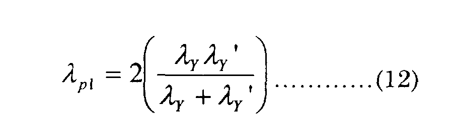
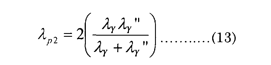
- Wavelength of the pump light is determined by the frequency phase-matching condition and is represented as The condition and the propagation constant phase-matching condition imply that the zero-dispersion wavelength of the optical fiber 4 is in the vicinity of the ⁇ p .
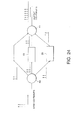
- Fig. 24 shows a wavelength converter according to an eleventh embodiment of the present invention.
- the wavelength converter corresponds to the aforementioned ninth to eleventh aspect of the present invention.
- the wavelength converter appeared in Fig. 24 is an example of the applications of the tenth embodiment.
- Concerning the WDM lightwaves inputted to the optical divider 40 (referred to be the original WDM lightwaves hereafter in this embodiment), wavelength of the lightwaves are put to be ⁇ 1 , ⁇ 2 , ..., ⁇ Y , where Y is a positive integer.
- the original WDM lightwaves are divided into three using e . g ., an optical star-coupler.
- the divided lightwaves outputted from the first output port of the optical divider 40 is the WDM lightwaves not required to be wavelength converted.
- Output lightwaves from the remained port are both the WDM lightwaves required to be wavelength converted.
- the lightwaves are wavelength converted by the broadband multi-channels simultaneously wavelength conversion portion 10 and 20 respectively. Both the wavelength converted lightwaves outputted from the wavelength conversion portion 10 and 20 are combined with the WDM lightwaves outputted from the first output port of the optical divider 40 by an optical combiner 41.
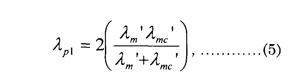
- wavelength of the original WDM lightwaves are put to be ⁇ 1 , ⁇ 2 , ..., ⁇ Y , where Yis a positive integer. Then putting the wavelength of the wavelengths converted lightwaves outputted from the first broadband multi-channels wavelength conversion portion 10 wavelength as ⁇ Y ', ⁇ Y-1 ', ..., ⁇ 1 ', the wavelength ⁇ Y ' is the shortest in all of the first wavelength converted lightwaves.
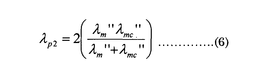
- Pump wavelength of the first wavelength portion ( ⁇ p1 ) and second wavelength portion ( ⁇ p2 ) is determined by the frequency phase-matching condition and are provided as From the propagation constant phase-matching condition, zero-dispersion wavelength of the optical fiber in the first and second wavelength conversion portion must be in the vicinity of the ⁇ p1 and ⁇ p2 respectively.
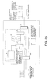
- Fig. 25 shows a wavelength converter according to a twelfth embodiment of the present invention.
- the wavelength converter corresponds to an alternation of the aforementioned sixth aspect of the present invention.
- lightwaves required to be wavelength converted are filtered out from the WDM lightwaves inputted to the wavelength converter (referred to be the original lightwaves, hereafter in this embodiment) by an optical band-pass filter 37.
- the filtered out WDM lightwaves are constituents of the original WDM lightwaves and are equivalent to the sub-band of the original WDM lightwaves from the analogy of the concept of the sub-band as shown in the sixth embodiment of the document.
- the filtered out sub-band is wavelength converted simultaneously by use of the FWM in the optical fiber 4. According to the Fig.
- the filtered out lightwaves in the sub-band is the lightwaves required to be wavelength converted, and are combined with the pump light from the pump source 2 by an optical combiner 3.
- the combined lightwaves are launched into the optical fiber 4 and the wavelength converted lightwaves are generated by FWM in the fiber 4. Solely the wavelength converted lightwaves are filtered out from the lightwaves output from the optical fiber 4 by an optical filter 5. Consequently, the lightwaves required to be wavelength converted that are outputted from the optical filter 37, are simultaneously wavelength converted by the wavelength conversion portion 10.
- the wavelength converted lightwaves outputted from the wavelength conversion portion 10 are combined with the lightwaves not required to be wavelength converted that are outputted from the optical filter 37, by an optical combiner 6 without duplication in wavelength domain.
- the combined lightwaves are outputted from the wavelength converter.
- one sub-band of the original WDM lightwaves is wavelength converted simultaneously to the outside of the full band of the original WDM lightwaves in the wavelength domain by the wavelength converter described in this embodiment.
- the optical fiber 4 shown in Fig. 25 can be replaced to an SOA.
- Fig. 26 shows an embodiment of a wavelength-division multiplexing method corresponding to the aforementioned twelfth to fourteenth aspect of the method in the present invention.
- a trunk line is composed of the conventional single-mode fiber (referred as SMF hereafter) and dispersion compensating fibers, e.g ., Reverse-Dispersion Fiber (referred as RDF hereafter).
- SMF single-mode fiber
- RDF Reverse-Dispersion Fiber
- Efficiency of the so-called transmission line composed of the Dispersion Managed line (referred as DM line hereafter), e.g. , transmission line composed of the SMF and RDF, are verified experimentally. Under the optimized design of the DM line, the transmission line can suppress the noise from the inter-channel crosstalk due to inter-channel FWM.
- the transmission line composed of the conventional dispersion-shifted fiber (referred as DSF line hereafter) that is more influenced by the FWM than the DM line, are sometimes used in the metropolitan area network since the metropolitan area network is not required such a high-capacity transmission in comparison of the trunk line.
- DSF line the transmission line composed of the conventional dispersion-shifted fiber
- the frequency interval of the WDM signals transmitted in the metropolitan area network are broader than the interval of the trunk line, and furthermore the bit-rate of the signals per channel is smaller than the bit-rate of the trunk line.
- the WDM signals transmitted to the trunk line cannot be dropped to the metropolitan line directly with preserving the frequency intervals of the WDM signals.
- the inter-channel FWM will deteriorate the signal to noise ratio because of the difference of the influence of the crosstalk due to FWM.
- the wavelength converter provided in the aforementioned fourth and fifth aspects of the present invention resolve the problem.
- the wavelength converter provided the fourth and fifth aspects of the present invention can broaden the frequency interval of the WDM signals inputted to the wavelength converter.
- the wavelength converter provided in the aforementioned sixth and seventh aspects of the present invention can reduce the frequency interval of the WDM signals input to the wavelength converter.
- the wavelength converter provided the sixth and seventh aspects of the present invention can reduce the frequency interval of the WDM signals input to the wavelength converter.
- the influences of the FWM induced inter-channel crosstalk is increased as large as the DM line (SMF+RDF in Fig. 26) can compensate for.
- An optical add-drop multiplexer/demultiplexer (OADM) applicable to connect the trunk line and the metropolitan area network can realize the above two functionality.
- the wavelength converter provided in the second or sixth embodiment (or sixth or ninth embodiment) can connect the trunk line and the metropolitan area network by avoiding the problems discussed above.
- OXC is used as an acronym of the Optical Cross Connect.
- the wavelength converter according to the present invention has the following effects:
- the wavelength-division multiplexing transmission method according to the present invention has the following effects:
Landscapes
- Physics & Mathematics (AREA)
- Engineering & Computer Science (AREA)
- Computer Networks & Wireless Communication (AREA)
- Signal Processing (AREA)
- Nonlinear Science (AREA)
- Electromagnetism (AREA)
- General Physics & Mathematics (AREA)
- Optics & Photonics (AREA)
- Optical Communication System (AREA)
- Optical Modulation, Optical Deflection, Nonlinear Optics, Optical Demodulation, Optical Logic Elements (AREA)
Abstract
Description


In Fig. 17, lightwaves in the sub-band Λ 2 are filtered out from the input WDM lightwaves shown in Fig. 18 by a dielectric multi-layered filter 1. The filtered out lightwaves inside the sub-band Λ 2 is combined with the pump light from the pump source 2 by an optical combiner 3. The combined lightwaves are launched into the optical fiber 4 and wavelength converted lightwaves inside the sub-band Λ2 ' are generated by FWM in the fiber 4. Solely the sub-band Λ 2 ' is filtered out by an optical filter 5.

The optical fiber 4 shown in Fig. 25 can be replaced to an SOA.
Claims (14)
- A wavelength converter using four-wave mixing (FWM) in optical fibers or semiconductor optical amplifier (SOA), wherein:
One or more optical lightwaves are filtered out from wavelength-division multiplexed (WDM) lightwaves inputted to the wavelength converter by an optical component that has the filtering functionality in frequency domain, and solely the filtered out lightwaves are wavelength converted. - A wavelength converter according to claim 1, wherein solely the filtered out lightwaves from the WDM source inputted to the wavelength converter is wavelength converted by FWM, and the wavelength converted lightwaves are combined with the lightwaves neither to be filtered out nor to be wavelength converted, and provide an alternative channel configuration of the WDM lightwaves to the WDM lightwaves inputted to the wavelength converter in wavelength domain.
- A wavelength converter according to claim 1, wherein solely the filtered out lightwaves from the WDM source inputted to the wavelength converter is wavelength converted by FWM, and the wavelength converted lightwaves are combined with the one or more lightwaves any of those wavelength are not coincided with all the wavelength of the converted lightwaves, and provide an alternative channel configuration of the WDM lightwaves to the WDM lightwaves inputted to the wavelength converter in wavelength domain.
- A wavelength converter according to any one of claims 1 to 3, wherein one or more optical components each has the filtering function to filter out one or more lightwaves in each N channels frequency spacing (N is a positive integer) from the WDM lightwaves inputted to the optical component, is used as the optical component, and the lightwaves filtered out by each components are wavelength converted independently or simultaneously by use of the FWM.
- A wavelength converter according to claim 4, wherein N optical components that have the filtering function to filter out the lightwaves periodically in each N channels spacing (N is a positive integer) from the WDM lightwaves inputted to the optical component, are used as the optical component, and the filtered out lightwaves are wavelength converted simultaneously or independently by use of the FWM, and the wavelength converted WDM lightwaves are combined with the lightwaves any of whose wavelength are not coincided with all the wavelength of the wavelength converted lightwaves, and the frequency interval of the resultant WDM lightwaves is broadened in comparison with the frequency interval of the WDM lightwaves inputted to the wavelength converter.
- A wavelength converter according to any one of claims 1 to 3, wherein optical components having the filtering functionality are used to filter out one or more clusters of the WDM lightwaves in the wavelength domain (sub-bands) that are constituents of the WDM lightwaves inputted to the wavelength converter, and one or more sub-bands are wavelength converted simultaneously or independently by use of the FWM.
- A wavelength converter according to claim 6, wherein WDM lightwaves inputted to the wavelength converter is virtually divided into n (n is a positive integer), and n-1 optical component having the filtering functionality is used to filter out j-th sub-band (j is an arbitrary positive integer in each optical component which satisfies the condition j≦n) of the WDM lightwaves (sub-band) that is a constituent of the entire-band of the WDM lightwaves inputted to the wavelength converter, and the each sub-band is wavelength converted simultaneously or independently by use of the FWM, and all the wavelength converted lightwaves are then combined to obtain a WDM lightwaves whose configuration in wavelength domain is different from the WDM lightwaves inputted to the wavelength converter, and the frequency interval of the resultant WDM lightwaves is reduced in comparison of the frequency interval of the input WDM lightwaves.
- A wavelength converter wherein:
an optical demultiplexing device is connected after the wavelength converter according to claim 4 and 5 to demultiplex the WDM lightwaves with high extinction ratio, thereby providing an enhanced optical demultiplexing module in comparison of the optical demultiplexing device. - A wavelength converter using four-wave mixing (FWM) in an optical fiber or a semiconductor optical amplifier, wherein:
input WDM lightwaves are divided into two or more lightwaves by an optical divider, and one or two or more lightwaves outputted from the output port of the divider are wavelength converted. - A wavelength converter according to claim 9, wherein some outputted lightwaves from the output port of the optical divider are wavelength converted by FWM, and the wavelength converted lightwaves and the outputted lightwaves from the remained output port are combined with by an optical combiners to obtain WDM lightwaves whose configuration in wavelength domain, is different from the configuration of the input WDM lightwaves.
- A wavelength converter according to claim 9, wherein some outputted lightwaves from the output port of the optical divider are wavelength converted by FWM, and the wavelength converted lightwaves and the WDM lightwaves all of whose wavelength are different from any of the wavelength converted light, are combined with by an optical combiners to obtain WDM lightwaves whose configuration in wavelength domain, is different from the configuration of the input WDM lightwaves.
- A wavelength-division multiplexing transmission method wherein:
output WDM signals from the wavelength converter whose frequency interval is broaden in comparison of the WDM signals input to the wavelength converter is obtained by using the wavelength converter according to claim 4 or 5, and the output WDM signals is transferred from the transmission line less influenced by the inter-channel crosstalk to the transmission line strongly influenced by the crosstalk. - A wavelength-division multiplexing transmission method wherein:
output WDM signals from the wavelength converter whose frequency interval is reduced in comparison of the WDM signals input to the wavelength converter is obtained by using the wavelength converter according to claim 6 or 7, and the output WDM signals is transferred from the transmission line strongly influenced by the inter-channel crosstalk to the transmission line less influenced by the crosstalk. - A wavelength-division multiplexing transmission method according to claim 13 wherein:
the wavelength bands with no WDM signals that are realized as a result of wavelength converter described in claim 13, are used to add external WDM signals any of whose wavelength are not coincided with all of the wavelength of the wavelength converted signals, by combining the two WDM signals, and the combined WDM signals are transmitted.
Applications Claiming Priority (4)
| Application Number | Priority Date | Filing Date | Title |
|---|---|---|---|
| JP37481399 | 1999-12-28 | ||
| JP37481399 | 1999-12-28 | ||
| JP2000303512 | 2000-10-03 | ||
| JP2000303512A JP4875237B2 (en) | 1999-12-28 | 2000-10-03 | Wavelength division multiplex transmission method using wavelength converter |
Publications (2)
| Publication Number | Publication Date |
|---|---|
| EP1113613A2 true EP1113613A2 (en) | 2001-07-04 |
| EP1113613A3 EP1113613A3 (en) | 2005-06-08 |
Family
ID=26582627
Family Applications (1)
| Application Number | Title | Priority Date | Filing Date |
|---|---|---|---|
| EP00311736A Withdrawn EP1113613A3 (en) | 1999-12-28 | 2000-12-28 | Wavelength converting apparatus and wavelength division multiplexing system using same |
Country Status (3)
| Country | Link |
|---|---|
| US (1) | US6665113B2 (en) |
| EP (1) | EP1113613A3 (en) |
| JP (1) | JP4875237B2 (en) |
Cited By (5)
| Publication number | Priority date | Publication date | Assignee | Title |
|---|---|---|---|---|
| GB2370650A (en) * | 2000-09-21 | 2002-07-03 | Ilotron Ltd | Optical multicasting |
| EP1248336A3 (en) * | 2001-03-30 | 2005-01-12 | The Furukawa Electric Co., Ltd. | Method and apparatus for wavelength conversion |
| EP3547574A1 (en) * | 2018-03-28 | 2019-10-02 | Fujitsu Limited | Wavelength division multiplex transmission apparatus and method |
| CN110582953A (en) * | 2017-04-28 | 2019-12-17 | 富士通株式会社 | Transmission device and transmission method |
| EP3706343A1 (en) * | 2019-02-25 | 2020-09-09 | Fujitsu Limited | Transmitting device and transmission system |
Families Citing this family (39)
| Publication number | Priority date | Publication date | Assignee | Title |
|---|---|---|---|---|
| US7061664B2 (en) * | 1999-12-28 | 2006-06-13 | The Furukawa Electric Co., Ltd. | Wavelength converter and wavelength division multiplexing transmission method using the same |
| US7054057B2 (en) * | 2001-03-27 | 2006-05-30 | The Furukawa Electric Co., Ltd. | Multi-frequency light source |
| JP2002315027A (en) * | 2001-04-18 | 2002-10-25 | Nec Corp | Wavelength group wavelength converter and wavelength group switch using the same |
| US6980743B1 (en) * | 2001-05-18 | 2005-12-27 | Juniper Networks, Inc. | Transparent wavelength division multiplexing |
| US7187868B2 (en) * | 2001-07-30 | 2007-03-06 | Pirelli Cavi E Sistemi S.P.A., | Wavelength division multiplexing optical transmission system using a spectral inversion device |
| US20040052530A1 (en) * | 2002-09-17 | 2004-03-18 | Cechan Tian | Optical network with distributed sub-band rejections |
| US20040212872A1 (en) * | 2003-03-25 | 2004-10-28 | Jean-Luc Auge | Optical signal processing system and method |
| US7558485B2 (en) * | 2003-05-20 | 2009-07-07 | Alcatel-Lucent Usa Inc. | Processes and systems involving optical phase conjugators |
| US20040234275A1 (en) * | 2003-05-20 | 2004-11-25 | Aref Chowdhury | Process for optical communication and system for same |
| JP2005017385A (en) * | 2003-06-23 | 2005-01-20 | Fujitsu Ltd | Dispersion compensator |
| US7483636B2 (en) * | 2003-07-28 | 2009-01-27 | Fujitsu Limited | Optical network with sub-band rejection and bypass |
| TW594109B (en) * | 2003-09-18 | 2004-06-21 | Ind Tech Res Inst | Wavelength converter with wideband four-wave-mixing |
| US20050095001A1 (en) * | 2003-10-29 | 2005-05-05 | Fujitsu Limited | Method and system for increasing network capacity in an optical network |
| US7239440B2 (en) * | 2003-11-18 | 2007-07-03 | Sumitomo Electric Industries, Ltd. | Wavelength conversion apparatus |
| US7454144B2 (en) * | 2003-12-05 | 2008-11-18 | Lucent Technologies Inc. | Low total excursion dispersion maps |
| US7522786B2 (en) | 2005-12-22 | 2009-04-21 | Palo Alto Research Center Incorporated | Transmitting light with photon energy information |
| US7310482B1 (en) * | 2005-01-19 | 2007-12-18 | Sprint Communications Company L.P. | Optical wavelength conversion for phase-modulated optical signals |
| US7433552B2 (en) | 2005-12-22 | 2008-10-07 | Palo Alto Research Center Incorporated | Obtaining analyte information |
| US8437582B2 (en) | 2005-12-22 | 2013-05-07 | Palo Alto Research Center Incorporated | Transmitting light with lateral variation |
| US7315667B2 (en) * | 2005-12-22 | 2008-01-01 | Palo Alto Research Center Incorporated | Propagating light to be sensed |
| US20070258717A1 (en) * | 2006-05-01 | 2007-11-08 | Masaaki Hirano | Optical device and wavelength conversion method and optical fiber suitable for them |
| US9164037B2 (en) | 2007-01-26 | 2015-10-20 | Palo Alto Research Center Incorporated | Method and system for evaluation of signals received from spatially modulated excitation and emission to accurately determine particle positions and distances |
| US8821799B2 (en) | 2007-01-26 | 2014-09-02 | Palo Alto Research Center Incorporated | Method and system implementing spatially modulated excitation or emission for particle characterization with enhanced sensitivity |
| JP4865657B2 (en) * | 2007-09-06 | 2012-02-01 | 日本電信電話株式会社 | Pulsed light generator |
| US8320983B2 (en) | 2007-12-17 | 2012-11-27 | Palo Alto Research Center Incorporated | Controlling transfer of objects affecting optical characteristics |
| US8373860B2 (en) | 2008-02-01 | 2013-02-12 | Palo Alto Research Center Incorporated | Transmitting/reflecting emanating light with time variation |
| US8629981B2 (en) | 2008-02-01 | 2014-01-14 | Palo Alto Research Center Incorporated | Analyzers with time variation based on color-coded spatial modulation |
| JP5617503B2 (en) * | 2010-09-30 | 2014-11-05 | 富士通株式会社 | Optical network repeater |
| US8723140B2 (en) | 2011-08-09 | 2014-05-13 | Palo Alto Research Center Incorporated | Particle analyzer with spatial modulation and long lifetime bioprobes |
| US9029800B2 (en) | 2011-08-09 | 2015-05-12 | Palo Alto Research Center Incorporated | Compact analyzer with spatial modulation and multiple intensity modulated excitation sources |
| JP5858465B2 (en) | 2011-12-19 | 2016-02-10 | 富士通株式会社 | Optical communication device, wavelength number measuring device, optical repeater, and wavelength number measuring method |
| JP5737364B2 (en) * | 2013-11-01 | 2015-06-17 | 富士通株式会社 | Optical transmission equipment |
| JP6096831B2 (en) * | 2015-05-18 | 2017-03-15 | 日本電信電話株式会社 | Phase conjugate optical converter and optical transmission system using the same |
| JP7106835B2 (en) * | 2017-10-06 | 2022-07-27 | 富士通株式会社 | Optical transmission device, wavelength conversion device, optical transmission method, and wavelength conversion method |
| JP7035548B2 (en) * | 2018-01-18 | 2022-03-15 | 富士通株式会社 | Transmission system and transmission method |
| JP7099045B2 (en) * | 2018-05-18 | 2022-07-12 | 富士通株式会社 | Wavelength converters, transmissions, and transmission systems |
| US11438086B2 (en) * | 2020-01-21 | 2022-09-06 | Fujitsu Limited | Optical amplification in an optical network |
| US11588557B2 (en) * | 2021-03-02 | 2023-02-21 | Nucript LLC | Apparatus and method for shifting a frequency of an optical signal |
| JP2024093168A (en) | 2022-12-27 | 2024-07-09 | 富士通株式会社 | Optical communication device and transmission control method |
Family Cites Families (16)
| Publication number | Priority date | Publication date | Assignee | Title |
|---|---|---|---|---|
| JP2594193B2 (en) * | 1991-10-07 | 1997-03-26 | 日本電信電話株式会社 | Optical frequency add / drop circuit |
| JP3284659B2 (en) * | 1993-04-09 | 2002-05-20 | 株式会社フジクラ | Optical switching device for WDM optical communication |
| US5386314A (en) * | 1993-09-10 | 1995-01-31 | At&T Corp. | Polarization-insensitive optical four-photon mixer with orthogonally-polarized pump signals |
| JPH07336299A (en) * | 1994-06-14 | 1995-12-22 | Oki Electric Ind Co Ltd | Optical switching method and optical switch |
| US5532868A (en) * | 1994-09-23 | 1996-07-02 | At&T Corp. | Apparatus and method for compensating chromatic dispersion produced in optical phase conjugation or other types of optical signal conversion |
| US5604618A (en) * | 1994-10-12 | 1997-02-18 | Nippon Telegraph And Telephone Corporation | Optical parametric circuit and optical circuit using the same |
| US5619368A (en) * | 1995-05-16 | 1997-04-08 | Massachusetts Inst. Of Technology | Optical frequency shifter |
| JPH0918452A (en) * | 1995-06-30 | 1997-01-17 | Oki Electric Ind Co Ltd | Optical wavelength converter element and optical wavelength converter device |
| US5920588A (en) * | 1996-04-11 | 1999-07-06 | Fujitsu Limited | Method and device for generation of phase conjugate light and wavelength conversion, and system having the device |
| JP4011150B2 (en) * | 1996-04-11 | 2007-11-21 | 富士通株式会社 | Method and apparatus for generation and wavelength conversion of phase conjugate light, system having the apparatus, and method for manufacturing the apparatus |
| DE69739862D1 (en) * | 1996-08-22 | 2010-06-10 | Fujitsu Ltd | Fiber optic transmission system with optical phase conjugation |
| DE69725815T2 (en) * | 1996-09-05 | 2004-08-12 | Oki Electric Industry Co., Ltd. | Wavelength conversion device with improved efficiency, easy adjustability and polarization insensitivity |
| JP3302311B2 (en) * | 1997-12-11 | 2002-07-15 | ケイディーディーアイ株式会社 | Optical amplification transmission system and optical amplifier |
| JP3605629B2 (en) * | 1998-12-15 | 2004-12-22 | 富士通株式会社 | Light source redundancy switching method and wavelength division multiplex transmission apparatus by the method |
| JP3844409B2 (en) * | 1999-02-08 | 2006-11-15 | 日本電信電話株式会社 | Multi-wavelength converter |
| JP3907861B2 (en) * | 1999-02-17 | 2007-04-18 | 富士通株式会社 | Method and apparatus for wavelength conversion and system including the apparatus |
-
2000
- 2000-10-03 JP JP2000303512A patent/JP4875237B2/en not_active Expired - Fee Related
- 2000-12-28 US US09/750,535 patent/US6665113B2/en not_active Expired - Fee Related
- 2000-12-28 EP EP00311736A patent/EP1113613A3/en not_active Withdrawn
Cited By (8)
| Publication number | Priority date | Publication date | Assignee | Title |
|---|---|---|---|---|
| GB2370650A (en) * | 2000-09-21 | 2002-07-03 | Ilotron Ltd | Optical multicasting |
| EP1248336A3 (en) * | 2001-03-30 | 2005-01-12 | The Furukawa Electric Co., Ltd. | Method and apparatus for wavelength conversion |
| CN110582953A (en) * | 2017-04-28 | 2019-12-17 | 富士通株式会社 | Transmission device and transmission method |
| EP3618318A4 (en) * | 2017-04-28 | 2020-05-20 | Fujitsu Limited | TRANSMISSION DEVICE AND TRANSMISSION METHOD |
| EP3547574A1 (en) * | 2018-03-28 | 2019-10-02 | Fujitsu Limited | Wavelength division multiplex transmission apparatus and method |
| US10972188B2 (en) | 2018-03-28 | 2021-04-06 | Fujitsu Limited | Transmission apparatus and transmission method |
| EP3706343A1 (en) * | 2019-02-25 | 2020-09-09 | Fujitsu Limited | Transmitting device and transmission system |
| US10855393B2 (en) | 2019-02-25 | 2020-12-01 | Fujitsu Limited | Transmitting device and transmission system |
Also Published As
| Publication number | Publication date |
|---|---|
| JP4875237B2 (en) | 2012-02-15 |
| JP2001249368A (en) | 2001-09-14 |
| US6665113B2 (en) | 2003-12-16 |
| EP1113613A3 (en) | 2005-06-08 |
| US20010007509A1 (en) | 2001-07-12 |
Similar Documents
| Publication | Publication Date | Title |
|---|---|---|
| US6665113B2 (en) | Wavelength converter and wavelength division multiplexing transmission method using same | |
| US6366378B1 (en) | Optical multiplexing and demultiplexing | |
| US6185023B1 (en) | Optical add-drop multiplexers compatible with very dense WDM optical communication systems | |
| US5446809A (en) | All fiber wavelength selective optical switch | |
| JPH08265299A (en) | Multi-channel optical fiber communication | |
| US6904240B1 (en) | Optical multiplexing apparatus and optical multiplexing method | |
| US6512864B1 (en) | Optical multiplexer/demultiplexer arrangement for WDM signals having in-band and out-of-band signal components | |
| US12237913B2 (en) | Wavelength-division-multiplexing optical circuit implemented in photonic integrated circuit for optical transmitter | |
| US6831775B2 (en) | Method and apparatus for wavelength conversion | |
| US7061664B2 (en) | Wavelength converter and wavelength division multiplexing transmission method using the same | |
| JP4629942B2 (en) | Apparatus and method for optical multiplexing / demultiplexing | |
| US6411748B1 (en) | Wide tuning range acousto-optical fiber Bragg grating filter (FBGF) | |
| US6205269B1 (en) | Optical add/drop multiplexer | |
| US6600852B1 (en) | Wavelength selective device and switch and method thereby | |
| US6552834B2 (en) | Methods and apparatus for preventing deadbands in an optical communication system | |
| US6671430B2 (en) | Optical device, terminal apparatus, and system for wavelength division multiplexing | |
| JP4832700B2 (en) | Optical device | |
| US20130077976A1 (en) | Transmitter and method for optical transmission | |
| Toliver et al. | Experimental field trial of waveband switching and transmission in a transparent reconfigurable optical network | |
| JP3243118B2 (en) | Frequency selective optical filter | |
| JP4238069B2 (en) | Optical wavelength multiplexer / demultiplexer | |
| CN100386981C (en) | A Broadband Online Fine Compensation Device | |
| US6801355B1 (en) | Optical signal converter with filtered output | |
| US7340123B1 (en) | Optical multiplexer and demultiplexer systems and methods using interference filters | |
| Martin et al. | Flexible broadband wavelength multiplexer |
Legal Events
| Date | Code | Title | Description |
|---|---|---|---|
| PUAI | Public reference made under article 153(3) epc to a published international application that has entered the european phase |
Free format text: ORIGINAL CODE: 0009012 |
|
| AK | Designated contracting states |
Kind code of ref document: A2 Designated state(s): AT BE CH CY DE DK ES FI FR GB GR IE IT LI LU MC NL PT SE TR |
|
| AX | Request for extension of the european patent |
Free format text: AL;LT;LV;MK;RO;SI |
|
| PUAL | Search report despatched |
Free format text: ORIGINAL CODE: 0009013 |
|
| AK | Designated contracting states |
Kind code of ref document: A3 Designated state(s): AT BE CH CY DE DK ES FI FR GB GR IE IT LI LU MC NL PT SE TR |
|
| AX | Request for extension of the european patent |
Extension state: AL LT LV MK RO SI |
|
| STAA | Information on the status of an ep patent application or granted ep patent |
Free format text: STATUS: THE APPLICATION IS DEEMED TO BE WITHDRAWN |
|
| 18D | Application deemed to be withdrawn |
Effective date: 20050702 |