EP1113604A2 - Filtering method and apparatus for rejecting the host signal in a Digital Audio Broadcasting (DAB) system - Google Patents
Filtering method and apparatus for rejecting the host signal in a Digital Audio Broadcasting (DAB) system Download PDFInfo
- Publication number
- EP1113604A2 EP1113604A2 EP00309328A EP00309328A EP1113604A2 EP 1113604 A2 EP1113604 A2 EP 1113604A2 EP 00309328 A EP00309328 A EP 00309328A EP 00309328 A EP00309328 A EP 00309328A EP 1113604 A2 EP1113604 A2 EP 1113604A2
- Authority
- EP
- European Patent Office
- Prior art keywords
- filter
- digital
- intermediate frequency
- bandreject
- receiver
- Prior art date
- Legal status (The legal status is an assumption and is not a legal conclusion. Google has not performed a legal analysis and makes no representation as to the accuracy of the status listed.)
- Granted
Links
- 238000000034 method Methods 0.000 title claims description 23
- 238000001914 filtration Methods 0.000 title claims description 20
- 238000012545 processing Methods 0.000 claims abstract description 53
- 238000001228 spectrum Methods 0.000 claims abstract description 12
- 238000004891 communication Methods 0.000 claims description 12
- 238000006243 chemical reaction Methods 0.000 claims description 6
- 239000002131 composite material Substances 0.000 abstract description 10
- 238000012937 correction Methods 0.000 description 3
- 230000000694 effects Effects 0.000 description 3
- 230000005540 biological transmission Effects 0.000 description 2
- 238000013459 approach Methods 0.000 description 1
- 230000033228 biological regulation Effects 0.000 description 1
- 239000000969 carrier Substances 0.000 description 1
- 230000001413 cellular effect Effects 0.000 description 1
- 238000003780 insertion Methods 0.000 description 1
- 230000037431 insertion Effects 0.000 description 1
- 238000000926 separation method Methods 0.000 description 1
- 230000001629 suppression Effects 0.000 description 1
- 238000012546 transfer Methods 0.000 description 1
- 230000007704 transition Effects 0.000 description 1
Images



Classifications
-
- H—ELECTRICITY
- H04—ELECTRIC COMMUNICATION TECHNIQUE
- H04H—BROADCAST COMMUNICATION
- H04H40/00—Arrangements specially adapted for receiving broadcast information
- H04H40/18—Arrangements characterised by circuits or components specially adapted for receiving
-
- H—ELECTRICITY
- H03—ELECTRONIC CIRCUITRY
- H03G—CONTROL OF AMPLIFICATION
- H03G3/00—Gain control in amplifiers or frequency changers
- H03G3/20—Automatic control
- H03G3/30—Automatic control in amplifiers having semiconductor devices
- H03G3/3052—Automatic control in amplifiers having semiconductor devices in bandpass amplifiers (H.F. or I.F.) or in frequency-changers used in a (super)heterodyne receiver
- H03G3/3068—Circuits generating control signals for both R.F. and I.F. stages
-
- H—ELECTRICITY
- H04—ELECTRIC COMMUNICATION TECHNIQUE
- H04H—BROADCAST COMMUNICATION
- H04H2201/00—Aspects of broadcast communication
- H04H2201/10—Aspects of broadcast communication characterised by the type of broadcast system
- H04H2201/18—Aspects of broadcast communication characterised by the type of broadcast system in band on channel [IBOC]
- H04H2201/183—FM digital or hybrid
-
- H—ELECTRICITY
- H04—ELECTRIC COMMUNICATION TECHNIQUE
- H04H—BROADCAST COMMUNICATION
- H04H2201/00—Aspects of broadcast communication
- H04H2201/10—Aspects of broadcast communication characterised by the type of broadcast system
- H04H2201/20—Aspects of broadcast communication characterised by the type of broadcast system digital audio broadcasting [DAB]
Definitions
- the present invention relates generally to filtering techniques for use in communication system receivers, and more particularly to analog host signal filtering in a digital audio broadcasting (DAB) system receiver or other type of communication system receiver.
- DAB digital audio broadcasting
- post-ADC post-analog-to-digitalconverter
- the bandreject filter may be arranged in the IF processing stage so as to filter the analog host signal from the composite signal at a point prior to an input of an automatic gain control (AGC) circuit, such that the AGC operating point for the receiver is determined primarily by the digital sidebands.
- AGC automatic gain control
- the bandreject filter may be arranged in the IF processing stage between an output of an IF buffer amplifier and an input of the AGC circuit, such that the AGC operating point is determined primarily by the digital sidebands.
- the bandreject filter may be arranged in the IF processing stage between an output of an IF bandpass filter and an input of an IF buffer amplifier, such that the AGC point is again determined primarily by the digital sidebands.
- FIG. 3 shows a front end portion of an FM HIBOC receiver in which the invention may be implemented.
- FIG. 7 shows an illustrative embodiment of an FM HIBOC receiver in which bandreject filter characteristics are controlled in accordance with feedback from a post-IF processing stage.
- the invention in the illustrative embodiments to be described below uses - a bandreject filter arranged in an intermediate frequency (IF) processing stage of a digital receiver to remove a substantial portion of the analog FM host signal energy.
- IF intermediate frequency
- the average host energy is 20 to 30 dB higher than the energy in the digital sidebands.
- AGC automatic gain control
- Another advantage of the insertion of a bandreject filter into an IF processing stage of an IBOC receiver is that the group delay characteristics of the filter may be designed to flatten or equalize the overall IF group delay performance for the digital sidebands. This can provide substantial performance improvements for digital sideband signals that carry information in their phase state(s):
- FIG. 2 illustrates the manner in which a bandreject filter 20 in accordance with the invention can substantially remove the analog host energy located between the digital sidebands 12 and 14 without removing or distorting those digital signals.
- the bandreject filter 20 is also referred to herein as a notch filter.
- the characteristics of filter 20 may vary depending on factors such as modulation index, source modulation type, digital sideband configuration, etc., in the illustrative embodiment it should preferably remove at least approximately 10 to 25 dB of the analog host signal energy on a time-averaged basis while attenuating the digital sidebands by less than about 2 dB. It is apparent from the figure that after the filtering operation, the analog host energy 10' is much lower than the combined energies of the digital sidebands 12 and 14.
- the bandreject filter 20 may be implemented in one of a number of different locations in an intermediate frequency (IF) processing stage of an FM HIBOC receiver, as will be illustrated in conjunction with FIGS. 4 through 6 below.
- IF intermediate frequency
- the IF processing stage in this embodiment includes a first IF bandpass filter 114, an AGC amplifier 116, a second IF bandpass filter 118, an IF output buffer amplifier 120, and an AGC detector and filter 122.
- the AGC detector and filter 122 generates the above-noted AGC correction signal for application to an attenuation control input of the variable attenuator 104.
- the AGC correction signal is also applied to a gain control input of the AGC amplifier 116.
- the output of the IF output buffer amplifier represents a level-controlled IF output that may be applied to an analog-to-digital converter (ADC) in a signal processing "back end" of the receiver 100.
- ADC analog-to-digital converter
- the entire composite FM IBOC signal as shown in FIG. 1, including both the analog host 10 and the digital sidebands 12 and 14, is processed together in the RF and IF processing stages of the receiver front end and then delivered to the ADC in the receiver back end.
- the AGC in the receiver front end thus operates on the sum total of the analog host and digital sideband signal energies.
- the host power is usually dominant in this composite signal, i.e., usually containing more than 100 times the power present in the digital sideband signal, the analog host power tends to set the AGC operating point and, therefore, the output level of the composite signal supplied to the ADC.
- FIG. 4 shows a front end portion of an FM HIBOC digital receiver 140 in which a bandreject filter 142 is implemented in the IF processing stage at the output of the IF output buffer amplifier 120, after a point which drives the AGC filter and detector 122.
- the front end elements of the receiver 140 are otherwise the same as those described above in conjunction with FIG. 3.
- the AGC detector and filter 122 in receiver 140 of FIG. 4 also samples both the analog host and digital sideband components of the composite FM HIBOC signal.
- the AGC operating point is dominated by the typically much higher power in the analog host component.
- the bandreject filter 142 placed after the IF output buffer amplifier removes a substantial portion of the analog host signal energy before the resulting filtered composite signal reaches the ADC in the receiver back end.
- this arrangement can significantly improve the signal-to-interference ratio of the digital signal, and can also more efficiently utilize the dynamic range of the ADC.
- FIG. 5 shows a front end portion of an FM HIBOC digital receiver 150 in which a bandreject filter 152 is implemented in the IF processing stage between the output of the IF output buffer amplifier 120 and an input of the AGC filter and detector 122.
- the front end elements of the receiver 150 are otherwise the same as those described above in conjunction with FIG. 3.
- the bandreject filter 152 does not remove the analog host signal energy from the level-controlled IF output that is applied to the ADC in the receiver back end. However, it removes the analog host signal energy from the AGC path such that the digital signal corresponding to the digital sidebands 12, 14, rather than the analog host signal, dominates the determination of an AGC operating point in the AGC circuitry.
- FIG. 6 shows a front end portion of an FM HIBOC digital receiver 160 in which a bandreject filter 162 is implemented in the IF processing stage between an output of the second IF bandpass filter 118 and an input of the IF output buffer amplifier 120.
- the AGC operating point is determined primarily by the energy in the digital signal corresponding to the digital sidebands 12, 14 of the FM HIBOC composite signal.
- the placement of the bandreject filter 162 also results in suppression of the analog host signal component in the level-controlled IF output to the ADC, thereby improving signal-to-interference ratio of the digital signal and allowing the dynamic range of the ADC to be utilized more efficiently.
- a result similar to that obtained in the embodiment of FIG. 6 could be obtained by placing a suitable bandreject filter in the RF processing stage of the receiver 160, prior to the mixer 110, as long as the filter is centered on the appropriate RF channel frequency.
- a suitable bandreject filter in the RF processing stage of the receiver 160, prior to the mixer 110, as long as the filter is centered on the appropriate RF channel frequency.
- such an RF implementation of the bandreject filter generally must be tunable to any RF channel of interest, whereas a bandreject filter placed in the IF processing stage can be a fixed filter centered at the IF center-of-channel frequency.
- the bandreject filters 20, 140, 150 and 160 in the above-described illustrative embodiments of the invention may be implemented using, e.g., lumped inductive-capacitive (LC) networks, or inductive-capacitive-resistive (LCR) networks. Such networks can be configured in a straightforward and well-known manner to provide the desired filtering characteristics described herein.
- the bandreject filter may be a unitized bandreject filter in which the total rejection characteristic is realized at a single point in the IF or RF processing stage, or a distributed bandreject fillter in which the total rejection characteristic is realized as a cascaded transfer function of multiple band reject elements arranged at different points in one or more processing stages.
- the bandreject filter phase and amplitude characteristics may be selected to optimize a tradeoff between analog host signal rejection and distortion of the digital sidebands, and can also be used to provide frequency domain equalization of the digital sidebands.
- the bandreject filter characteristics may be adjustable based on feedback from a digital signal processing element in the receiver back end.
- the width, attenuation and/or center frequency of the bandreject filter may be varied based on the modulation and channel transmission characteristics of the analog host signal. This may be implemented, e.g., by switching in or out sections of a multi-section bandreject filter, by adjusting the Q of one or more resonant sections of the bandreject filter, and/or by tuning of various filter components through the use of varacters, transistors, postive-intrinsic-negative (PIN) diodes, voltage variable resistors, and other well-known conventional devices.
- PIN postive-intrinsic-negative
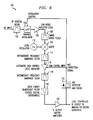
- FIG. 7 shows a portion of an FM HIBOC receiver 170 in which characteristics of a bandreject filter 172 are controlled in accordance with feedback from a post-IF processing stage 174.
- the placement of the filter 172 is the same as that of filter 162 in the FIG. 6 embodiment.
- the filter 172 is an electronically-controllable filter that receives a feedback signal from the post-IF processing stage 174.
- the feedback signal which may be analog or digital, controls the characteristics of the bandreject filter 172 for optimum receiver performance.
- controlled filter characteristics include one or more of rejection bandwidth, rejection band attenuation and center frequency.
- the post-IF processing stage 174 may be, e.g., a demodulation stage or other type of processing stage.
- the invention can improve the performance of digital signal reception, particularly in the presence of multipath reception conditions.
- the invention reduces the need for post-ADC host rejection filtering, thereby simplifying the signal processing performance requirements in the receiver back end.
- FIGS. 3-7 may be implemented using different RF and IF processing elements, in configurations other than those shown.
- a bandreject filter in accordance with the invention may be arranged in locations other than those shown, or in a combination of several locations, e.g., partially in an RF/IF signal path and partially in an AGC path before an AGC detector.
- the invention can be used with a wide variety of other types and arrangements of frequency spectra, e.g., spectra with more than two sidebands, etc., and can be applied to the reception of digital information other than audio, such as video or image information, data, or combinations of these and other types of information.
- the invention may be implemented in numerous applications other than FM HIBOC DAB systems, such as AM HIBOC DAB systems, Internet and satellite broadcasting systems, systems for simultaneous delivery of audio and data, etc.
Landscapes
- Engineering & Computer Science (AREA)
- Signal Processing (AREA)
- Circuits Of Receivers In General (AREA)
- Noise Elimination (AREA)
Abstract
Description
Claims (22)
- A method of processing a received signal in a receiver of a communication system, the received signal including an analog host signal having one or more digital sidebands associated with, the method comprising the step of:
filtering the analog host signal in a bandreject filter arranged at least in part in an intermediate frequency processing stage of the receiver, the bandreject filter substantially attenuating the analog host signal while passing the at least one digital sideband. - The method of claim 1 wherein the bandreject filter is a unitary bandreject filter implemented at a single point in the intermediate frequency processing stage of the receiver.
- The method of claim 1 wherein the bandreject filter is a distributed bandreject filter implemented with multiple sections at a plurality of points, at least one of the plurality of points being in the intermediate frequency stage.
- The method of claim 1 wherein the analog host signal comprises an analog frequency modulated host signal.
- The method of claim 1 wherein first and second digital sidebands are arranged on opposite sides of the analog host signal.
- The method of claim 1 wherein the bandreject filter has a group delay characteristic for a portion of a frequency spectrum associated with the one or more digital sidebands that is selected to equalize at least a portion of a group delay characteristic for a corresponding portion of the frequency spectrum in a signal path of the receiver in which the bandreject filter is arranged.
- The method of claim 1 wherein the bandreject filter is arranged in the intermediate frequency processing stage between an output of an intermediate frequency buffer amplifier and an input of a conversion circuit, with an input of the bandreject filter coupled to a point which is between the output of the intermediate frequency buffer amplifier and the input of the conversion circuit but after a point which drives an input of an automatic gain control circuit, such that an automatic gain control operating point is determined primarily by the analog host signal.
- The method of claim 1 wherein the bandreject filter is arranged in the intermediate frequency processing stage between an output of an intermediate frequency buffer amplifier and an input of an automatic gain control circuit, such that an automatic gain control operating point is determined primarily by the one or more digital sidebands.
- The method of claim 1 wherein the bandreject filter is arranged in the intermediate frequency processing stage between an output of an intermediate frequency bandpass filter and an input of an intermediate frequency buffer amplifier, such that an automatic gain control operating point is determined primarily by the one or more digital sidebands.
- The method of claim 1 wherein at least one filter characteristic of the bandreject filter is adjusted based on feedback from a digital signal processing element in the receiver which processes the information associated with the one or more digital sidebands.
- The method of claim 1 wherein the bandreject filter may be selectively adjusted to permit reception of the analog host signal.
- An apparatus for processing a received signal in a communication system, the received signal including an analog host signal having one or more digital sidebands associated therewith, the apparatus comprising:
a receiver including a bandreject filter arranged at least in part in an intermediate frequency processing stage of the receiver, the bandreject filter substantially attenuating the analog host signal while passing the at least one digital sideband. - The apparatus of claim 12 wherein the bandreject filter is a unitary bandreject filter implemented at a single point in the intermediate frequency processing stage of the receiver.
- The apparatus of claim 12 wherein the bandreject filter is a distributed bandreject filter implemented with multiple sections at a plurality of points, at least one of the plurality of points being in the intermediate frequency stage.
- The apparatus of claim 12 wherein the analog host signal comprises an analog frequency modulated host signal.
- The apparatus of claim 12 wherein first and second digital sidebands are arranged on opposite sides of the analog host signal.
- The apparatus of claim 12 wherein the bandreject filter has a group delay characteristic for a portion of a frequency spectrum associated with the one or more digital sidebands that is selected to equalize at least a portion of a group delay characteristic for a corresponding portion of the frequency spectrum in a signal path of the receiver in which the bandreject filter is arranged.
- The apparatus of claim 12 wherein the bandreject filter is arranged in the intermediate frequency processing stage between an output of an intermediate frequency buffer amplifier and an input of a conversion circuit, with an input of the bandreject filter coupled to a point which is between the output of the intermediate frequency buffer amplifier and the input of the conversion circuit but after a point which drives an input of an automatic gain control circuit, such that an automatic gain control operating point is determined primarily by the analog host signal.
- The apparatus of claim 12 wherein the bandreject filter is arranged in the intermediate frequency processing stage between an output of an intermediate frequency buffer amplifier and an input of an automatic gain control circuit, such that an automatic gain control operating point is determined primarily by the one or more digital sidebands.
- The apparatus of claim 12 wherein the bandreject filter is arranged in the intermediate frequency processing stage between an output of an intermediate frequency bandpass filter and an input of an intermediate frequency buffer amplifier, such that an automatic gain control operating point is determined primarily by the one or more digital sidebands.
- The apparatus of claim 12 wherein at least one filter characteristic of the bandreject filter is adjusted based on feedback from a digital signal processing element in the receiver which processes the information associated with the one or more digital sidebands.
- The apparatus of claim 12 wherein the bandreject filter may be selectively adjusted to permit reception of the analog host signal.
Applications Claiming Priority (2)
| Application Number | Priority Date | Filing Date | Title |
|---|---|---|---|
| US430948 | 1982-09-30 | ||
| US09/430,948 US6577688B1 (en) | 1999-11-01 | 1999-11-01 | Host rejection filtering in a digital audio broadcasting system |
Publications (3)
| Publication Number | Publication Date |
|---|---|
| EP1113604A2 true EP1113604A2 (en) | 2001-07-04 |
| EP1113604A3 EP1113604A3 (en) | 2003-10-29 |
| EP1113604B1 EP1113604B1 (en) | 2017-01-25 |
Family
ID=23709775
Family Applications (1)
| Application Number | Title | Priority Date | Filing Date |
|---|---|---|---|
| EP00309328.3A Expired - Lifetime EP1113604B1 (en) | 1999-11-01 | 2000-10-23 | Filtering method and apparatus for rejecting the host signal in a Digital Audio Broadcasting (DAB) system |
Country Status (4)
| Country | Link |
|---|---|
| US (1) | US6577688B1 (en) |
| EP (1) | EP1113604B1 (en) |
| JP (1) | JP3919440B2 (en) |
| CA (1) | CA2323668C (en) |
Cited By (1)
| Publication number | Priority date | Publication date | Assignee | Title |
|---|---|---|---|---|
| WO2011071468A1 (en) * | 2009-12-09 | 2011-06-16 | Thomson Licensing | Method for protecting satellite reception from strong terrestrial signals |
Families Citing this family (10)
| Publication number | Priority date | Publication date | Assignee | Title |
|---|---|---|---|---|
| NZ508054A (en) * | 2000-11-09 | 2002-11-26 | Tait Electronics Ltd | Double balanced diode mixer for generating an IF output signal from an RF input signal |
| JP3933953B2 (en) * | 2002-02-08 | 2007-06-20 | パイオニア株式会社 | AGC circuit of receiver using a plurality of local oscillation frequencies |
| US7088794B2 (en) * | 2002-02-19 | 2006-08-08 | The United States Of America As Represented By The Secretary Of The Navy | Automatic gain control for digitized RF signal processing |
| JP2003250135A (en) * | 2002-02-22 | 2003-09-05 | Sharp Corp | Tuner |
| JP2005524273A (en) * | 2002-04-26 | 2005-08-11 | トムソン ライセンシング ソシエテ アノニム | Tuner input filter with electronically adjustable center frequency to adapt to antenna characteristics |
| US7221917B2 (en) * | 2002-05-01 | 2007-05-22 | Ibiquity Digital Corporation | Adjacent channel interference mitigation for FM digital audio broadcasting receivers |
| US7623826B2 (en) | 2004-07-22 | 2009-11-24 | Frank Pergal | Wireless repeater with arbitrary programmable selectivity |
| CN101010884A (en) * | 2004-09-08 | 2007-08-01 | 皇家飞利浦电子股份有限公司 | Switch-able band-tracking input filter for combination tuner |
| WO2011062570A1 (en) * | 2009-11-17 | 2011-05-26 | Thomson Licensing | Reuse of a switch ic as a step attenuator |
| JP7215857B2 (en) * | 2018-09-11 | 2023-01-31 | 矢崎総業株式会社 | Amplifier unit and signal transmission system |
Citations (3)
| Publication number | Priority date | Publication date | Assignee | Title |
|---|---|---|---|---|
| US5757854A (en) | 1993-01-12 | 1998-05-26 | Usa Digital Radio Partners, L.P. | In-band on-channel digital broadcasting |
| US5949796A (en) | 1996-06-19 | 1999-09-07 | Kumar; Derek D. | In-band on-channel digital broadcasting method and system |
| US5956624A (en) | 1994-07-12 | 1999-09-21 | Usa Digital Radio Partners Lp | Method and system for simultaneously broadcasting and receiving digital and analog signals |
Family Cites Families (4)
| Publication number | Priority date | Publication date | Assignee | Title |
|---|---|---|---|---|
| EP0820661B1 (en) * | 1996-01-10 | 2004-03-31 | Philips Electronics N.V. | Tv/fm receiver for multimedia applications |
| US5991334A (en) * | 1996-11-12 | 1999-11-23 | Lucent Technologies Inc. | Technique for simultaneous communications of analog frequency-modulated and digitally modulated signals using postcanceling scheme |
| BR9706428A (en) * | 1996-12-19 | 1999-05-25 | Matsushita Electric Industrial Co Ltd | Transmission receiving apparatus |
| US6426780B1 (en) * | 1998-10-14 | 2002-07-30 | Samsung Electronics Co., Ltd. | DTV receiver with low-band final I-F signal filtered for suppressing co-channel interfering NTSC audio carrier |
-
1999
- 1999-11-01 US US09/430,948 patent/US6577688B1/en not_active Expired - Lifetime
-
2000
- 2000-10-17 CA CA002323668A patent/CA2323668C/en not_active Expired - Fee Related
- 2000-10-23 EP EP00309328.3A patent/EP1113604B1/en not_active Expired - Lifetime
- 2000-11-01 JP JP2000334102A patent/JP3919440B2/en not_active Expired - Fee Related
Patent Citations (3)
| Publication number | Priority date | Publication date | Assignee | Title |
|---|---|---|---|---|
| US5757854A (en) | 1993-01-12 | 1998-05-26 | Usa Digital Radio Partners, L.P. | In-band on-channel digital broadcasting |
| US5956624A (en) | 1994-07-12 | 1999-09-21 | Usa Digital Radio Partners Lp | Method and system for simultaneously broadcasting and receiving digital and analog signals |
| US5949796A (en) | 1996-06-19 | 1999-09-07 | Kumar; Derek D. | In-band on-channel digital broadcasting method and system |
Cited By (4)
| Publication number | Priority date | Publication date | Assignee | Title |
|---|---|---|---|---|
| WO2011071468A1 (en) * | 2009-12-09 | 2011-06-16 | Thomson Licensing | Method for protecting satellite reception from strong terrestrial signals |
| CN102668557A (en) * | 2009-12-09 | 2012-09-12 | 汤姆森许可贸易公司 | Method for protecting satellite reception from strong terrestrial signals |
| US8973059B2 (en) | 2009-12-09 | 2015-03-03 | Thomson Licensing | Method for protecting satellite reception from strong terrestrial signals |
| CN102668557B (en) * | 2009-12-09 | 2015-11-25 | 汤姆森许可贸易公司 | A device that protects satellite reception from strong terrestrial signals |
Also Published As
| Publication number | Publication date |
|---|---|
| JP2001189673A (en) | 2001-07-10 |
| CA2323668C (en) | 2004-12-28 |
| US6577688B1 (en) | 2003-06-10 |
| JP3919440B2 (en) | 2007-05-23 |
| EP1113604A3 (en) | 2003-10-29 |
| EP1113604B1 (en) | 2017-01-25 |
| CA2323668A1 (en) | 2001-05-01 |
Similar Documents
| Publication | Publication Date | Title |
|---|---|---|
| US5745846A (en) | Channelized apparatus for equalizing carrier powers of multicarrier signal | |
| CN100446430C (en) | Adjacent Channel Interference Cancellation for FM Digital Audio Broadcasting Receiver | |
| US6178314B1 (en) | Radio receiver with adaptive bandwidth controls at intermediate frequency and audio frequency sections | |
| CN1199364C (en) | radio receiver | |
| US8457574B2 (en) | Front-end integrated circuit for television receivers | |
| EP0766409A2 (en) | Multiband downconverter for digital receivers | |
| EP1290469B1 (en) | Integrated gps/dab receiver | |
| US20040229561A1 (en) | Tuner | |
| JP2001127735A (en) | Power level controller between FAs in RF receiver of CDMA mobile communication base station system | |
| EP1142139B1 (en) | A device and method for reducing the amplitude of signals | |
| US6577688B1 (en) | Host rejection filtering in a digital audio broadcasting system | |
| AU3196399A (en) | Method and apparatus for receiving a plurality of signals having different frequency bandwidths | |
| US20080214137A1 (en) | Receiver For Wireless Communications | |
| US10644734B2 (en) | Low-IF receiver | |
| KR19990023384A (en) | Digital Broadcast Receiver | |
| EP1383248B1 (en) | Superheterodyne receiver | |
| US6813310B1 (en) | Receiver and IC thereof capable of receiving analog broadcast and digital broadcast | |
| CN1147053C (en) | Filtering of receive frequency band | |
| EP1318603B1 (en) | FM receiver with digital bandwidth control | |
| US7343142B2 (en) | Tuner | |
| JP4226806B2 (en) | Signal receiving circuit and signal receiving apparatus | |
| JP3804093B2 (en) | Receiver | |
| JP2002359569A (en) | Broadcast receiver | |
| KR100276258B1 (en) | Digital satellite broadcasting tuner | |
| JPH0330531A (en) | Fm receiver |
Legal Events
| Date | Code | Title | Description |
|---|---|---|---|
| PUAI | Public reference made under article 153(3) epc to a published international application that has entered the european phase |
Free format text: ORIGINAL CODE: 0009012 |
|
| AK | Designated contracting states |
Kind code of ref document: A2 Designated state(s): AT BE CH CY DE DK ES FI FR GB GR IE IT LI LU MC NL PT SE |
|
| AX | Request for extension of the european patent |
Free format text: AL;LT;LV;MK;RO;SI |
|
| PUAL | Search report despatched |
Free format text: ORIGINAL CODE: 0009013 |
|
| AK | Designated contracting states |
Kind code of ref document: A3 Designated state(s): AT BE CH CY DE DK ES FI FR GB GR IE IT LI LU MC NL PT SE |
|
| AX | Request for extension of the european patent |
Extension state: AL LT LV MK RO SI |
|
| 17P | Request for examination filed |
Effective date: 20040419 |
|
| AKX | Designation fees paid |
Designated state(s): DE FR GB |
|
| 17Q | First examination report despatched |
Effective date: 20060726 |
|
| RAP3 | Party data changed (applicant data changed or rights of an application transferred) |
Owner name: LUCENT TECHNOLOGIES INC. |
|
| RAP1 | Party data changed (applicant data changed or rights of an application transferred) |
Owner name: ALCATEL-LUCENT USA INC. |
|
| 111Z | Information provided on other rights and legal means of execution |
Free format text: DE FR GB Effective date: 20130410 |
|
| D11X | Information provided on other rights and legal means of execution (deleted) | ||
| REG | Reference to a national code |
Ref country code: DE Ref legal event code: R079 Ref document number: 60049532 Country of ref document: DE Free format text: PREVIOUS MAIN CLASS: H04H0001000000 Ipc: H04H0040180000 |
|
| RIC1 | Information provided on ipc code assigned before grant |
Ipc: H04H 40/18 20080101AFI20160704BHEP |
|
| GRAP | Despatch of communication of intention to grant a patent |
Free format text: ORIGINAL CODE: EPIDOSNIGR1 |
|
| INTG | Intention to grant announced |
Effective date: 20160824 |
|
| STAA | Information on the status of an ep patent application or granted ep patent |
Free format text: STATUS: GRANT OF PATENT IS INTENDED |
|
| GRAS | Grant fee paid |
Free format text: ORIGINAL CODE: EPIDOSNIGR3 |
|
| GRAA | (expected) grant |
Free format text: ORIGINAL CODE: 0009210 |
|
| STAA | Information on the status of an ep patent application or granted ep patent |
Free format text: STATUS: THE PATENT HAS BEEN GRANTED |
|
| AK | Designated contracting states |
Kind code of ref document: B1 Designated state(s): DE FR GB |
|
| REG | Reference to a national code |
Ref country code: GB Ref legal event code: FG4D |
|
| REG | Reference to a national code |
Ref country code: DE Ref legal event code: R096 Ref document number: 60049532 Country of ref document: DE |
|
| REG | Reference to a national code |
Ref country code: FR Ref legal event code: PLFP Year of fee payment: 18 |
|
| REG | Reference to a national code |
Ref country code: DE Ref legal event code: R097 Ref document number: 60049532 Country of ref document: DE |
|
| PLBE | No opposition filed within time limit |
Free format text: ORIGINAL CODE: 0009261 |
|
| STAA | Information on the status of an ep patent application or granted ep patent |
Free format text: STATUS: NO OPPOSITION FILED WITHIN TIME LIMIT |
|
| 26N | No opposition filed |
Effective date: 20171026 |
|
| REG | Reference to a national code |
Ref country code: FR Ref legal event code: PLFP Year of fee payment: 19 |
|
| PGFP | Annual fee paid to national office [announced via postgrant information from national office to epo] |
Ref country code: FR Payment date: 20180913 Year of fee payment: 19 |
|
| PGFP | Annual fee paid to national office [announced via postgrant information from national office to epo] |
Ref country code: DE Payment date: 20181009 Year of fee payment: 19 |
|
| PGFP | Annual fee paid to national office [announced via postgrant information from national office to epo] |
Ref country code: GB Payment date: 20181017 Year of fee payment: 19 |
|
| REG | Reference to a national code |
Ref country code: DE Ref legal event code: R119 Ref document number: 60049532 Country of ref document: DE |
|
| PG25 | Lapsed in a contracting state [announced via postgrant information from national office to epo] |
Ref country code: DE Free format text: LAPSE BECAUSE OF NON-PAYMENT OF DUE FEES Effective date: 20200501 |
|
| GBPC | Gb: european patent ceased through non-payment of renewal fee |
Effective date: 20191023 |
|
| PG25 | Lapsed in a contracting state [announced via postgrant information from national office to epo] |
Ref country code: FR Free format text: LAPSE BECAUSE OF NON-PAYMENT OF DUE FEES Effective date: 20191031 Ref country code: GB Free format text: LAPSE BECAUSE OF NON-PAYMENT OF DUE FEES Effective date: 20191023 |