EP1113473A2 - Lever switch and detecting device using same - Google Patents
Lever switch and detecting device using same Download PDFInfo
- Publication number
- EP1113473A2 EP1113473A2 EP00128345A EP00128345A EP1113473A2 EP 1113473 A2 EP1113473 A2 EP 1113473A2 EP 00128345 A EP00128345 A EP 00128345A EP 00128345 A EP00128345 A EP 00128345A EP 1113473 A2 EP1113473 A2 EP 1113473A2
- Authority
- EP
- European Patent Office
- Prior art keywords
- contact
- stationary
- lever
- case
- lever switch
- Prior art date
- Legal status (The legal status is an assumption and is not a legal conclusion. Google has not performed a legal analysis and makes no representation as to the accuracy of the status listed.)
- Granted
Links
Images





Classifications
-
- H—ELECTRICITY
- H01—ELECTRIC ELEMENTS
- H01H—ELECTRIC SWITCHES; RELAYS; SELECTORS; EMERGENCY PROTECTIVE DEVICES
- H01H21/00—Switches operated by an operating part in the form of a pivotable member acted upon directly by a solid body, e.g. by a hand
- H01H21/02—Details
- H01H21/18—Movable parts; Contacts mounted thereon
- H01H21/22—Operating parts, e.g. handle
- H01H21/24—Operating parts, e.g. handle biased to return to normal position upon removal of operating force
- H01H21/28—Operating parts, e.g. handle biased to return to normal position upon removal of operating force adapted for actuation at a limit or other predetermined position in the path of a body, the relative movement of switch and body being primarily for a purpose other than the actuation of the switch, e.g. door switch, limit switch, floor-levelling switch of a lift
-
- H—ELECTRICITY
- H01—ELECTRIC ELEMENTS
- H01H—ELECTRIC SWITCHES; RELAYS; SELECTORS; EMERGENCY PROTECTIVE DEVICES
- H01H1/00—Contacts
- H01H1/12—Contacts characterised by the manner in which co-operating contacts engage
- H01H1/36—Contacts characterised by the manner in which co-operating contacts engage by sliding
- H01H1/40—Contact mounted so that its contact-making surface is flush with adjoining insulation
-
- H—ELECTRICITY
- H01—ELECTRIC ELEMENTS
- H01H—ELECTRIC SWITCHES; RELAYS; SELECTORS; EMERGENCY PROTECTIVE DEVICES
- H01H13/00—Switches having rectilinearly-movable operating part or parts adapted for pushing or pulling in one direction only, e.g. push-button switch
- H01H13/02—Details
- H01H13/12—Movable parts; Contacts mounted thereon
- H01H13/14—Operating parts, e.g. push-button
- H01H13/18—Operating parts, e.g. push-button adapted for actuation at a limit or other predetermined position in the path of a body, the relative movement of switch and body being primarily for a purpose other than the actuation of the switch, e.g. door switch, limit switch, floor-levelling switch of a lift
- H01H13/186—Operating parts, e.g. push-button adapted for actuation at a limit or other predetermined position in the path of a body, the relative movement of switch and body being primarily for a purpose other than the actuation of the switch, e.g. door switch, limit switch, floor-levelling switch of a lift wherein the pushbutton is rectilinearly actuated by a lever pivoting on the housing of the switch
-
- H—ELECTRICITY
- H01—ELECTRIC ELEMENTS
- H01H—ELECTRIC SWITCHES; RELAYS; SELECTORS; EMERGENCY PROTECTIVE DEVICES
- H01H19/00—Switches operated by an operating part which is rotatable about a longitudinal axis thereof and which is acted upon directly by a solid body external to the switch, e.g. by a hand
- H01H19/54—Switches operated by an operating part which is rotatable about a longitudinal axis thereof and which is acted upon directly by a solid body external to the switch, e.g. by a hand the operating part having at least five or an unspecified number of operative positions
- H01H19/60—Angularly-movable actuating part carrying no contacts
- H01H19/62—Contacts actuated by radial cams
-
- H—ELECTRICITY
- H01—ELECTRIC ELEMENTS
- H01H—ELECTRIC SWITCHES; RELAYS; SELECTORS; EMERGENCY PROTECTIVE DEVICES
- H01H3/00—Mechanisms for operating contacts
- H01H3/32—Driving mechanisms, i.e. for transmitting driving force to the contacts
- H01H3/46—Driving mechanisms, i.e. for transmitting driving force to the contacts using rod or lever linkage, e.g. toggle
Definitions
- the present invention relates to a lever switch used for various electronic components and also to a detecting device using the lever switch.
- a lever switch used for various electronic components is employed for the purpose of detecting the presence of a recording medium such as a tape and disc or the operation of a mechanism.
- a lever switch used for the purpose of such detection a leaf switch having a combination of a movable contact and a stationary contact which are made up of elastic sheet metal is well known.
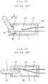
- Fig. 13 is a side sectional view of a conventional lever switch.
- the lever switch comprises a box-type case 1 and a lever 2.
- the case 1 comprises an opening formed in front and an opening 1A formed at the left side.
- the case 1 is made of insulating resin.
- an axle portion 2A In the middle of a lever 2 is formed an axle portion 2A, and the axle portion 2A is rotatably retained in the case 1.
- a driving portion 2B at one end of the lever 2 is located within the case 1, and an operating portion 2C at the other end of the lever is protruded diagonally up to the left from the opening 1A of the case 1.
- Each of a movable contact 3 and a stationary contact 4 which are made up of elastic sheet metal is embedded in an inner right-hand wall 1B opposed to the opening 1A of the case 1.
- the left end of the movable contact 3 elastically comes in contact with the top of the driving portion 2B of the lever 2 to move the operating portion 2C diagonally up to the left.
- a contact portion 4A slightly curved at the left end of the stationary contact 4 opposed to the middle portion of the movable contact 3.
- the front of the case 1 storing the movable contact 3 and stationary contact 4 therein is provided with a cover (not shown).
- the left end portion of the movable contact 3 When the operating portion 2C of the lever 2 is rotated only for a predetermined stroke, the left end portion of the movable contact 3 further moves upward. The middle portion of the movable contact 3 then pushes the contact portion 4A, and due to the pressure, the stationary contact 4 also bends upward. In this way, the movable contact 3 and stationary contact 4 come in contact with each other under a stable pressure.
- the movable contact 3 is moved in the direction of switch height by the lever 2, making the movable contact 3 to come in contact with and apart from the stationary contact 4, and therefore, the switch is required to have a predetermined height equivalent to the movement of the movable contact 3. This makes it difficult to miniaturize the entire switch. Further, since a stable contact pressure is obtained between the stationary contact 4 and movable contact 3 when the stationary contact 4 also bends after movement of the lever 2 only for a predetermined stroke, these contacts are not in stable contact with each other when the lever 2 is halfway in operation.
- a lever switch of the present invention comprises
- the driving portion is located inside the case and is abutting on the curved portion of the movable contact, and when the operating portion is manipulated, the driving portion pushes the curved portion, and then the contact portion comes into contact with or apart from the stationary contact.
- a detecting device of the present invention comprises a casing
- the lever switch has the same configuration as described above. When the moving body is inserted into the casing, the moving body acts upon the operating portion of the lever.
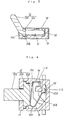
- Fig. 1 is a top sectional view of a lever switch in a first exemplary embodiment of the present invention.
- Fig. 2 is an exploded view of a lever switch in a first exemplary embodiment.
- Fig. 3 is a side sectional view of a lever switch in a first exemplary embodiment.
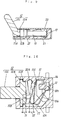
- Fig. 4 is a top sectional view of a lever switch in operation mode in a first exemplary embodiment.
- Fig. 5 is a top sectional view of a lever switch provided with an elastic tongue in a first exemplary embodiment.
- Fig. 6 is a top sectional view of a lever switch provided with an elastic tongue in a first exemplary embodiment.
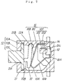
- Fig. 7 is a top sectional view of a lever switch in a second exemplary embodiment of the present invention.
- Fig. 8 is an exploded view of a lever switch in a second exemplary embodiment.
- Fig. 9 is a side sectional view of a lever switch in a second exemplary embodiment.
- Fig. 10 is a top sectional view of a lever switch in operation mode in a second exemplary embodiment.
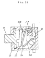
- Fig. 11 is a top sectional view of a lever switch having wire material as a movable contact in a second exemplary embodiment.
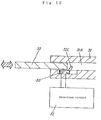
- Fig. 12 is a side sectional view of a lever switch in a third exemplary embodiment.
- Fig. 13 is a side sectional view of a conventional lever switch.
- Fig. 14 is a side sectional view of a conventional lever switch in operation mode.
- a lever switch in accordance with an exemplary embodiment of the present invention comprises
- the case further comprises a box-type shape having a first inner wall opposed to the opening and a second inner wall adjacent to the first inner wall, wherein the stationary contact is disposed on the first inner wall, and the common contact is disposed on the second inner wall.
- the case further comprises a support portion and second inner wall; the support portion is formed at a position spaced apart from the second inner wall as predetermined; the stationary portion includes a small U-shape having a connecting portion and abutment; the connecting portion is connected to the common contact; and a stationary portion having the small U-shape is disposed between the common contact and the support portion.
- the movable contact includes a general U-shape; the movable contact further comprises a first arm portion between the stationary portion and the curved portion and a second arm portion between the contact portion and the curved portion; when the driving portion pushes the curved portion, at least one of the first arm portion and the second arm portion will bend; and due to bending of at least one of the first arm portion and the second arm portion, the contact portion comes into contact with or apart from the stationary contact.
- the lever further comprises an axle portion between the operating portion and the driving portion, and the axle portion is retained in the case and is rotatable in a direction parallel to the stationary contact.
- the movable contact has a shape of thin strip; the contact portion has a semi-circular curvature surface; and the curvature surface is able to make contact with the stationary contact.
- the stationary contact is built into the inner wall of the case so that the surface of the stationary contact is same in height as the inner wall surface of the case, and when the operating portion is manipulated, the contact portion will slide on at least one of the plate-type stationary contact surface and the inner wall surface.
- the lever switch is further provided with a cover; the case further includes a second opening; the case is formed in one piece; and the cover is disposed so as to cover the second opening.
- the case further includes a rotation holding portion, and the lever is rotatably held by the rotation holding portion.
- the movable contact further includes an elastic tongue extending from the stationary portion, and the elastic tongue is abutting on the first arm portion so that the tip of the elastic tongue pushes the first arm portion.
- the movable contact further comprises an elastic tongue of general U-shape that extends from the stationary portion, and the elastic tongue is abutting on the second arm portion so that the tip of the elastic tongue pushes the second arm portion.
- the lever switch further comprises a rotary cam disposed between the lever and the movable contact, wherein one end of the rotary cam is rotatably retained in the case; the surface of the rotary cam comes in contact with the driving portion of the lever; the back of the rotary cam comes in contact with the curved portion of the movable contact; and when the operating portion is manipulated, the driving portion pushes the rotary cam while the rotary cam with its end retained as described pushes the curved portion, and then, the contact portion comes into contact with or apart from the stationary contact.
- a rotary cam disposed between the lever and the movable contact, wherein one end of the rotary cam is rotatably retained in the case; the surface of the rotary cam comes in contact with the driving portion of the lever; the back of the rotary cam comes in contact with the curved portion of the movable contact; and when the operating portion is manipulated, the driving portion pushes the rotary cam while the rotary cam with its end retained as described pushes the curved portion, and then
- the rotary cam has a projection formed thereon, and the projection comes into contact with the driving portion of the lever.
- the movable contact has a wire shape
- the stationary portion has an unwinding coil spring.
- a detecting device in accordance with an exemplary embodiment of the present invention comprises a casing; a lever switch disposed in the casing; a detection circuit electrically connected to the lever switch; and a moving body inserted and detachably disposed in the casing so as to operate the stationary portion of the lever, wherein the lever switch has the same configuration as described above, and when the moving body is inserted into the casing, the moving body acts upon the operating portion of the lever.
- the moving body includes at least one of those selected from a group of a cassette tape, disc and mechanism.
- a lever switch in accordance with an exemplary embodiment of the present invention comprises
- the movable contact pushed by the driving portion of the lever moves in a direction perpendicular to the operating direction of the lever operating portion. Accordingly, the entire switch may be reduced in thickness.
- the stationary portion is press-fitted between the common contact and support portion, and the contact portion of the movable contact being in a state of slightly bending in advance elastically slides on the inner wall of the case or the stationary contact thereby coming in contact with and apart from the stationary contact.
- a constant contact pressure can be maintained at the contacts even when the lever is halfway in operation. As a result, it is possible to obtain a lever switch which assures stable contact at all times.
- Fig. 1 is a top sectional view of a lever switch in the exemplary embodiment 1 of the present invention.
- Fig. 2 is an exploded view of the lever switch, and
- Fig. 3 is a side sectional view of the lever switch.
- the lever switch comprises a case 11, a lever 12, a stationary contact 13, a common contact 14, a movable contact 15, and a cover 16.
- the case 11 is made up of insulating resin.
- the case 11 has a box-type shape, including a second opening formed in front and a first opening 11A formed at the left-hand side.
- the lever 12 has an axle portion 12A.
- the axle portion 12A is formed in the middle of the lever 12.
- the axle portion 12A is rotatably held by the rotation holding portion 11B of the case 11.
- a driving portion 12B at one end of the lever 12 is stored in the case 11 and an operating portion 12C at the other end of same is protruded diagonally up to the left from the first opening 11A.
- the cover 16 is disposed so as to cover the second opening of the case 11.
- the stationary contact 13 is made up of conductive metal.
- the stationary contact has a plate shape.
- the stationary contact 13 is embedded in a right-hand inner wall 11D being a first inner wall opposed to the first opening 11A of the case 11. That is, the stationary contact is embedded in the inner wall in a manner such that the surface of same is exposed.
- the surface of the stationary contact is same in height as the surface of the inner wall 11D and there is no level difference between the stationary contact surface and the inner wall surface.
- the common contact 14 is made up of conductive metal.
- the common contact 14 is embedded in an upper inner wall 11E being a second inner wall.
- the case 11 has a support portion 11C, and the support portion 11C opposed to the common contact 14 is formed in a position spaced apart from the common contact as predetermined.
- the movable contact 15 is made up of elastic sheet metal and has a general U-shape.
- the movable contact 15 is stored in the case 11 in a state of slightly bending.
- the movable contact 15 comprises a curved portion 15A, first arm portion 15B, bend 15C, stationary portion 15F, second arm portion 15G and contact portion 15H.
- the stationary portion 15F includes a connecting portion 15D and abutment 15E.
- the curved portion 15A is located in the middle of the movable contact.
- the curved portion 15A elastically comes in contact with the driving portion 12B of the lever 12.
- the first arm portion 15B extends from one end of the curved portion 15A.
- the stationary portion 15F At the end of the first arm portion 15B is formed the stationary portion 15F via the bend 15C, and the stationary portion 15F has a general U-shape.
- the connecting portion 15D elastically comes in contact with the common contact 14, and the abutment 15E elastically comes in contact with the support portion 11C of the case 11 while the stationary portion 15F being in a state of slightly bending is press-fitted between the common contact 14 and support portion 11C.
- the second arm portion 15G extends from the other end of curved portion 15A of movable contact 15. At the end of the second arm portion 15G is formed the contact portion 15H.
- the contact portion 15H elastically comes in contact with the right-hand inner wall 11D of the case 11.
- the lever 12 supported on axle portion 12A is retained in the case 11 and can be vertically operated in a parallel fashion with the right-hand inner wall of the case 11.
- the lever switch has a configuration as described.
- the movable contact 15 pushed by the driving portion 12B of the lever 12 moves in a direction perpendicular to the operating direction of the operating portion 12C of the lever 12, it is possible to make the entire switch lower in height. That is, the reduction in thickness of the lever switch may be realized.
- the stationary portion 15F of the movable contact 15 is press-fitted between the common contact 14 and the support portion 11C, and the contact portion 15H being in a state of bending in advance elastically slides on the right-hand inner wall 11D of the case 11 or on the stationary contact 13, making the movable contact 15 and stationary contact 13 come into contact with or apart from each other, and thereby, it is possible to keep the contact pressure constant at all times even when the lever 12 is halfway in operation. Accordingly, the lever switch obtained will assure stable contact between the movable contact 15 and the stationary contact 13.
- the contact portion 15H includes a semi-circular curvature surface, and the curvature surface is able to make contact with the stationary contact. This configuration will bring about additional advantages.
- the movable contact 15 has an elastic tongue 15J extending from the stationary portion 15F.
- the elastic tongue 15J is formed in one piece with the stationary portion 15F.
- the end of the elastic tongue 15J is abutted on the inner side of the first arm portion 15B.
- the curved portion 15A of the movable contact 15 pushes the driving portion 12B of the lever 12.
- the force to return the operating portion 12C will be increased. Accordingly, the operating portion 12C of the lever 12 may be precisely returned even when the movable contact 15 is less in width or thickness.
- the movable contact 15 has a generally U-shaped elastic tongue 15K extending from the stationary portion 15F.
- the elastic tongue 15K is formed in one piece with the stationary portion 15F.
- the end of the elastic tongue 15K is abutted on the inner side of the second arm portion 15G.
- the lever switch of the present invention is not limited in terms of configuration, and it is also possible to employ a configuration as follows.
- the contact portion 15H electrically connected to the stationary portion 13 in advance may be electrically disconnected when the operating portion 12C of the lever 12 is rotated to make the movable contact 15 come apart from the stationary contact 13. It is also possible to realize a push-on type switch of this kind.
- first inner wall 11D, second inner wall 11E, support portion 11C, rotation holding portion 11B, first opening 11A and second opening are formed in one body, which form the case 11.
- the present invention is not limited to this configuration, and a configuration formed by combining different members in various ways is also possible, but such configuration will increase the number of parts and the costs.
- the stationary contact is embedded in the inner wall of the case 11.
- such configuration will increase the number of parts and the costs.
- Fig. 7 is a top sectional view of a lever switch in the exemplary embodiment 2 of the present invention
- Fig. 8 is an exploded view of same
- Fig. 9 is a side sectional view of same.
- the lever switch comprises a case 21, a lever 12, a stationary contact 13, a common contact 14, a movable contact 15, and a cover 23.
- the case 21 is made up of insulating resin.
- the case 21 has a box-type shape, including a second opening formed in front and a first opening 21A formed at the left-hand side.
- the lever 12 has an axle portion 12A.
- the axle portion 12A is formed in the middle of the lever 12.
- the axle portion 12A is rotatably held by the rotation holding portion 21B of the case 21.
- a driving portion 12B at one end of the lever 12 is stored in the case 21 and an operating portion 12C at the other end of same is protruded diagonally up to the left from the opening 21A of the case 21.
- the stationary contact 13 is made up of conductive metal.
- the stationary contact 13 is embedded in a right-hand inner wall opposed to the second opening 21A of the case 21.
- the common contact 14 is made up of conductive metal.
- the common contact 14 is embedded in an upper inner wall.
- the case 21 has a support portion 21C, and the support portion 21C opposed to the common contact 14 is formed in a position spaced apart from the common contact as predetermined. The above configuration is identical with that of the exemplary embodiment 1.
- the movable contact 15 is made up of elastic sheet metal and has a general U-shape.
- the movable contact 15 is stored in the case 21 in a state of slightly bending.
- the movable contact 15 comprises a curved portion 15A, first arm portion 15B, bend 15C, stationary portion 15F, second arm portion 15G and contact portion 15H.
- the stationary portion 15F includes a connecting portion 15D and abutment 15E.
- the first arm portion 15B extends from one end of the curved portion 15A. At the end of the first arm portion 15B is formed the stationary portion 15F via the bend 15C, and the stationary portion 15F has a general U-shape.
- the connecting portion 15D elastically comes in contact with the common contact 14, and the abutment 15E elastically comes in contact with the support portion 11C of the case 11 while the stationary portion 15F being in a state of slightly bending is press-fitted between the common contact 14 and the support portion 11C.
- Such configuration is also identical with that of the above exemplary embodiment 1.
- a lever switch in the present exemplary embodiment 2 further includes a rotary cam 22.
- the rotary cam 22 is disposed between the lever 12 and the movable contact 15.
- the rotary cam 22 includes a fulcrum portion 22A, and the fulcrum portion 22A is formed at the top end of the rotary cam 22.
- the fulcrum portion 22A of the rotary cam 22 is rotatably retained in the case 21.
- the driving portion 12B of the lever 12 elastically comes in contact with a projection 22B at the left-hand side of rotary cam 22, and the curved portion 15A of the movable contact 15 elastically comes in contact with the right-hand side of rotary cam 22.
- the contact portion 15H At the end of the second arm portion 15G is formed the contact portion 15H.
- the contact portion 15H elastically comes in contact with the right-hand inner wall of the case 11.
- the cover 23 is disposed so as to cover the front of the case 21.
- the lever 12 supported on axle portion 12A is retained in the case 21 and can be vertically operated in a parallel fashion with the right-hand inner wall of the case 21.
- the lever switch has a configuration as described.
- the curved portion 15A of the movable contact 15 is pushed by the right-hand side of rotary cam 22.
- the movable contact 15 supported on the bend 15C bends and moves to the right in a direction perpendicular to the operating direction of operating portion 12C.
- the contact portion 15H at the end of the second arm portion 15G elastically slides on the right-hand inner wall of the case 21 in the upward direction and then comes into contact with the stationary contact 13. In this way, the stationary contact 13 and common contact 14 will be electrically connected to each other via the movable contact 15.
- the movable contact 15 is precisely operated by the rotary cam 22. Accordingly, it is possible to obtain a switch reduced in thickness and size.
- movable contact 24 includes a wire material
- stationary portion 24A includes an unwinding coil spring.
- first arm portion 24B and second arm portion 24C of the movable contact 24 are short in length, the movable contact will be able to keep a sufficient contact pressure and return force to the stationary contact 13 because of the unwinding coil spring 24A. Accordingly, it is possible to reduce the size of the movable contact 24 and further to obtain a switch reduced in thickness and size.
- wire-type movable contact is also usable for a lever switch in the exemplary embodiment 1 described above, but the advantages obtained will be a little less as compared with the exemplary embodiment 2.
- Fig. 12 is a side sectional view of a detecting device in the exemplary embodiment 3 of the present invention.
- the detecting device comprises a lever switch 30, electronic equipment casing 31, moving body 33 and detection circuit 32.
- the lever switch 30 includes a lever switch as described in the above exemplary embodiments 1 or 2.
- the lever switch 30 is disposed at the bottom of cavity 31A of the casing 31, and the detection circuit 32 is connected to the stationary contact and common contact of the lever switch.
- the moving body 33 includes a recording medium such as a tape and disc or a mechanism or the like such as a cam and shaft.
- a recording medium such as a tape and disc or a mechanism or the like such as a cam and shaft.
- the lever switch 30 is operated when the moving body 33 is inserted into or removed from the cavity 31A of the casing 31.
- the detection circuit 32 detects the electrical connection and disconnection of the lever switch 30. Thus, whether the moving body 33 is in the cavity 31A of casing 31 may be detected. Further, the movement of the moving body 33 and the operation of the mechanism or the like may also be detected.
- a magnetic recording medium such as a cassette tape and disc, optical recording medium and mechanism are employed as a moving body.
- a detecting device in the present exemplary embodiment comprises a lever switch 30 reduced in thickness and capable of assuring stable contact. Due to miniaturization of the lever switch, the purpose of miniaturizing the detecting device will be achieved. That is, it becomes possible to detect the presence of a recording medium and the operation of a mechanism or the like. Further, it is possible to realize a detecting device reduced in thickness and size.
- a miniaturized lever switch As described above, with the configuration of the present invention, it is possible to obtain a miniaturized lever switch. Further, a lever switch which assures electrically stable contact may be obtained. Thus, the purposes of both miniaturization and stabilization may be achieved at the same time. In addition, a detecting device using the lever switch may be reduced in size and thickness. Also, the detecting device is able to reliably detect the operation of the moving body.
Landscapes
- Rotary Switch, Piano Key Switch, And Lever Switch (AREA)
- Tumbler Switches (AREA)
- Switches With Compound Operations (AREA)
- Push-Button Switches (AREA)
Abstract
Description
wherein the movable contact is made of elastic metal,
- the movable contact includes a stationary portion, a contact portion, and a curved portion located between the stationary portion and the contact portion,
- the stationary portion is connected to the common contact, and
- the movable contact is disposed in a state of bending so that the contact portion is able to be in contact or non-contact with the stationary contact.
the driving portion is located inside the case and is abutting on the curved portion of the movable contact, and
when the operating portion is manipulated, the driving portion pushes the curved portion, and then the contact portion comes into contact with or apart from the stationary contact.
- 11, 21
- Case
- 11A, 21A
- Opening, first opening
- 11B, 21B
- Rotation holding portion
- 11C, 21C
- Support portion
- 11D
- First inner wall, right-hand inner wall
- 11E
- Second inner wall, upper inner wall
- 12
- Lever
- 12A
- Axle portion
- 12B
- Driving portion
- 12C
- Operating portion
- 13
- Stationary contact
- 14
- Common contact
- 15, 24
- Movable contact
- 15A
- Curved portion
- 15B, 24B
- First arm portion
- 15C
- Bend
- 15D
- Connecting portion
- 15E
- Abutment
- 15F, 24A
- Stationary portion
- 15G, 24C
- Second arm portion
- 15H
- Contact portion
- 15J, 15K
- Elastic tongue
- 16, 23
- Cover
- 22
- Rotary cam
- 22A
- Fulcrum portion
- 22B
- Projection
- 30
- Lever switch
- 31
- Casing
- 31A
- Cavity
- 32
- Detection circuit
- 33
- Moving body
wherein the movable contact is made of elastic metal, and the movable contact includes a stationary portion, a contact portion, and a curved portion located between the stationary portion and the contact portion, the stationary portion is connected to the common contact, and the movable contact is disposed in a state of bending so that the contact portion is able to come in contact with and apart from the stationary contact, and
wherein the operating portion is protruded from the opening, and the driving portion is located inside the case and is abutting on the curved portion of the movable contact,
wherein when the operating portion is manipulated, the driving portion pushes the curved portion, and then the contact portion comes into contact with or apart from the stationary contact.
wherein the stationary contact is disposed on the first inner wall, and the common contact is disposed on the second inner wall.
wherein one end of the rotary cam is rotatably retained in the case; the surface of the rotary cam comes in contact with the driving portion of the lever; the back of the rotary cam comes in contact with the curved portion of the movable contact; and when the operating portion is manipulated, the driving portion pushes the rotary cam while the rotary cam with its end retained as described pushes the curved portion, and then, the contact portion comes into contact with or apart from the stationary contact.
a casing; a lever switch disposed in the casing; a detection circuit electrically connected to the lever switch; and a moving body inserted and detachably disposed in the casing so as to operate the stationary portion of the lever, wherein the lever switch has the same configuration as described above, and when the moving body is inserted into the casing, the moving body acts upon the operating portion of the lever.
wherein the case has a box-type shape including a first inner wall opposed to the opening and a second inner wall adjacent to the first inner wall, and the support portion is formed at a position spaced apart from the second inner wall as predetermined;
wherein the stationary contact is installed on the first inner wall;
wherein the common contact is installed on the second inner wall;
wherein when the operating portion is manipulated, the driving portion pushes the curved portion, and then the contact portion comes into contact with or apart from the stationary contact.
Claims (22)
- A lever switch, comprising;(a) a case having an opening,(b) a stationary contact disposed in said case,(c) a common contact disposed in said case,(d) a movable contact disposed in said case,in which said movable contact is made of elastic metal, said movable contact includes a stationary portion, a contact portion, and a curved portion located between said stationary portion and said contact portion,said stationary portion is connected to said common contact, andsaid movable contact is disposed in a state of bending so that said contact portion is able to come in contact with or apart from said stationary contact, and(e) a lever having an operating portion and a driving portion,in which said operating portion is protruded from said opening, andsaid driving portion is located in said case and abutting on said curved portion of said movable contact,wherein when said operating portion is manipulated, said driving portion pushes said curved portion, and then said contact portion comes into contact with or apart from said stationary contact.
- The lever switch as defined in claim 1,wherein said case further comprises a box-type shape having a first inner wall opposed to said opening and a second inner wall adjacent to said first inner wall;said stationary contact is disposed on said first inner wall; andsaid common contact is disposed on said second inner wall.
- The lever switch as defined in claim 1,wherein said case further comprises a support portion and a second inner wall;said support portion is formed at a position spaced apart from said second inner wall as predetermined;said stationary portion includes a small U-shape having a connecting portion and abutment; andsaid connecting portion is connected to said common contact, and a stationary portion having said small U-shape is disposed between said common contact and said support portion.
- The lever switch as defined in claim 1,wherein said movable contact includes a general U-shape;said movable contact further comprises a first arm portion between said stationary portion and said curved portion, and a second arm portion between said contact portion and said curved portion;when said driving portion pushes said curved portion, at least one of said first arm portion and said second arm portion will bend; anddue to bending of at least one of said first arm portion and said second arm portion, said contact portion comes into contact with or apart from said stationary contact.
- The lever switch as defined in claim 4,wherein said movable contact further includes an elastic tongue extending from said stationary portion, andsaid elastic tongue is abutting on said first arm portion so that a tip of said elastic tongue pushes said first arm portion.
- The lever switch as defined in claim 4,wherein said movable contact further comprises an elastic tongue of general U-shape that extends from said stationary portion, andsaid elastic tongue is abutting on said second arm portion so that a tip of said elastic tongue pushes said second arm portion.
- The lever switch as defined in claim 1,wherein said lever further comprises an axle portion between said operating portion and said driving portion, andsaid axle portion is rotatably retained in said case in a parallel fashion with said stationary contact.
- The lever switch as defined in claim 1,wherein said movable contact has a shape of thin strip;said contact portion has a semi-circular curvature surface; andsaid curvature surface is able to make contact with said stationary contact.
- The lever switch as defined in claim 1,wherein said stationary contact is built into the inner wall of said case so that a surface of said stationary contact is same in height as the inner wall surface of said case, andwhen said operating portion is manipulated, said contact portion will slide on at least one of the stationary contact surface and the inner wall surface.
- The lever switch as defined in claim 1, further comprising a cover;wherein said case further includes a second opening;said case is formed in one piece; andsaid cover is disposed so as to cover said second opening.
- The lever switch as defined in claim 1,wherein said case further includes a rotation holding portion, andsaid lever is rotatably held by said rotation holding portion.
- The lever switch as defined in claim 1, further comprising a rotary cam disposed between said lever and said movable contact;wherein one end of said rotary cam is rotatably retained in said case;a surface of said rotary cam comes in contact with said driving portion of said lever;a back surface of said rotary cam comes in contact with said curved portion of said movable contact; andwhen said operating portion is manipulated, said driving portion pushes said rotary cam while said rotary cam with its end retained as described pushes said curved portion, and then, said contact portion comes into contact with or apart from said stationary contact.
- The lever switch as defined in claim 12,wherein said rotary cam has a projection formed thereon, andsaid projection comes into contact with said driving portion of said lever.
- The lever switch as defined in claim 1,wherein said movable contact has a wire shape, andsaid stationary portion has an unwinding coil spring.
- A detecting device, comprising:a casing;a lever switch as defined in claim 1 disposed in said casing;a detection circuit electrically connected to said lever switch; anda moving body inserted and detachably disposed in said casing so as to operate said operating portion of said lever,wherein when said moving body is inserted into said casing, said moving body acts upon said operating portion of said lever.
- The detecting device as defined in claim 15, wherein said moving body includes at least one of those selected from a group of a cassette tape, disc and mechanism.
- A lever switch, comprising:(a) a case having an opening and a support portion,in which said case has a box-type shape including a first inner wall opposed to said opening and a second inner wall adjacent to said first inner wall, andsaid support portion is formed at a position spaced apart from said second inner wall as predetermined;(b) a stationary contact disposed within said case,in which said stationary contact is installed on said first inner wall;(c) a common contact disposed within said case,
in which said common contact is installed on said second inner wall;(d) a movable contact disposed in a state of bending within said case,in which said movable contact is made of elastic sheet metal and has a general U-shape,said movable contact includes a stationary portion secured to said case, a contact portion, a curved portion between said stationary portion and said contact portion, a first arm portion between said stationary portion and said curved portion, and a second arm portion between said contact portion and said curved portion,said contact portion is able to come in contact with at least one of said stationary contact and said first inner wall,said stationary portion has a small U-shape and is press-fitted between said common contact and said support portion, andsaid stationary portion comes into contact with said common contact; and(e) a lever having an operating portion, an axle portion and a driving portion,in which said operating portion is protruded from said opening,said axle portion is rotatably retained in said case in a parallel fashion with said stationary contact, andsaid driving portion is located in said case and is abutting on said curved portion of said movable contact;wherein when said operating portion is manipulated, said driving portion pushes said curved portion, and then, said contact portion comes into contact with or apart from said stationary contact. - The lever switch as defined in claim 17,wherein said movable contact further includes an elastic tongue extending from said stationary portion, andsaid elastic tongue is abutting on said first arm portion so that the tip of said elastic tongue pushes said first arm portion.
- The lever switch as defined in claim 17,wherein said movable contact further includes a generally U-shaped elastic tongue extending from said stationary portion, andsaid elastic tongue is abutting on said second arm portion so that a tip of said elastic tongue pushes said second arm portion.
- The lever switch as defined in claim 17, further comprising:a rotary cam disposed between said lever and said movable contact,wherein one end of said rotary cam is rotatably retained in said case;a surface of said rotary cam comes in contact with said driving portion of said lever;a back surface of said rotary cam comes in contact with said curved portion of said movable contact; andwhen said operating portion is manipulated, said driving portion pushes said rotary cam, and said rotary cam supported on said one end pushes said curved portion, and then, said contact portion comes in contact with or apart from said stationary contact.
- The lever switch as defined in claim 17,wherein said movable contact has a wire shape, andsaid stationary portion has an unwinding coil spring.
- A detecting device, comprising:a lever switch as defined in claim 17 which is disposed in said casing;a detection circuit electrically connected to said lever switch; anda moving body inserted and detachably disposed in said casing so as to operate said operating portion of said lever,wherein when said moving body is inserted into said casing, said moving body acts upon said operating portion of said lever.
Applications Claiming Priority (2)
| Application Number | Priority Date | Filing Date | Title |
|---|---|---|---|
| JP36984499 | 1999-12-27 | ||
| JP36984499A JP3893824B2 (en) | 1999-12-27 | 1999-12-27 | Lever switch and detection device using the same |
Publications (3)
| Publication Number | Publication Date |
|---|---|
| EP1113473A2 true EP1113473A2 (en) | 2001-07-04 |
| EP1113473A3 EP1113473A3 (en) | 2003-04-23 |
| EP1113473B1 EP1113473B1 (en) | 2004-11-24 |
Family
ID=18495457
Family Applications (1)
| Application Number | Title | Priority Date | Filing Date |
|---|---|---|---|
| EP00128345A Expired - Lifetime EP1113473B1 (en) | 1999-12-27 | 2000-12-22 | Lever switch and detecting device using same |
Country Status (5)
| Country | Link |
|---|---|
| US (1) | US6525285B2 (en) |
| EP (1) | EP1113473B1 (en) |
| JP (1) | JP3893824B2 (en) |
| CN (1) | CN1258200C (en) |
| MY (1) | MY121501A (en) |
Cited By (3)
| Publication number | Priority date | Publication date | Assignee | Title |
|---|---|---|---|---|
| EP1195787A4 (en) * | 2000-04-14 | 2004-09-15 | Matsushita Electric Industrial Co Ltd | LEVER SWITCH |
| EP1873799A1 (en) * | 2006-06-27 | 2008-01-02 | Omron Corporation | Switch |
| EP3624152A1 (en) * | 2018-09-12 | 2020-03-18 | Mik Electronic Corporation | A brush switch with resistors and manufacturing method thereof |
Families Citing this family (14)
| Publication number | Priority date | Publication date | Assignee | Title |
|---|---|---|---|---|
| DE10237282B4 (en) * | 2001-08-20 | 2022-11-10 | Omron Corp. | Switches, push button switches and rotary lever switches |
| JP3870748B2 (en) * | 2001-10-29 | 2007-01-24 | 松下電器産業株式会社 | Lever switch |
| CN1293584C (en) * | 2003-01-29 | 2007-01-03 | 松下电器产业株式会社 | Lever switch |
| DE60313223D1 (en) * | 2003-02-25 | 2007-05-24 | Smk Kk | SWITCH |
| JP2005116347A (en) | 2003-10-08 | 2005-04-28 | Matsushita Electric Ind Co Ltd | switch |
| JP4333332B2 (en) * | 2003-11-11 | 2009-09-16 | パナソニック株式会社 | switch |
| US6917008B1 (en) * | 2004-01-06 | 2005-07-12 | Zippy Technology Corp. | Microswitch |
| TW200611290A (en) * | 2004-09-24 | 2006-04-01 | Hon Hai Prec Ind Co Ltd | Detector switch |
| JP4687232B2 (en) * | 2005-05-16 | 2011-05-25 | パナソニック株式会社 | switch |
| JP4770652B2 (en) * | 2006-09-12 | 2011-09-14 | パナソニック株式会社 | Lever switch |
| EP2946886B1 (en) | 2014-03-28 | 2017-02-22 | Black & Decker Inc. | Electronic switch and control module for a power tool |
| US10541588B2 (en) | 2017-05-24 | 2020-01-21 | Black & Decker Inc. | Electronic power module for a power tool having an integrated heat sink |
| JP7051604B2 (en) * | 2018-06-15 | 2022-04-11 | 日本電産コパル電子株式会社 | Switch device |
| CN110972424B (en) * | 2019-12-03 | 2025-11-04 | 青岛海尔空调电子有限公司 | Sheet metal connection structure, electrical control box and air conditioner |
Family Cites Families (12)
| Publication number | Priority date | Publication date | Assignee | Title |
|---|---|---|---|---|
| US3591747A (en) | 1969-12-29 | 1971-07-06 | Arrow Hart Inc | Lever operated switch with tiltable contact actuator and flexible contacts |
| JPH02136940U (en) | 1989-04-19 | 1990-11-15 | ||
| US5473130A (en) | 1992-05-19 | 1995-12-05 | Hubbell Incorporated | Three-position receptacle switch assembly |
| JP2570837Y2 (en) | 1992-07-23 | 1998-05-13 | 矢崎総業株式会社 | Lever switch |
| US5369238A (en) * | 1992-08-20 | 1994-11-29 | Alps Electric Co., Ltd. | Spring-return switch |
| FR2699728B1 (en) * | 1992-12-21 | 1995-03-17 | Merlin Gerin | Padlocking device for a manual control lever of a modular electrical device. |
| JPH0855538A (en) * | 1994-08-11 | 1996-02-27 | T K R:Kk | Detecting switch |
| JP3248392B2 (en) * | 1995-06-06 | 2002-01-21 | 松下電器産業株式会社 | Lever switch |
| JP3648835B2 (en) * | 1996-04-19 | 2005-05-18 | 松下電器産業株式会社 | Lever switch |
| JPH1021788A (en) * | 1996-07-01 | 1998-01-23 | Matsushita Electric Ind Co Ltd | Lever switch |
| US6262961B1 (en) * | 1997-11-18 | 2001-07-17 | Matsushita Electric Industrial Co., Ltd. | Disk loading device and disk cartridge |
| JP3843583B2 (en) * | 1998-03-12 | 2006-11-08 | 松下電器産業株式会社 | Lever switch and its operation method |
-
1999
- 1999-12-27 JP JP36984499A patent/JP3893824B2/en not_active Expired - Fee Related
-
2000
- 2000-12-22 EP EP00128345A patent/EP1113473B1/en not_active Expired - Lifetime
- 2000-12-26 MY MYPI20006204A patent/MY121501A/en unknown
- 2000-12-27 CN CNB001377531A patent/CN1258200C/en not_active Expired - Lifetime
- 2000-12-27 US US09/748,877 patent/US6525285B2/en not_active Expired - Fee Related
Cited By (4)
| Publication number | Priority date | Publication date | Assignee | Title |
|---|---|---|---|---|
| EP1195787A4 (en) * | 2000-04-14 | 2004-09-15 | Matsushita Electric Industrial Co Ltd | LEVER SWITCH |
| EP1873799A1 (en) * | 2006-06-27 | 2008-01-02 | Omron Corporation | Switch |
| EP3624152A1 (en) * | 2018-09-12 | 2020-03-18 | Mik Electronic Corporation | A brush switch with resistors and manufacturing method thereof |
| KR20200030439A (en) * | 2018-09-12 | 2020-03-20 | 미크덴시고교가부시키가이샤 | The brush switch with the resistor and manufacturing method thereof |
Also Published As
| Publication number | Publication date |
|---|---|
| MY121501A (en) | 2006-01-28 |
| CN1302073A (en) | 2001-07-04 |
| US6525285B2 (en) | 2003-02-25 |
| JP3893824B2 (en) | 2007-03-14 |
| EP1113473A3 (en) | 2003-04-23 |
| EP1113473B1 (en) | 2004-11-24 |
| CN1258200C (en) | 2006-05-31 |
| US20010025780A1 (en) | 2001-10-04 |
| JP2001184994A (en) | 2001-07-06 |
Similar Documents
| Publication | Publication Date | Title |
|---|---|---|
| EP1113473B1 (en) | Lever switch and detecting device using same | |
| EP1760841B1 (en) | Memory card socket structure | |
| JP3991577B2 (en) | Lever switch | |
| US20040263293A1 (en) | Electromagnetic relay | |
| US6633013B2 (en) | Lever switch | |
| WO2001080264A1 (en) | Lever switch | |
| JP3923732B2 (en) | Switch device | |
| JP3854789B2 (en) | Switch device | |
| US5924556A (en) | Push switch device | |
| TW477995B (en) | Switch device | |
| EP1498922A1 (en) | Switch assembly | |
| JP2000149715A (en) | switch | |
| JP2010250944A (en) | Lever switch | |
| JP4030730B2 (en) | Switch device | |
| KR100551920B1 (en) | Slide type electric component | |
| JP2005332688A (en) | Switching arrangement | |
| JP2002151205A (en) | Card connector device | |
| JPH113633A (en) | Lever switch | |
| JP2004014456A (en) | Connector device for cards | |
| JP3964093B2 (en) | Switch device | |
| JP2007305458A (en) | Switch | |
| JPS6364806B2 (en) | ||
| JP3157249U (en) | switch | |
| JP2002313192A (en) | Rotative operation type electric parts | |
| JP2003178842A (en) | Connector device |
Legal Events
| Date | Code | Title | Description |
|---|---|---|---|
| PUAI | Public reference made under article 153(3) epc to a published international application that has entered the european phase |
Free format text: ORIGINAL CODE: 0009012 |
|
| AK | Designated contracting states |
Kind code of ref document: A2 Designated state(s): AT BE CH CY DE DK ES FI FR GB GR IE IT LI LU MC NL PT SE TR |
|
| AX | Request for extension of the european patent |
Free format text: AL;LT;LV;MK;RO;SI |
|
| PUAL | Search report despatched |
Free format text: ORIGINAL CODE: 0009013 |
|
| AK | Designated contracting states |
Designated state(s): AT BE CH CY DE DK ES FI FR GB GR IE IT LI LU MC NL PT SE TR |
|
| AX | Request for extension of the european patent |
Extension state: AL LT LV MK RO SI |
|
| 17P | Request for examination filed |
Effective date: 20030704 |
|
| 17Q | First examination report despatched |
Effective date: 20031013 |
|
| AKX | Designation fees paid |
Designated state(s): FI SE |
|
| REG | Reference to a national code |
Ref country code: DE Ref legal event code: 8566 |
|
| GRAP | Despatch of communication of intention to grant a patent |
Free format text: ORIGINAL CODE: EPIDOSNIGR1 |
|
| GRAS | Grant fee paid |
Free format text: ORIGINAL CODE: EPIDOSNIGR3 |
|
| GRAA | (expected) grant |
Free format text: ORIGINAL CODE: 0009210 |
|
| AK | Designated contracting states |
Kind code of ref document: B1 Designated state(s): FI SE |
|
| REG | Reference to a national code |
Ref country code: IE Ref legal event code: FG4D |
|
| REG | Reference to a national code |
Ref country code: SE Ref legal event code: TRGR |
|
| PLBE | No opposition filed within time limit |
Free format text: ORIGINAL CODE: 0009261 |
|
| STAA | Information on the status of an ep patent application or granted ep patent |
Free format text: STATUS: NO OPPOSITION FILED WITHIN TIME LIMIT |
|
| 26N | No opposition filed |
Effective date: 20050825 |
|
| PGFP | Annual fee paid to national office [announced via postgrant information from national office to epo] |
Ref country code: SE Payment date: 20061206 Year of fee payment: 7 |
|
| EUG | Se: european patent has lapsed | ||
| PG25 | Lapsed in a contracting state [announced via postgrant information from national office to epo] |
Ref country code: SE Free format text: LAPSE BECAUSE OF NON-PAYMENT OF DUE FEES Effective date: 20071223 |
|
| PGFP | Annual fee paid to national office [announced via postgrant information from national office to epo] |
Ref country code: FI Payment date: 20121211 Year of fee payment: 13 |
|
| PG25 | Lapsed in a contracting state [announced via postgrant information from national office to epo] |
Ref country code: FI Free format text: LAPSE BECAUSE OF NON-PAYMENT OF DUE FEES Effective date: 20131222 |