FIELD OF THE INVENTION
This invention relates to photographic materials. In a preferred
form it relates to base materials for photographic reflective display.
BACKGROUND OF THE INVENTION
It is known in the art that photographic display materials are
utilized for advertising, as well as decorative displays of photographic images.
Since these display materials are used in advertising, the image quality of the
display material is critical in expressing the quality message of the product or
service being advertised. Further, a photographic display image needs to be high
impact, as it attempts to draw consumer attention to the display material and the
desired message being conveyed. Typical applications for display material
include product and service advertising in public places such as airports, buses and
sports stadiums, movie posters, and fine art photography. The desired attributes of
a quality, high impact photographic display material are a slight blue density
minimum, durability, sharpness, and flatness. Cost is also important, as display
materials tend to be expensive compared with alternative display material
technology, mainly lithographic images on paper. For display materials,
traditional color paper is undesirable, as it suffers from a lack of durability for the
handling, photoprocessing, and display of large format images.
In the formation of color paper it is known that the base paper has
applied thereto a layer of polymer, typically polyethylene. This layer serves to
provide waterproofing to the paper, as well as providing a smooth surface on
which the photosensitive layers are formed. The formation of a suitably smooth
surface is difficult, requiring great care and expense to ensure proper laydown and
cooling of the polyethylene layers. The formation of a suitably smooth surface
would also improve image quality, as the display material would have more
apparent blackness, as the reflective properties of the improved base are more
specular than the prior materials. As the whites are whiter and the blacks are
blacker, there is more range in between and, therefore, contrast is enhanced. It
would be desirable if a more reliable and improved surface could be formed at less
expense.
Prior art photographic reflective papers comprise a melt extruded
polyethylene layer which also serves as a carrier layer for optical brightener and
other whitener materials as well as tint materials. It would be desirable if the
optical brightener, whitener materials and tints, rather than being dispersed
throughout the single layer of polyethylene could be concentrated nearer the
surface of the layer where they would be more effective optically.
Prior art photographic reflective display materials have light
sensitive silver halide emulsions coated directly onto a gelatin coated opacified
polyester base sheet. Since the emulsion does not contain any materials to opacify
the imaging element, white pigments such as BaSO4 have been added to the
polyester base sheet to provide an imaging element with both opacity and the
desired reflection properties. Also, optical brighteners are added to the polyester
base sheet to give the sheet a blue tint in the presence of an ultraviolet light
source. The addition of the white pigments into the polyester sheet causes several
manufacturing problems which can either reduce manufacturing efficiency or
reduce image quality. The addition of white pigment to the polyester base causes
manufacturing problems, such as die lines and pigment agglomeration, which
reduce the efficiency at which photographic display material can be manufactured.
It would be desirable if the optical brightener, whitener materials and tints, rather
than being dispersed throughout the polyester base sheet, could be concentrated
nearer the surface where they would be more effective optically and improve
manufacturing efficiency.
Prior art reflective photographic materials with a polyester base use
a TiO2 pigmented polyester base onto which light sensitive silver halide emulsions
are coated. It has been proposed in WO 94/04961 to use opaque polyester
containing 10% to 25% TiO2 for a photographic support. The TiO2 in the
polyester gives the reflective display materials an undesirable opalescence
appearance. The TiO2 pigmented polyester also is expensive because the TiO2
must be dispersed into the entire thickness, typically from 100 to 180
micrometers. This also gives the polyester support a slight yellow tint which is
undesirable for a photographic display material. For use as a photographic display
material, the polyester support containing TiO2 must be tinted blue to offset the
yellow tint of the polyester causing a loss in desirable whiteness and adding cost
to the display material. It would be desirable if a reflective display support did not
contain any TiO2 in the base and TiO2 could be concentrated near the light
sensitive emulsion.
Prior art photographic display material uses polyester as a base for
the support. Typically the polyester support is from 150 to 250 micrometers thick
to provide the required stiffness. A thinner base material would be lower in cost
and allow for roll-handling efficiency, as the rolls would weigh less and be smaller
in diameter. It would be desirable to use a base material that had the required
stiffness but was thinner to reduce cost and improve roll-handling efficiency.
PROBLEM TO BE SOLVED BY THE INVENTION
There is a continuing need for tough scratch resistant display
materials that are low in cost and provide superior whiteness and color saturation.
SUMMARY OF THE INVENTION
It is an object of the invention to overcome disadvantages of prior
reflective display materials.
It is another object to provide lower cost, high quality reflective
display materials.
These and other objects of the invention are accomplished by a
photographic element comprising at least one photosensitive layer, and a base
material comprising an upper and lower biaxially oriented polymer sheet separated
by a paper sheet, wherein said base material has a thickness of greater than 254
micrometers, a stiffness of greater than 325 millinewtons in any direction, and an
upper surface roughness of less than 0.45 micrometers at a spatial frequency of
between 0.30 and 6.35 millimeters, and a transmission percent of less than 15
percent.
ADVANTAGEOUS EFFECT OF THE INVENTION
The invention provides improved reflective display materials that
provide whiter whites and have higher durability compared with polymer
materials. The reflective display materials further provide a wider contrast range
and sharper images. The invention materials are lower in cost compared to
polymer materials.
BRIEF DESCRIPTION OF THE DRAWING
The Figure illustrates the D LogH characteristic curve of a
photographic element of the invention.
DETAILED DESCRIPTION OF THE INVENTION
The invention has numerous advantages over prior practices in the
art. The invention provides a display material that is scratch resistant and low is
cost, as the material is overlaminated in its preferred form. The material provides
superior color reproduction, superior whiteness, and sharpness. The material is
readily digital processible for image formation. The material provides superior
maximum density without having significant fringing of edges and text. The
product has superior color gamut and is able to reproduce a broader range of color.
Furthermore, when the base element of this invention is combined with a superior
digitally compatible emulsion, a synergistic benefit is obtained as the whites are
whiter and the blacks are blacker, and both pictorial scenes and text can now be
combined with extremely sharp edges without text fringing and rastering, as the
base is very reflective. The laminated base material utilized in the invention has
superior stiffness which enables a thinner overlaminate, thereby resulting in cost
savings as well as reduced weight of the product for equivalent stiffness as
compared with previous products.
The reflective display material of the invention has a whiter white
than prior materials. Prior materials were somewhat yellow and had a higher
minimum density, as there was a large quantity of white pigment in the polymer
base sheet. Typically when a large quantity of white TiO2 is loaded into a paper
base, it becomes somewhat yellowish rather than being the desired neutral
reflective white. The display material of the invention provides sharper images, as
they have higher accutance due to the efficient reflective layer on the upper
surface of the biaxially oriented polyolefin sheet. There is a visual contrast
improvement in the display material of the invention, as the lower density is lower
than prior product and the upper amount of density has been visually increased.
The display material has a more maximum black, as the reflective properties of the
improved base are more specular than the prior materials. As the whites are
whiter and the blacks are blacker, there is more range in between and, therefore,
contrast is enhanced. These and other advantages will be apparent from the
detailed description below.
The terms as used herein, "top", "upper", "emulsion side", and
"face" mean the side or toward the side of the photographic member bearing the
imaging layers. The terms "bottom", "lower side", and "back" mean the side or
toward the side of the photographic member opposite from the side bearing the
photosensitive imaging layers or developed image.
A preferred embodiment of this invention utilizes a paper sheet that
has a basis weight of greater than 200 g/m2. Such a basis weight is highly
desirable because it allows the more expensive overlaminate to be down gauged
(thinner), resulting in significant cost savings. Furthermore, the heavier basis
weight of the paper sheet provides a feel of high quality. A paper sheet with a
thickness of between 170 and 230 µm is the most desired. When these materials
are used for signage in a display booth, its superior weight, thickness, and stiffness
minimizes sag. In the preferred embodiment a photographic element of thickness
between 325 and 650 millinewtons is desired, as the materials are stiffer providing
a display material. The photographic element with the overlaminate becomes self-supporting.
High performing biaxially oriented polyolefin sheet may be utilized
for the sheet on the topside of the laminated base of the invention. Microvoided
composite biaxially oriented sheets are a preferred embodiment because the voids
provide opacity without the use of TiO2. Microvoided composite oriented sheets are
conveniently manufactured by coextrusion of the core and surface layers, followed
by biaxial orientation, whereby voids are formed around void-initiating material
contained in the core layer. Such composite sheets are disclosed in, for example,
U.S. Patent Nos. 4,377,616; 4,758,462 and 4,632,869.
The core of the preferred topside composite sheet should be from 15 to
95% of the total thickness of the sheet, preferably from 30 to 85% of the total
thickness. The nonvoided skin(s) should thus be from 5 to 85% of the sheet,
preferably from 15 to 70% of the thickness.
The density (specific gravity) of the topside composite sheet, expressed
in terms of "percent of solid density" is calculated as follows:
Composite Sheet DensityPolymer Density x 100 = % of Solid Density
should be between 45% and 100%, preferably between 67% and 100%. As the
percent solid density becomes less than 67%, the topside composite sheet becomes
less manufacturable due to a drop in tensile strength and it becomes more susceptible
to physical damage.
The total thickness of the topside composite sheet can range from 12 to
100 micrometers, preferably from 20 to 70 micrometers. Below 20 micrometers, the
microvoided sheets may not be thick enough to minimize any inherent non-planarity
in the support and would be more difficult to manufacture. At thickness higher than
70 micrometers, little improvement in either surface smoothness or mechanical
properties are seen, and so there is little justification for the further increase in cost for
extra materials.
"Void" is used herein to mean devoid of added solid and liquid
matter, although it is likely the "voids" contain gas. The void-initiating particles
which remain in the finished packaging sheet core should be from 0.1 to 10
micrometers in diameter, preferably round in shape, to produce voids of the
desired shape and size. The size of the void is also dependent on the degree of
orientation in the machine and transverse directions. Ideally, the void would
assume a shape that is defined by two opposed and edge contacting concave disks.
In other words, the voids tend to have a lens-like or biconvex shape. The voids
are oriented so that the two major dimensions are aligned with the machine and
transverse directions of the sheet. The Z-direction axis is a minor dimension and
is roughly the size of the cross diameter of the voiding particle. The voids
generally tend to be closed cells, and thus there is virtually no path open from one
side of the voided-core to the other side through which gas or liquid can traverse.
The void-initiating material may be selected from a variety of
materials, and should be present in an amount of about 5-50% by weight based on
the weight of the core matrix polymer. Preferably, the void-initiating material
comprises a polymeric material. When a polymeric material is used, it may be a
polymer that can be melt-mixed with the polymer from which the core matrix is
made and be able to form dispersed spherical particles as the suspension is cooled
down. Examples of this would include nylon dispersed in polypropylene,
polybutylene terephthalate in polypropylene, or polypropylene dispersed in
polyethylene terephthalate. If the polymer is preshaped and blended into the
matrix polymer, the important characteristic is the size and shape of the particles.
Spheres are preferred and they can be hollow or solid. These spheres may be
made from cross-linked polymers which are members selected from the group
consisting of an alkenyl aromatic compound having the general formula Ar-C(R)=CH2,
wherein Ar represents an aromatic hydrocarbon radical, or an
aromatic halohydrocarbon radical of the benzene series and R is hydrogen or the
methyl radical; acrylate-type monomers include monomers of the formula
CH2=C(R')-C(O)(OR) wherein R is selected from the group consisting of
hydrogen and an alkyl radical containing from about 1 to 12 carbon atoms and R'
is selected from the group consisting of hydrogen and methyl; copolymers of vinyl
chloride and vinylidene chloride, acrylonitrile and vinyl chloride, vinyl bromide,
vinyl esters having formula CH2=CH(O)COR, wherein R is an alkyl radical
containing from 2 to 18 carbon atoms; acrylic acid, methacrylic acid, itaconic
acid, citraconic acid, maleic acid, fumaric acid, oleic acid, vinylbenzoic acid; the
synthetic polyester resins which are prepared by reacting terephthalic acid and
dialkyl terephthalics or ester-forming derivatives thereof, with a glycol of the
series HO(CH2)nOH wherein n is a whole number within the range of 2-10 and
having reactive olefinic linkages within the polymer molecule, the above
described polyesters which include copolymerized therein up to 20 percent by
weight of a second acid or ester thereof having reactive olefinic unsaturation and
mixtures thereof, and a cross-linking agent selected from the group consisting of
divinylbenzene, diethylene glycol dimethacrylate, diallyl fumarate, diallyl
phthalate and mixtures thereof.
Examples of typical monomers for making the crosslinked polymer
include styrene, butyl acrylate, acrylamide, acrylonitrile, methyl methacrylate,
ethylene glycol dimethacrylate, vinyl pyridine, vinyl acetate, methyl acrylate,
vinylbenzyl chloride, vinylidene chloride, acrylic acid, divinylbenzene,
acrylamidomethylpropane sulfonic acid, vinyl toluene, etc. Preferably, the cross-linked
polymer is polystyrene or poly(methyl methacrylate). Most preferably, it is
polystyrene and the cross-linking agent is divinylbenzene.
Processes well known in the art yield non-uniformly sized
particles, characterized by broad particle size distributions. The resulting beads
can be classified by screening the beads spanning the range of the original
distribution of sizes. Other processes such as suspension polymerization, limited
coalescence, directly yield very uniformly sized particles.
The void-initiating materials may be coated with agents to facilitate
voiding. Suitable agents or lubricants include colloidal silica, colloidal alumina,
and metal oxides such as tin oxide and aluminum oxide. The preferred agents are
colloidal silica and alumina, most preferably, silica. The cross-linked polymer
having a coating of an agent may be prepared by procedures well known in the art.
For example, conventional suspension polymerization processes wherein the agent
is added to the suspension is preferred. As the agent, colloidal silica is preferred.
The void-initiating particles can also be inorganic spheres,
including solid or hollow glass spheres, metal or ceramic beads or inorganic
particles such as clay, talc, barium sulfate, and calcium carbonate. The important
thing is that the material does not chemically react with the core matrix polymer to
cause one or more of the following problems: (a) alteration of the crystallization
kinetics of the matrix polymer, making it difficult to orient, (b) destruction of the
core matrix polymer, (c) destruction of the void-initiating particles, (d) adhesion
of the void-initiating particles to the matrix polymer, or (e) generation of
undesirable reaction products, such as toxic or high color moieties. The void-initiating
material should not be photographically active or degrade the
performance of the photographic element in which the biaxially oriented
polyolefin film is utilized.
For the top biaxially oriented sheets on the polymer base toward
the emulsion, suitable classes of thermoplastic polymers for the biaxially oriented
sheet and the core matrix-polymer of the preferred composite sheet comprise
polyolefins. Suitable polyolefins include polypropylene, polyethylene,
polymethylpentene, polystyrene, polybutylene and mixtures thereof. Polyolefin
copolymers, including copolymers of propylene and ethylene such as hexene,
butene, and octene are also useful. Polypropylene is preferred, as it is low in cost
and has desirable strength properties. The biaxially oriented sheets used in the
invention contain an integral emulsion bonding layer which avoids the need for
expensive priming coatings or energy treatments. The bonding layer used in the
invention is a low density polyethylene skin on the biaxially oriented sheet.
Gelatin based silver halide emulsion layers of the invention have been shown to
adhere well to low density polyethylene. The integral bonding skin layer also
serves as a carrier for the blue tints that correct for the native yellowness of the
gelatin based silver halide image element. Concentrating the blue tints in the thin,
skin layer reduces the amount of expensive blue tint materials when compared to
prior art photographic papers that contain blue tint materials dispersed in a single
thick layer of polyethylene.
The nonvoided skin layers of the top and bottom composite sheet
can be made of the same polymeric materials as listed above for the core matrix.
The composite sheet can be made with skin(s) of the same polymeric material as
the core matrix, or it can be made with skin(s) of different polymeric composition
than the core matrix. For compatibility, an auxiliary layer can be used to promote
adhesion of the skin layer to the core.
The total thickness of the top most skin layer or exposed surface
layer below the image layers should be between 0.20 µm and 1.5 µm, preferably
between 0.5 and 1.0 µm. Below 0.5 µm any inherent non-planarity in the
coextruded skin layer may result in unacceptable color variation. At skin
thickness greater than 1.0 µm, there is a reduction in the photographic optical
properties such as image resolution. At thickness greater that 1.0 µm there is also
a greater material volume to filter for contamination such as clumps, poor color
pigment dispersion, or contamination.
Addenda may be added to the topmost skin layer to change the
color of the imaging element. For photographic use, a white base with a slight
bluish tinge is preferred. The addition of the slight bluish tinge may be
accomplished by any process which is known in the art including the machine
blending of color concentrate prior to extrusion and the melt extrusion of blue
colorants that have been pre-blended at the desired blend ratio. Colored pigments
that can resist extrusion temperatures greater than 320°C are preferred, as
temperatures greater than 320°C are necessary for coextrusion of the skin layer.
Blue colorants used in this invention may be any colorant that does not have an
adverse impact on the imaging element. Preferred blue colorants include
Phthalocyanine blue pigments, Cromophtal blue pigments, Irgazin blue pigments,
Irgalite organic blue pigments, and pigment Blue 60.
One detail of this invention is that a very thin coating (0.2 to 1.5
µm) on the surface immediately below the emulsion layer can be made by
coextrusion and subsequent stretching in the width and length direction. It has
been found that this layer is, by nature, extremely accurate in thickness and can be
used to provide all the color corrections, which are usually distributed throughout
the thickness of the sheet between the emulsion and the polymer base. This
topmost layer is so efficient that the total colorants needed to provide a correction
are less than one-half the amount needed if the colorants are dispersed throughout
thickness. Colorants are often the cause of spot defects due to clumps and poor
dispersions. Spot defects, which decrease the commercial value of images, are
improved with this invention because less colorant is used and high quality
filtration to clean up the colored layer is much more feasible since the total
volume of polymer with colorant is only typically 2 to 10 percent of the total
polymer between the base polymer and the photosensitive layer.
The addition of TiO2 or other white pigment known in the art to a
layer of the photographic element of this invention contributes to the optical
performance of the top sheet. In a preferred embodiment of this invention, the
TiO2 is placed in a skin layer of the top biaxially oriented polymer sheet between
the voided layer and the light sensitive silver halide emulsion. The TiO2 is
preferred because it adds to the sharpness of the image as well as contributes to the
overall opacity and whiteness of the photographic element. Additional white
pigment may be added to the tie layer that is used to adhere the biaxially oriented
polymer sheet to the base substrate. In this case the pigments contributes to
improved opacity and sharpness.
Addenda may be added to the biaxially oriented sheet of this
invention so that when the biaxially oriented sheet is viewed from a surface, the
imaging element emits light in the visible spectrum when exposed to ultraviolet
radiation. Emission of light in the visible spectrum allows for the support to have
a desired background color in the presence of ultraviolet energy. This is
particularly useful when images are viewed under lighting that contains ultraviolet
energy and may be used to optimize image quality for consumer and commercial
applications. The selection of white pigment in the biaxially oriented polymer
sheet is important when there is ultraviolet illumination of the photographic
image. In some cases the anatase form of TiO2 is preferred because it absorbs less
ultraviolet energy and provides greater illumination in the blue region. The use of
BaSO4 as the primary white pigment is preferred because it has very low
ultraviolet absorbency and therefore has enhanced visible blue light reflection,
which make the display materials appear very white. In the case when superior
sharpness is desired the rutile form of TiO2 is preferred.
Addenda known in the art to emit visible light in the blue spectrum
are preferred. Consumers generally prefer a slight blue tint to white defined as a
negative b* compared to a white defined as a b* within one b* unit of zero. b* is
the measure of yellow/blue in CIE space. A positive b* indicates yellow while a
negative b* indicates blue. The addition of addenda that emits in the blue
spectrum allows for tinting the support without the addition of colorants, which
would decrease the whiteness of the image. The preferred emission is between 1
and 5 delta b* units. Delta b* is defined as the b* difference measured when a
sample is illuminated ultraviolet light source and a light source without any
significant ultraviolet energy. Delta b* is the preferred measure to determine the
net effect of adding an optical brightener to the top biaxially oriented sheet of this
invention. Emissions less than 1 b* unit can riot be noticed by most customers
therefore is it not cost effective to add optical brightner to the biaxially oriented
sheet. An emission greater that 5 b* units would interfere with the color balance
of the prints making the whites appear too blue for most consumers.
A preferred addendum of this invention is an optical brightener.
An optical brightener is colorless, fluorescent, organic compound that absorbs
ultraviolet light and emits it as visible blue light. Examples include but are not
limited to derivatives of 4,4'-diaminostilbene-2,2'-disulfonic acid, coumarin
derivatives such as 4-methyl-7-diethylaminocoumarin, 1-4-Bis (O-Cyanostyryl)
Benzol and 2-Amino-4-Methyl Phenol.
The optical brightener may be added to any layer in the multilayer
coextruded biaxially oriented polyolefin sheet. The preferred locations are
adjacent to or in the top most surface layer of the biaxially oriented sheet. This
allows for the efficient concentration of optical brightener which results in less
optical brightener being used when compared to traditional photographic supports.
When the desired weight % loading of the optical brightener begins to approach
the concentration at which the optical brightener migrates to the surface of the
support forming crystals in the imaging layer, the addition of optical brightener
into the layer adjacent to the exposed layer is preferred. When optical brightener
migration is a concern as with light sensitive silver halide imaging systems, the
preferred exposed layer comprised polyethylene. In this case, the migration from
the layer adjacent to the exposed layer is significantly reduced allowing for much
higher optical brightener levels to be used to optimize image quality. Locating the
optical brightener in the layer adjacent to the exposed layer allows for a less
expensive optical brightener to be used as the exposed layer, which is substantially
free of optical brightner, prevents significant migration of the optical brightener.
Another preferred method to reduce unwanted optical brightner migration is to use
polypropylene for the layer adjacent to the exposed surface. Since optical
brightener is more soluble in polypropylene than polyethylene, the optical
brightener is less likely to migrate from polypropylene.
A biaxially oriented sheet of this invention, which has a
microvoided core, is preferred. The microvoided core adds opacity and whiteness
to the imaging support further improving imaging quality. Combining the image
quality advantages of a microvoided core with a material which absorbs ultraviolet
energy and emits light in the visible spectrum allows for the unique optimization
of image quality as the image support can have a tint when exposed to ultraviolet
energy yet retain excellent whiteness when the image is viewed using lighting that
does not contain high amounts of ultraviolet energy such as some types of indoor
lighting. The preferred number of voids in the vertical direction at substantially
every point is greater than six. The number of voids in the vertical direction is the
number of polymer / gas interfaces present in the voided layer. The voided layer
functions as an opaque layer because of the index of refraction changes between
polymer / gas interfaces. Greater than six voids is preferred because at 4 voids or
less, little improvement in the opacity of the film is observed and thus does not
justify the added expense to void the biaxially oriented sheet of this invention.
The biaxially oriented top sheet may also contain pigments, which
are known to improve the photographic responses such as whiteness or sharpness.
Titanium dioxide is used in this invention to improve image sharpness. The TiO2
used may be either anatase or rutile type. In the case of optical properties, rutile is
the preferred because of the unique particle size and geometry. Further, both
anatase and rutile TiO2 may be blended to improve both whiteness and sharpness.
Examples of TiO2 that are acceptable for a photographic system are Dupont
Chemical Co. R101 rutile TiO2 and DuPont Chemical Co. R104 rutile TiO2.
Other pigments to improve photographic responses may also be used in this
invention such as titanium dioxide, barium sulfate, clay, or calcium carbonate.
The preferred amount of TiO2 added to the biaxially oriented sheet of this
invention is between 18% and 24% by weight. Below 12% TiO2, the required
reflection density of the biaxially oriented sheet is difficult to obtain. Above 28%
TiO2, manufacturing efficiency declines because of problems extruding large
amounts of TiO2 compared with the base polymer. The hindered amine light
stabilizer (HALS) may come from the common group of hindered amine
compounds originating from 2,2,6,6-tetramethylpiperidine, and the term hindered
amine light stabilizer is accepted to be used for hindered piperidine analogs. The
compounds form stable nitroxyl radicals that interfere with photooxidation of
polypropylene in the presence of oxygen, thereby affording excellent long-term
photographic stability of the imaging element.
Because the display materials of the invention are subjected to
changes in heat, humidity and UV radiation levels, HALS are used to stabilize the
oriented polymer. The hindered amine will have sufficient molar mass to
minimize migration in the final product, will be miscible with polypropylene at
the preferred concentrations, and will not impart color to the final product. In the
preferred embodiment, examples of HALS include poly{[6-[(1,1,3,3-tetramethylbutylamino}-1,3,5-triazine-4-piperidinyl)-imino]-1,6-hexanediyl[(2,2,6,6-tetramethyl-4-piperdinyl)imino]}
(Chimassorb 944 LD/FL),
Chimassorb 119, and bis(1,2,2,6,6-pentamethyl-4-piperidinyl)[3,5-bis(1,1-dimethylethyl-4-hydroxyphenyl)methyl]butylpropanedioate
(Tinuvin 144),
although they are not limited to these compounds.
In addition, the film may contain any of the hindered phenol
primary antioxidants commonly used for thermal stabilization of polypropylene,
alone, or in combination with secondary antioxidants. Examples of hindered
phenol primary antioxidants include pentaerythrityl tetrakis [3-(3,5-di-tert-butyl-4-hydroxyphenyl)proprionate]
(such as Irganox 1010), octadecyl 3-(3,5-di-tert-butyl-4-hydroxyphenyl)proprionate
(such as Irganox 1076), benzenepropanoic
acid 3,5-bis(1,1-dimethyl)-4-hydroxy-2[3-[3,5-bis(1,1-dimethylethyl)-4-hydroxyphenyl)-1-oxopropyl)hydrazide
(such as Irganox MD1024), 2,2'-thiodiethylenebis[3-(3,5-di-tert-butyl-4-hydroxyphenyl)proprionate]
(such as
Irganox 1035), 1,3,5-trimethyl-2,4,6-tri(3,5-di-tert-butyl-4-hydroxybenzyl)-benzene
(such as Irganox 1330), but are not limited to these examples. Secondary
antioxidants include organic alkyl and aryl phosphites including examples such as
triphenylphosphite (such as Irgastab TPP), tri(n-propylphenyl-phophite) (such as
Irgastab SN-55), 2,4-bis(1,1-dimethylphenyl) phosphite (such as Irgafos 168), and
in a preferred embodiment would include Irgafos 168. The combination of
hindered amines with other primary and secondary antioxidants have a synergistic
benefit in a multilayer biaxially oriented polymer sheet by providing thermal
stability to polymers such as polypropylene during melt processing and extrusion,
and further enhancing their light and dark keeping properties which is not evident
in a mono layer system for imaging products such as photographs. These
unexpected results provide for a broader range of polymers that can be utilized in
imaging product, thus enabling enhanced features to be incorporated into their
design.
The preferred spectral transmission of the biaxially oriented top
polyolefin sheet of this invention is less than 15%. Spectral transmission is the
amount of light energy that is transmitted through a material. For a photographic
element, spectral transmission is the ratio of the transmitted power to the incident
power and is expressed as a percentage as follows; TRGB=10-D * 100 where D is the
average of the red, green and blue Status A transmission density response
measured by an X-Rite model 310 (or comparable) photographic transmission
densitometer. The higher the transmission, the less opaque the material. For a
reflective display material, the quality of the image is related to the amount of
light reflected from the image to the observer's eye. A reflective image with a
high amount of spectral transmission does not allow sufficient light to reach the
observer's eye causing a perceptual loss in image quality. A reflective image with
a spectral transmission of greater than 20% is unacceptable for a reflective display
material as the quality of the image can not match prior art reflective display
materials.
A reflection density of greater than 85% for the biaxially oriented
sheet of this invention is preferred. Reflection density is the amount of light
energy reflecting from the image to an observer's eye. Reflection density is
measured by 0° / 45° geometery Status A red / green / blue response using an
X-Rite model 310 (or comparable) photographic transmission densitometer. A
sufficient amount of reflective light energy is required to give the perception of
image quality. A reflection density less than 75% is unacceptable for a reflective
display material and does not match the quality of prior art reflective display
materials.
Because the support materials of the invention are superior to prior
art photographic base materials, the support materials utilized in this invention
also are superior base materials for digital imaging technology other than silver
halide products. By coating digital printing ink or dye receiver layers on the top
of the support materials utilized in the invention, image quality and image
durability can be improved over prior art materials. Examples of suitable digital
imaging ink or dye receiver layer technology include ink jet printing receiver
layers, thermal dye transfer receiving layers, and electrophotographic receiving
layers. A preferred embodiment a reflection display material comprises an image,
a laminated base material, and a scratch resistant polymer sheet laminated onto the
top surface of said image. The laminated base material comprises an upper and
lower biaxially oriented polymer sheet separated by a paper sheet, wherein said
laminated base material has a thickness of greater than 254 micrometers, a
stiffness of greater than 325 millinewtons in any direction, and an upper surface
roughness of less than 0.45 micrometers at a spatial frequency of between 0.30
and 6.35 millimeters, and a transmission percent of less than 15 percent.
Said reflection display material in a much preferred form may be
provided with a scratch resistant polymer sheet overlaying the image layer. Any
suitable polymer sheet may be used such as polyester, polyolefin, or polyamide.
In the most preferred embodiment the sheet comprises polycarbonate which may
be further provided with a textured surface. Polycarbonate is highly desirable
because it is a tough polymer sheet and offers superior scratch resistance. The
scratch resistant polymer sheet has a scratch resistance of greater than 3 grams.
This is preferred because it offers a wide range in scratch resistance and improved
durability of prior practices. A resistant and stiff overlaying polycarbonate sheet
is much preferred. Such a sheet is a suitable tough poster material. It may be
rolled for storage and transported in a tube. The polycarbonate overcoated product
is too stiff to process in conventional machinery, but as it is added after
development, this is not a problem.
The coextrusion, quenching, orienting, and heat setting of these
composite sheets may be effected by any process which is known in the art for
producing oriented sheet, such as by a flat sheet process or a bubble or tubular
process. The flat sheet process involves extruding the blend through a slit die and
rapidly quenching the extruded web upon a chilled casting drum so that the core
matrix polymer component of the sheet and the skin components(s) are quenched
below their glass solidification temperature. The quenched sheet is then biaxially
oriented by stretching in mutually perpendicular directions at a temperature above
the glass transition temperature, below the melting temperature of the matrix
polymers. The sheet may be stretched in one direction and then in a second
direction or may be simultaneously stretched in both directions. A stretching ratio
defined as the final length divided by the original length for sum of the machine
and cross directions, of at least 10 to 1 is preferred. After the sheet has been
stretched, it is heat set by heating to a temperature sufficient to crystallize or
anneal the polymers while restraining to some degree the sheet against retraction
in both directions of stretching.
The top composite sheet, while described as having preferably at
least three layers of a core and a skin layer on each side, may also be provided
with additional layers that may serve to change the properties of the biaxially
oriented sheet. Biaxially oriented sheets could be formed with surface layers that
would provide an improved adhesion, or look to the support and photographic
element. The biaxially oriented extrusion could be carried out with as many as 10
layers if desired to achieve some particular desired property.
These top and bottom composite sheets may be coated or treated
after the coextrusion and orienting process or between casting and full orientation
with any number of coatings which may be used to improve the properties of the
sheets including printability, to provide a vapor barrier, to make them heat
sealable, or to improve the adhesion to the support or to the photo sensitive layers.
Examples of this would be acrylic coatings for printability, coating polyvinylidene
chloride for heat seal properties. Further examples include flame, plasma or
corona discharge treatment to improve printability or adhesion.
By having at least one nonvoided skin on the microvoided core, the
tensile strength of the sheet is increased and makes it more manufacturable. It
allows the sheets to be made at wider widths and higher draw ratios than when
sheets are made with all layers voided. Coextruding the layers further simplifies
the manufacturing process. In addition to a voided layer and a layer comprising
TiO2, the upper surface layer of the topside biaxially oriented sheet further
comprises polyethylene. Polyethylene is preferred because it has superior
adhesion to the gelatin in the photographic emulsions. In an additional
embodiment the bottommost layer of the top biaxially oriented sheet comprises
polyethylene or an ethylene copolymer. In such a case the adhesive layer used to
adhere the biaxially oriented sheet to the paper base sheet may be a low density
polyethylene. This has some cost advantages in that low density polyethylene is
cheaper than a metallocene low density polyethylene.
The structure of a preferred display support where the imaging
layers are applied to the biaxially oriented polyolefin sheet is as follows:
The support to which the microvoided composite sheets and
biaxially oriented sheets are laminated for the laminated support of the
photosensitive silver halide layer may be any paper sheet material with the desired
refection, transmission and stiffness properties. Photographic elements of the
invention can be prepared on any suitable photographic paper support with a
minimum paper thickness of 254 micrometers including synthetic paper and
cellulose fiber paper.
Polyester sheets may be advantageous as the support because they
provide excellent strength and dimensional stability. Such polyester sheets are
well known, widely used and typically prepared from high molecular weight
polyesters prepared by condensing a dihydric alcohol with a dibasic saturated fatty
acid or derivative thereof.
Suitable dihydric alcohols for use in preparing such polyesters are
well known in the art and include any glycol wherein the hydroxyl groups are on
the terminal carbon atom and contain from two to twelve carbon atoms such as,
for example, ethylene glycol, propylene glycol, trimethylene glycol,
hexamethylene glycol, decamethylene glycol, dodecamethylene glycol, 1,4-cyclohexane,
dimethanol, and the like.
Suitable dibasic acids useful for the preparation of polyesters
include those containing from two to sixteen carbon atoms such as adipic acid,
sebacic acid, isophthalic acid, terephthalic acid, and the like. Alkyl esters of acids
such as those listed above can also be employed. Other alcohols and acids as well
as polyesters prepared therefrom and the preparation of the polyesters are
described in U.S. Pat. No. 2,720,503 and 2,901,466. Polyethylene terephthalate is
preferred.
Generally polyester film supports are prepared by melt extruding
the polyester through a slit die, quenching to the amorphous state, orienting by
machine and cross direction stretching and heat setting under dimensional
restraint. The polyester film can also be subjected to a heat relaxation treatment to
improve dimensional stability and surface smoothness.
The polyester film will typically contain an undercoat or primer
layer on both sides of the polyester film. Subbing layers used to promote adhesion
of coating compositions to the support are well known in the art and any such
material can be employed. Some useful compositions for this purpose include
interpolymers of vinylidene chloride such as vinylidene chloride/methyl acrylate/itaconic
acid terpolymers or vinylidene chloride/acrylonitrile/acrylic acid
terpolymers, and the like. These and other suitable compositions are described,
for example, in U.S. Pat. Nos. 2,627,088; 2,698,240; 2,943,937; 3,143,421;
3,201,249; 3,271,178; 3,443,950; 3,501,301 and the like. The polymeric subbing
layer is usually overcoated with a second subbing layer comprised of gelatin,
typically referred to as gel sub.
The base also may be a microvoided polyethylene terephalate such
as disclosed in U.S. Patent Nos. 4,912,333; 4,994,312 and 5,055,371.
When using a paper base, it is preferable to extrusion laminate the
microvoided composite sheets to the base polymer using a polyolefin resin.
Extrusion laminating is carried out by bringing together the biaxially oriented
sheets of the invention and the base sheet with application of an melt extruded
adhesive between the base sheet and the biaxially oriented polyolefin sheets
followed by their being pressed in a nip such as between two rollers. The melt-extruded
adhesive may be applied to either the biaxially oriented sheets or the
base polymer prior to their being brought into the nip. In a preferred form the
adhesive is applied into the nip simultaneously with the biaxially oriented sheets
and the base polymer. The adhesive used to adhere the biaxially oriented
polyolefin sheet to the polyester base may be any suitable material that does not
have a harmful effect upon the photographic element. A preferred material is
metallocene catalyzed ethylene plastomers that are melt extruded into the nip
between the polymer and the biaxially oriented sheet. Metallocene catalyzed
ethylene plastomers are preferred because they are easily melt extruded, adhere
well to biaxially oriented polyolefin sheets of this invention, and adhere well to
gelatin sub coated polyester support of this invention. Another preferred melt
adhesive is ethyl methyl acrylate or even a high melt index polyolefin such as
polyethylene.
The preferred photographic element of this embodiment has a
stiffness greater than 325 millinewtons and a thickness of greater than 254
micrometers and a surface roughness of less than 0.45 micrometers at a spatial
frequency of between 0.30 and 6.35 millimeters and a transmission percent of 15
percent. At stiffness less than 325 millinewtons, the support becomes more
difficult to convey through photoprocessing machines. The thickness of greater
than 254 micrometers is preferred because it adds significant substance to the feel
of the photographic display material. The most preferred embodiment of this
invention has a paper sheet thickness of between 170 and 224 millimeters. Since
this material is displayed with an image and often text, it is important to have a
photographic element that has an exposure range of at least 125 nanoseconds to
0.5 seconds. Such a light sensitive photographic emulsion provides great digital
compatibility such that both text and image can be exposed and developed without
image flare. Very high D-max and D-mins are achieved. Furthermore it is
important for said photographic element to have excellent smoothness and
opacity. The preferred photographic element of this embodiment has a surface
roughness of less than 0.45 micrometers at a spatial frequency of between 0.30
and 6.35 millimeters to minimize orange peel and a transmission percent of less
than 15 percent to assure an adequate level of opacity to minimize show through.
When paper base is used in the preferred embodiment, it is desirable to have a
basis weight of greater than 200 g/m2 to assure good handling and optical
properties. The desired stiffness range of the photographic element of this
invention is between 325 and 650 millinewtons. Below 325 millinewtons, it
becomes more difficult to convey, and the base may have a tendency to crease
when over laminating with a protective film. Elements with higher stiffness 500
to 650 millinewtons are desirable because they are more self-supporting when
hung, and in most cases the very expensive overlaminate can be reduced in
thickness resulting in a significant cost savings. Since the photographic element
for display are often made on very thick pigmented polyester sheet, the
photofinisher is accustomed to a highly reflective and very smooth base sheet.
When forming a low cost element with biaxially oriented sheets and a paper base,
it may be necessary to use very smooth paper. In the preferred embodiment the
photographic element should have an upper surface roughness of between 0.20
and 0.50 micrometers. While roughness below 0.20 are obtainable, there are
points of diminishing returns of achieving smoothness below 0.20, and when the
roughness is above 0.50, there is also limited use. Roughness parameters are
measured with a stylus type perthometer that enables a two-dimensional tracing or
the surface. The stylus is traversed normal to the surface at a constant speed.
Results stated are mean values of several sampling lengths as stated in DIN 4762,
ISO 4287/1 and 4288.
In order to have sufficient adhesion between the paper sheet and the
biaxially oriented sheets, an adhesive layer is used to adhere the upper and lower
biaxially oriented sheets to the paper base sheet. The adhesive material of this
invention may be either a melt extrudable polymer such as polyolefin, polyester,
polyamide or polycarbonate or their copolymer derivatives or a room temperature
adhesive. Selection of the specific type is largely dependent on base substrate and
the biaxially oriented polymer sheet.
The preferred photographic element of this invention after the
image has been fully formed and developed is then made into a superior reflection
display material by overlaminating the photographic element with a scratch
resistant polymer sheet onto the top surface of the image. In a preferred
embodiment the scratch resistant polymer sheet is a polycarbonate sheet. While
other overlaminates such as polyolefin, polyesters, and polyamides may be used
when a superior scratch resistant overlaminate polymer sheet is desired,
polycarbonate is the choice. Furthermore, a thick sheet of polycarbonate adds
stiffness and superior feel to the product. When selecting a scratch resistant
polymer sheet, it should have a scratch resistance of greater than 0.2 micrograms
of force. The scratch test is performed in an instrument that applies a controlled
load to the surface of the material being tested. A stylus is used to produce the
actual scratch. The type of material and geometry of stylus are important when
comparing scratch propensity between different materials. The material
composition, physical roughness, and thickness are important factors to control.
Another means to add value and improve scratch resistance is to provide a
textured surface on the scratch resistant sheet. A textured surface may be
embossed into the sheet or applied to the surface of the polymer overlaminate
prior to its application to the photographic element or after it has been
overlaminated. To minimize scratches, fingerprinting and other issues, it is
preferred to have a photographic element with an upper surface roughness of
between 0.20 and 0.50 micrometers. A textured surface may also be achieved by
two or more polymers being extruded as the sheet or as a second layer if
coextrusion is used to achieve a layer with roughness. In an additional
embodiment of this invention, a coated layer on the overlaminate may be used to
achieve the desired roughness. Typically a latex polymer is used as a binder in
combination with an insoluble organic or inorganic particle such as methylacrylate
bead or silica. Said scratch resistant polymer sheet with a textured surface has a
roughness average of 50 to 250 Ra.
A further embodiment of this invention provides a method of
forming a reflection display material with a photographic element and at least one
photosensitive layer. The base material of said invention comprises an upper and
lower biaxially oriented polymer sheet and a base sheet, preferably paper, with a
total thickness of at least 254 micrometers and a stiffness of 325 millinewtons in
any direction with a upper surface roughness of less than 0.45 micrometers at a
spatial frequency of between 0.3 and 6.35 millimeters and a transmission percent
of less than 15 percent. Said reflection display base material is formed with a
developed and processed image that is brought into contact with a scratch resistant
polymer sheet. Furthermore, the scratch resistant polymer sheet is attached to the
topmost layer of the final image by means of an adhesive. Said adhesive may be
pre-coated on the scratch resistant polymer sheet or applied to either the polymer
sheet or topmost layer of the image at time of lamination. During lamination both
the scratch resistant polymer sheet and the developed and processed imaged base
material may be brought into contact with each other in a roller nip that applies
pressure at room temperature or with application of heat to further enhance the
bonding force among the materials.
As used herein, the phrase "photographic element" is a material
that utilizes photosensitive silver halide in the formation of images. The
photographic elements can be black and white, single color elements or multicolor
elements. Multicolor elements contain image dye-forming units sensitive to each
of the three primary regions of the spectrum. Each unit can comprise a single
emulsion layer or multiple emulsion layers sensitive to a given region of the
spectrum. The layers of the element, including the layers of the image-forming
units, can be arranged in various orders as known in the art. In an alternative
format, the emulsions sensitive to each of the three primary regions of the
spectrum can be disposed as a single segmented layer.
The photographic emulsions useful for this invention are generally
prepared by precipitating silver halide crystals in a colloidal matrix by methods
conventional in the art. The colloid is typically a hydrophilic film-forming agent
such as gelatin, alginic acid, or derivatives thereof.
The crystals formed in the precipitation step are washed and then
chemically and spectrally sensitized by adding spectral sensitizing dyes and
chemical sensitizers, and by providing a heating step during which the emulsion
temperature is raised, typically from 40°C to 70°C, and maintained for a period of
time. The precipitation and spectral and chemical sensitization methods utilized
in preparing the emulsions employed in the invention can be those methods
known in the art.
This invention is directed to a silver halide photographic element
capable of excellent performance when exposed by either an electronic printing
method or a conventional optical printing method. An electronic printing method
comprises subjecting a radiation sensitive silver halide emulsion layer of a
recording element to actinic radiation of at least 10-4 ergs/cm2 for up to 100 µ
seconds duration in a pixel-by-pixel mode wherein the silver halide emulsion layer
is comprised of silver halide grains as described above. A conventional optical
printing method comprises subjecting a radiation sensitive silver halide emulsion
layer of a recording element to actinic radiation of at least 10-4 ergs/cm2 for 10-3 to
300 seconds in an imagewise mode wherein the silver halide emulsion layer is
comprised of silver halide grains as described above.
This invention in a preferred embodiment utilizes a radiation-sensitive
emulsion comprised of silver halide grains (a) containing greater than 50
mole percent chloride, based on silver, (b) having greater than 50 percent of their
surface area provided by {100} crystal faces, and (c) having a central portion
accounting for from 95 to 99 percent of total silver and containing two dopants
selected to satisfy each of the following class requirements: (i) a hexacoordination
metal complex which satisfies the formula
(I)
[ML6]n
wherein n is zero, -1, -2, -3 or -4; M is a filled frontier orbital polyvalent metal
ion, other than iridium; and L6 represents bridging ligands which can be
independently selected, provided that least four of the ligands are anionic ligands,
and at least one of the ligands is a cyano ligand or a ligand more electronegative
than a cyano ligand; and (ii) an iridium coordination complex containing a
thiazole or substituted thiazole ligand.
This invention is directed towards a photographic recording
element comprising a support and at least one light sensitive silver halide
emulsion layer comprising silver halide grains as described above.
It has been discovered quite surprisingly that the combination of
dopants (i) and (ii) provides greater reduction in reciprocity law failure than can be
achieved with either dopant alone. Further, unexpectedly, the combination of
dopants (i) and (ii) achieve reductions in reciprocity law failure beyond the simple
additive sum achieved when employing either dopant class by itself. It has not
been reported or suggested prior to this invention that the combination of dopants
(i) and (ii) provides greater reduction in reciprocity law failure, particularly for
high intensity and short duration exposures. The combination of dopants (i) and
(ii) further unexpectedly achieves high intensity reciprocity with iridium at
relatively low levels, and both high and low intensity reciprocity improvements
even while using conventional gelatino-peptizer (e.g., other than low methionine
gelatino-peptizer). Furthermore, unexpectedly, when the light sensitive emulsion
of this invention is applied to a base material with an upper and lower biaxially
oriented sheet with the upper biaxially oriented sheet comprising voids in at least
one layer and white pigment in at least one layer and the layer comprising white
pigment further comprises light and thermal stabilizing agents that a superior
imaging material with long life as well as superior sharpness and compatibility
with digital exposing devices.
In a preferred practical application, the advantages of the invention
can be transformed into increased throughput of digital substantially artifact-free
color print images while exposing each pixel sequentially in synchronism with the
digital data from an image processor.
In one embodiment, the present invention represents an
improvement on the electronic printing method. Specifically, this invention in one
embodiment is directed to an electronic printing method which comprises
subjecting a radiation sensitive silver halide emulsion layer of a recording element
to actinic radiation of at least 10-4 ergs/cm2 for up to 100 µ seconds duration in a
pixel-by-pixel mode. The present invention realizes an improvement in
reciprocity failure by selection of the radiation sensitive silver halide emulsion
layer. While certain embodiments of the invention are specifically directed
towards electronic printing, use of the emulsions and elements of the invention is
not limited to such specific embodiment, and it is specifically contemplated that
the emulsions and elements of the invention are also well suited for conventional
optical printing.
It has been found that significantly improved reciprocity
performance can be obtained for silver halide grains (a) containing greater than 50
mole percent chloride, based on silver, and (b) having greater than 50 percent of
their surface area provided by {100} crystal faces by employing a
hexacoordination complex dopant of class (i) in combination with an iridium
complex dopant comprising a thiazole or substituted thiazole ligand. The
reciprocity improvement is obtained for silver halide grains employing
conventional gelatino-peptizer, unlike the contrast improvement described for the
combination of dopants set forth in U.S. Patents 5,783,373 and 5,783,378, which
requires the use of low methionine gelatino-peptizers as discussed therein, and
which states it is preferable to limit the concentration of any gelatino-peptizer with
a methionine level of greater than 30 micromoles per gram to a concentration of
less than 1 percent of the total peptizer employed. Accordingly, in specific
embodiments of the invention, it is specifically contemplated to use significant
levels (i.e., greater than 1 weight percent of total peptizer) of conventional gelatin
(e.g., gelatin having at least 30 micromoles of methionine per gram) as a gelatino-peptizer
for the silver halide grains of the emulsions of the invention. In preferred
embodiments of the invention, gelatino-peptizer is employed which comprises at
least 50 weight percent of gelatin containing at least 30 micromoles of methionine
per gram, as it is frequently desirable to limit the level of oxidized low methionine
gelatin which may be used for cost and certain performance reasons.
In a specific, preferred form of the invention it is contemplated to
employ a class (i) hexacoordination complex dopant satisfying the formula:
(I)
[ML6]n
where
Illustrations of specifically contemplated class (i) hexacoordination
complexes for inclusion in the high chloride grains are provided by Olm et al U.S.
Patent 5,503,970 and Daubendiek et al U.S. Patents 5,494,789 and 5,503,971, and
Keevert et al U.S. Patent 4,945,035, as well as Murakami et al Japanese Patent
Application Hei-2[1990]-249588, and Research Disclosure Item 36736. Useful
neutral and anionic organic ligands for class (ii) dopant hexacoordination
complexes are disclosed by Olm et al U.S. Patent 5,360,712 and Kuromoto et al
U.S. Patent 5,462,849.
Class (i) dopant is preferably introduced into the high chloride
grains after at least 50 (most preferably 75 and optimally 80) percent of the silver
has been precipitated, but before precipitation of the central portion of the grains
has been completed. Preferably class (i) dopant is introduced before 98 (most
preferably 95 and optimally 90) percent of the silver has been precipitated. Stated
in terms of the fully precipitated grain structure, class (i) dopant is preferably
present in an interior shell region that surrounds at least 50 (most preferably 75
and optimally 80) percent of the silver and, with the more centrally located silver,
accounts the entire central portion (99 percent of the silver), most preferably
accounts for 95 percent, and optimally accounts for 90 percent of the silver halide
forming the high chloride grains. The class (i) dopant can be distributed
throughout the interior shell region delimited above or can be added as one or
more bands within the interior shell region.
Class (i) dopant can be employed in any conventional useful
concentration. A preferred concentration range is from 10-8 to 10-3 mole per silver
mole, most preferably from 10-6 to 5 X 10⁻⁴ mole per silver mole.
The following are specific illustrations of class (i) dopants:
| (i-1) | [Fe(CN)6]-4 |
| (i-2) | [Ru(CN)6]-4 |
| (i-3) | [Os(CN)6]-4 |
| (i-4) | [Rh(CN)6]-3 |
| (i-5) | [Co(CN)6]-3 |
| (i-6) | [Fe(pyrazine)(CN)5]-4 |
| (i-7) | [RuCl(CN)5]-4 |
| (i-8) | [OsBr(CN)5]-4 |
| (i-9) | [RhF(CN)5]-3 |
| (i-10) | [In(NCS)6]-3 |
| (i-11) | [FeCO(CN)5]-3 |
| (i-12) | [RuF2(CN)4]-4 |
| (i-13) | [OsCl2(CN)4]-4 |
| (i-14) | [RhI2(CN)4]-3 |
| (i-15) | [Ga(NCS)6]-3 |
| (i-16) | [Ru(CN)5(OCN)]-4 |
| (i-17) | [Ru(CN)5(N3)]-4 |
| (i-18) | [Os(CN)5(SCN)]-4 |
| (i-19) | [Rh(CN)5(SeCN)]-3 |
| (i-20) | [Os(CN)Cl5]-4 |
| (i-21) | [Fe(CN)3Cl3]-3 |
| (i-22) | [Ru(CO)2(CN)4]-1 |
When the class (i) dopants have a net negative charge, it is
appreciated that they are associated with a counter ion when added to the reaction
vessel during precipitation. The counter ion is of little importance, since it is
ionically dissociated from the dopant in solution and is not incorporated within the
grain. Common counter ions known to be fully compatible with silver chloride
precipitation, such as ammonium and alkali metal ions, are contemplated. It is
noted that the same comments apply to class (ii) dopants, otherwise described
below.
The class (ii) dopant is an iridium coordination complex containing
at least one thiazole or substituted thiazole ligand. Careful scientific
investigations have revealed Group VIII hexahalo coordination complexes to
create deep electron traps, as illustrated R. S. Eachus, R. E. Graves and M. T. Olm
J. Chem. Phys., Vol. 69, pp. 4580-7 (1978) and Physica Status Solidi A, Vol. 57,
429-37 (1980) and R. S. Eachus and M. T. Olm Annu. Rep. Prog. Chem. Sect. C.
Phys. Chem., Vol. 83, 3, pp. 3-48 (1986). The class (ii) dopants employed in the
practice of this invention are believed to create such deep electron traps. The
thiazole ligands may be substituted with any photographically acceptable
substituent which does not prevent incorporation of the dopant into the silver
halide grain. Exemplary substituents include lower alkyl (e.g., alkyl groups
containing 1-4 carbon atoms), and specifically methyl. A specific example of a
substituted thiazole ligand which may be used in accordance with the invention is
5-methylthiazole. The class (ii) dopant preferably is an iridium coordination
complex having ligands each of which are more electropositive than a cyano
ligand. In a specifically preferred form the remaining non-thiazole or non-substituted-thiazole
ligands of the coordination complexes forming class (ii)
dopants are halide ligands.
It is specifically contemplated to select class (ii) dopants from
among the coordination complexes containing organic ligands disclosed by Olm et
al U.S. Patent 5,360,712, Olm et al U.S. Patent 5,457,021 and Kuromoto et al U.S.
Patent 5,462,849.
In a preferred form it is contemplated to employ as a class (ii)
dopant a hexacoordination complex satisfying the formula:
(II)
[IrL1 6]n'
wherein
Class (ii) dopant is preferably introduced into the high chloride
grains after at least 50 (most preferably 85 and optimally 90) percent of the silver
has been precipitated, but before precipitation of the central portion of the grains
has been completed. Preferably class (ii) dopant is introduced before 99 (most
preferably 97 and optimally 95) percent of the silver has been precipitated. Stated
in terms of the fully precipitated grain structure, class (ii) dopant is preferably
present in an interior shell region that surrounds at least 50 (most preferably 85
and optimally 90) percent of the silver and, with the more centrally located silver,
accounts the entire central portion (99 percent of the silver), most preferably
accounts for 97 percent, and optimally accounts for 95 percent of the silver halide
forming the high chloride grains. The class (ii) dopant can be distributed
throughout the interior shell region delimited above or can be added as one or
more bands within the interior shell region.
Class (ii) dopant can be employed in any conventional useful
concentration. A preferred concentration range is from 10-9 to 10-4 mole per silver
mole. Iridium is most preferably employed in a concentration range of from 10-8
to 10-5 mole per silver mole.
Specific illustrations of class (ii) dopants are the following:
| (ii-1) | [IrCl5(thiazole)]-2 |
| (ii-2) | [IrCl4(thiazole)2]-1 |
| (ii-3) | [IrBr5(thiazole)]-2 |
| (ii-4) | [IrBr4(thiazole)2]-1 |
| (ii-5) | [IrCl5(5-methylthiazole)]-2 |
| (ii-6) | [IrCl4(5-methylthiazole)2]-1 |
| (ii-7) | [IrBr5(5-methylthiazole)]-2 |
| (ii-8) | [IrBr4(5-methylthiazole)2]-1 |
In one preferred aspect of the invention in a layer using a magenta
dye forming coupler, a class (ii) dopant in combination with an OsCl5(NO) dopant
has been found to produce a preferred result.
Emulsions demonstrating the advantages of the invention can be
realized by modifying the precipitation of conventional high chloride silver halide
grains having predominantly (>50%) {100} crystal faces by employing a
combination of class (i) and (ii) dopants as described above.
The silver halide grains precipitated contain greater than 50 mole
percent chloride, based on silver. Preferably the grains contain at least 70 mole
percent chloride and, optimally at least 90 mole percent chloride, based on silver.
Iodide can be present in the grains up to its solubility limit, which is in silver
iodochloride grains, under typical conditions of precipitation, about 11 mole
percent, based on silver. It is preferred for most photographic applications to limit
iodide to less than 5 mole percent iodide, most preferably less than 2 mole percent
iodide, based on silver.
Silver bromide and silver chloride are miscible in all proportions.
Hence, any portion, up to 50 mole percent, of the total halide not accounted for
chloride and iodide, can be bromide. For color reflection print (i.e., color paper)
uses bromide is typically limited to less than 10 mole percent based on silver and
iodide is limited to less than 1 mole percent based on silver.
In a widely used form high chloride grains are precipitated to form
cubic grains--that is, grains having {100} major faces and edges of equal length.
In practice ripening effects usually round the edges and corners of the grains to
some extent. However, except under extreme ripening conditions substantially
more than 50 percent of total grain surface area is accounted for by {100} crystal
faces.
High chloride tetradecahedral grains are a common variant of cubic
grains. These grains contain 6 {100} crystal faces and 8 {111} crystal faces.
Tetradecahedral grains are within the contemplation of this invention to the extent
that greater than 50 percent of total surface area is accounted for by {100} crystal
faces.
Although it is common practice to avoid or minimize the
incorporation of iodide into high chloride grains employed in color paper, it is has
been recently observed that silver iodochloride grains with {100} crystal faces
and, in some instances, one or more {111} faces offer exceptional levels of
photographic speed. In the these emulsions iodide is incorporated in overall
concentrations of from 0.05 to 3.0 mole percent, based on silver, with the grains
having a surface shell of greater than 50 Å that is substantially free of iodide and a
interior shell having a maximum iodide concentration that surrounds a core
accounting for at least 50 percent of total silver. Such grain structures are
illustrated by Chen et al EPO 0 718 679.
In another improved form the high chloride grains can take the
form of tabular grains having {100} major faces. Preferred high chloride {100}
tabular grain emulsions are those in which the tabular grains account for at least
70 (most preferably at least 90) percent of total grain projected area. Preferred
high chloride {100} tabular grain emulsions have average aspect ratios of at least
5 (most preferably at least >8). Tabular grains typically have thicknesses of less
than 0.3 µm, preferably less than 0.2 µm, and optimally less than 0.07 µm. High
chloride {100} tabular grain emulsions and their preparation are disclosed by
Maskasky U.S. Patents 5,264,337 and 5,292,632; House et al U.S. Patent
5,320,938; Brust et al U.S. Patent 5,314,798; and Chang et al U.S. Patent
5,413,904.
Once high chloride grains having predominantly {100} crystal
faces have been precipitated with a combination of class (i) and class (ii) dopants
described above, chemical and spectral sensitization, followed by the addition of
conventional addenda to adapt the emulsion for the imaging application of choice
can take any convenient conventional form. These conventional features are
illustrated by
Research Disclosure, Item 38957, cited above, particularly:
Some additional silver halide, typically less than 1 percent, based
on total silver, can be introduced to facilitate chemical sensitization. It is also
recognized that silver halide can be epitaxially deposited at selected sites on a host
grain to increase its sensitivity. For example, high chloride {100} tabular grains
with corner epitaxy are illustrated by Maskasky U.S. Patent 5,275,930. For the
purpose of providing a clear demarcation, the term "silver halide grain" is herein
employed to include the silver necessary to form the grain up to the point that the
final {100} crystal faces of the grain are formed. Silver halide later deposited that
does not overlie the {100} crystal faces previously formed accounting for at least
50 percent of the grain surface area is excluded in determining total silver forming
the silver halide grains. Thus, the silver forming selected site epitaxy is not part of
the silver halide grains while silver halide that deposits and provides the final
{100} crystal faces of the grains is included in the total silver forming the grains,
even when it differs significantly in composition from the previously precipitated
silver halide.
The emulsions can be spectrally sensitized with any of the dyes
known to the photographic art, such as the polymethine dye class, which includes
the cyanines, merocyanines, complex cyanines and merocyanines, oxonols,
hemioxonols, styryls, merostyryls and streptocyanines. In particular, it would be
advantageous to select from among the low staining sensitizing dyes disclosed in
US patents 5,292,634; 5,316,904; 5,418,126 and 5,492,802. Use of low staining
sensitizing dyes in a photographic element processed in a developer solution with
little or no optical brightening agent (for instance, stilbene compounds such as
Blankophor REU™) is specifically contemplated. Further, these low staining
dyes can be used in combination with other dyes known to the art (Research
Disclosure, September 1996, Item 38957, Section V).
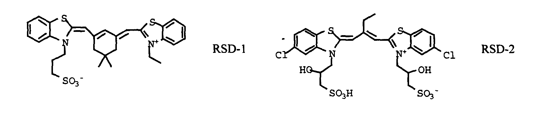
Useful sensitizing dyes include, but are not limited to, the following.
Emulsions can be spectrally sensitized with mixtures of two or
more sensitizing dyes which form mixed dye aggregates on the surface of the
emulsion grain. The use of mixed dye aggregates enables adjustment of the
spectral sensitivity of the emulsion to any wavelength between the extremes of the
wavelengths of peak sensitivities (λ-max) of the two or more dyes. This practice
is especially valuable if the two or more sensitizing dyes absorb in similar portions
of the spectrum (i.e., blue, or green or red and not green plus red or blue plus red
or green plus blue). Since the function of the spectral sensitizing dye is to
modulate the information recorded in the negative which is recorded as an image
dye, positioning the peak spectral sensitivity at or near the λ-max of the image dye
in the color negative produces the optimum preferred response. In addition, the
combination of similarly spectrally sensitized emulsions can be in one or more
layers.
An important quality characteristic of a reproductive film system is
color reproduction, which represents how accurately the hues of the original scene
are reproduced. Many current color papers use a blue sensitizing dye that gives a
maximum sensitivity at about 480 nm. Use of a sensitizing dye that affords a
sensitivity maximum that is closer to that of the yellow image dye in film, for
instance with a sensitivity maximum of around 450-470 nm, can result in a color
paper with improved color reproduction.
In the simplest contemplated form a recording element
contemplated for use in the electronic printing method of one embodiment of the
invention can consist of a single emulsion layer satisfying the emulsion
description provided above coated on a conventional photographic support, such
as those described in Research Disclosure, Item 38957, cited above, XVI.
Supports. In one preferred form the support is a white reflective support, such as
photographic paper support or a film support that contains or bears a coating of a
reflective pigment. To permit a print image to be viewed using an illuminant
placed behind the support, it is preferred to employ a white translucent support,
such as a Duratrans™ or Duraclear™ support.
Image dye-forming couplers may be included in the element such
as couplers that form cyan dyes upon reaction with oxidized color developing
agents which are described in such representative patents and publications as:
U.S. Patent Nos. 2,367,531; 2,423,730; 2,474,293; 2,772,162; 2,895,826;
3,002,836; 3,034,892; 3,041,236; 4,883,746 and "Farbkuppler - Eine Literature
Ubersicht," published in Agfa Mitteilungen, Band III, pp. 156-175 (1961).
Preferably such couplers are phenols and naphthols that form cyan dyes on
reaction with oxidized color developing agent. Also preferable are the cyan
couplers described in, for instance, European Patent Application Nos. 491,197;
544,322; 556,700; 556,777; 565,096; 570,006; and 574,948.
Typical cyan couplers are represented by the following formulas:
wherein R
1, R
5 and R
8 each represents a hydrogen or a substituent; R
2 represents
a substituent; R
3, R
4 and R
7 each represent an electron attractive group having a
Hammett's substituent constant σ
para of 0.2 or more and the sum of the σ
para
values of R
3 and R
4 is 0.65 or more; R
6 represents an electron attractive group
having a Hammett's substituent constant σ
para of 0.35 or more; X represents a
hydrogen or a coupling-off group; Z
1 represents nonmetallic atoms necessary for
forming a nitrogen-containing, six-membered, heterocyclic ring which has at least
one dissociative group; Z
2 represents ―C(R
7)= and -N=; and Z
3 and Z
4 each
represents ―C(R
8)= and -N=.
For purposes of this invention, an "NB coupler" is a dye-forming
coupler which is capable of coupling with the developer 4-amino-3-methyl-N-ethyl-N-(2-methanesulfonamidoethyl)
aniline sesquisulfate hydrate to form a dye
for which the left bandwidth (LBW) of its absorption spectra upon "spin coating"
of a 3% w/v solution of the dye in di-n-butyl sebacate solvent is at least 5 nm. less
than the LBW for a 3% w/v solution of the same dye in acetonitrile. The LBW of
the spectral curve for a dye is the distance between the left side of the spectral
curve and the wavelength of maximum absorption measured at a density of half
the maximum.
The "spin coating" sample is prepared by first preparing a solution
of the dye in di-n-butyl sebacate solvent (3% w/v). If the dye is insoluble,
dissolution is achieved by the addition of some methylene chloride. The solution
is filtered and 0.1-0.2ml is applied to a clear polyethylene terephthalate support
(approximately 4cm x 4cm) and spun at 4,000RPM using the Spin Coating
equipment, Model No. EC101, available from Headway Research Inc., Garland,
TX. The transmission spectra of the so prepared dye samples are then recorded.
Preferred "NB couplers" form a dye which, in n-butyl sebacate, has
a LBW of the absorption spectra upon "spin coating" which is at least 15 nm,
preferably at least 25 nm, less than that of the same dye in a 3% solution (w/v) in
acetonitrile.
In a preferred embodiment the cyan dye-forming "NB coupler"
useful in the invention has the formula (IA)
wherein
The coupler of formula (IA) is a 2,5-diamido phenolic cyan coupler
wherein the substituents R' and R" are preferably independently selected from
unsubstituted or substituted alkyl, aryl, amino, alkoxy and heterocyclyl groups.
In a further preferred embodiment, the "NB coupler" has the formula (I):
wherein
Typically, R" is an alkyl, amino or aryl group, suitably a phenyl
group. R"' is desirably an alkyl or aryl group or a 5-10 membered heterocyclic
ring which contains one or more heteroatoms selected from nitrogen, oxygen and
sulfur, which ring group is unsubstituted or substituted.
In the preferred embodiment the coupler of formula (I) is a 2,5-diamido
phenol in which the 5-amido moiety is an amide of a carboxylic acid
which is substituted in the alpha position by a particular sulfone (-SO2-) group,
such as, for example, described in U.S. Patent No. 5,686,235. The sulfone moiety
is an unsubstituted or substituted alkylsulfone or a heterocyclyl sulfone or it is an
arylsulfone, which is preferably substituted, in particular in the meta and/or para
position.
Couplers having these structures of formulae (I) or (IA) comprise
cyan dye-forming "NB couplers" which form image dyes having very sharp-cutting
dye hues on the short wavelength side of the absorption curves with
absorption maxima (λmax) which are shifted hypsochromically and are generally in
the range of 620-645 nm, which is ideally suited for producing excellent color
reproduction and high color saturation in color photographic papers.
Referring to formula (I), R1 and R2 are independently hydrogen or
an unsubstituted or substituted alkyl group, preferably having from 1 to 24 carbon
atoms and in particular 1 to 10 carbon atoms, suitably a methyl, ethyl, n-propyl,
isopropyl, butyl or decyl group or an alkyl group substituted with one or more
fluoro, chloro or bromo atoms, such as a trifluoromethyl group. Suitably, at least
one of R1 and R2 is a hydrogen atom and if only one of R1 and R2 is a hydrogen
atom then the other is preferably an alkyl group having 1 to 4 carbon atoms, more
preferably one to three carbon atoms and desirably two carbon atoms.
As used herein and throughout the specification unless where
specifically stated otherwise, the term "alkyl" refers to an unsaturated or saturated
straight or branched chain alkyl group, including alkenyl, and includes aralkyl and
cyclic alkyl groups, including cycloalkenyl, having 3-8 carbon atoms and the term
'aryl' includes specifically fused aryl.
In formula (I), R" is suitably an unsubstituted or substituted amino,
alkyl or aryl group or a 5-10 membered heterocyclic ring which contains one or
more heteroatoms selected from nitrogen, oxygen and sulfur, which ring is
unsubstituted or substituted, but is more suitably an unsubstituted or substituted
phenyl group.
Examples of suitable substituent groups for this aryl or heterocyclic
ring include cyano, chloro, fluoro, bromo, iodo, alkyl- or aryl-carbonyl, alkyl- or
aryl-oxycarbonyl, carbonamido, alkyl- or aryl-carbonamido, alkyl- or arylsulfonyl,
alkyl- or aryl-sulfonyloxy, alkyl- or aryl-oxysulfonyl, alkyl- or arylsulfoxide,
alkyl- or aryl-sulfamoyl, alkyl- or aryl-sulfonamido, aryl, alkyl, alkoxy,
aryloxy, nitro, alkyl- or aryl-ureido and alkyl- or aryl-carbamoyl groups, any of
which may be further substituted. Preferred groups are halogen, cyano,
alkoxycarbonyl, alkylsulfamoyl, alkyl-sulfonamido, alkylsulfonyl, carbamoyl,
alkylcarbamoyl or alkylcarbonamido. Suitably, R" is a 4-chlorophenyl, 3,4-dichlorophenyl,
3,4-difluorophenyl, 4-cyanophenyl, 3-chloro-4-cyanophenyl,
pentafluorophenyl, or a 3- or 4-sulfonamidophenyl group.
In formula (I), when R"' is alkyl, it may be unsubstituted or
substituted with a substituent such as halogen or alkoxy. When R"' is aryl or a
heterocycle, it may be substituted. Desirably it is not substituted in the position
alpha to the sulfonyl group.
In formula (I), when R"' is a phenyl group, it may be substituted in
the meta and/or para positions with one to three substituents independently
selected from the group consisting of halogen, and unsubstituted or substituted
alkyl, alkoxy, aryloxy, acyloxy, acylamino, alkyl- or aryl-sulfonyloxy, alkyl- or
aryl-sulfamoyl, alkyl- or aryl-sulfamoylamino, alkyl- or aryl-sulfonamido, alkyl-or
aryl-ureido, alkyl- or aryl-oxycarbonyl, alkyl- or aryl-oxy-carbonylamino and
alkyl- or aryl-carbamoyl groups.
In particular each substituent may be an alkyl group such as
methyl, t-butyl, heptyl, dodecyl, pentadecyl, octadecyl or 1,1,2,2-tetramethylpropyl;
an alkoxy group such as methoxy, t-butoxy, octyloxy,
dodecyloxy, tetradecyloxy, hexadecyloxy or octadecyloxy; an aryloxy group such
as phenoxy, 4-t-butylphenoxy or 4-dodecyl-phenoxy; an alkyl- or aryl-acyloxy
group such as acetoxy or dodecanoyloxy; an alkyl- or aryl-acylamino group such
as acetamido, hexadecanamido or benzamido; an alkyl- or aryl-sulfonyloxy group
such as methyl-sulfonyloxy, dodecylsulfonyloxy or 4-methylphenyl-sulfonyloxy;
an alkyl- or aryl-sulfamoyl-group such as N-butylsulfamoyl or N-4-t-butylphenylsulfamoyl;
an alkyl- or aryl-sulfamoylamino group such as N-butyl-sulfamoylamino
or N-4-t-butylphenylsulfamoyl-amino; an alkyl- or aryl-sulfonamido
group such as methane-sulfonamido, hexadecanesulfonamido or 4-chlorophenyl-sulfonamido;
an alkyl- or aryl-ureido group such as methylureido or
phenylureido; an alkoxy- or aryloxy-carbonyl such as methoxycarbonyl or
phenoxycarbonyl; an alkoxy- or aryloxy-carbonylamino group such as methoxy-carbonylamino
or phenoxycarbonylamino; an alkyl- or aryl-carbamoyl group such
as N-butylcarbamoyl or N-methyl-N-dodecylcarbamoyl; or a perfluoroalkyl group
such as trifluoromethyl or heptafluoropropyl.
Suitably the above substituent groups have 1 to 30 carbon atoms,
more preferably 8 to 20 aliphatic carbon atoms. A desirable substituent is an alkyl
group of 12 to 18 aliphatic carbon atoms such as dodecyl, pentadecyl or octadecyl
or an alkoxy group with 8 to 18 aliphatic carbon atoms such as dodecyloxy and
hexadecyloxy or a halogen such as a meta or para chloro group, carboxy or
sulfonamido. Any such groups may contain interrupting heteroatoms such as
oxygen to form e.g. polyalkylene oxides.
In formula (I) or (IA) Z is a hydrogen atom or a group which can be
split off by the reaction of the coupler with an oxidized color developing agent,
known in the photographic art as a 'coupling-off group' and may preferably be
hydrogen, chloro, fluoro, substituted aryloxy or mercaptotetrazole, more
preferably hydrogen or chloro.
The presence or absence of such groups determines the chemical
equivalency of the coupler, i.e., whether it is a 2-equivalent or 4-equivalent
coupler, and its particular identity can modify the reactivity of the coupler. Such
groups can advantageously affect the layer in which the coupler is coated, or other
layers in the photographic recording material, by performing, after release from
the coupler, functions such as dye formation, dye hue adjustment, development
acceleration or inhibition, bleach acceleration or inhibition, electron transfer
facilitation, color correction, and the like.
Representative classes of such coupling-off groups include, for
example, halogen, alkoxy, aryloxy, heterocyclyloxy, sulfonyloxy, acyloxy, acyl,
heterocyclylsulfonamido, heterocyclylthio, benzothiazolyl, phosophonyloxy,
alkylthio, arylthio, and arylazo. These coupling-off groups are described in the
art, for example, in U.S. Patent Nos. 2,455,169; 3,227,551; 3,432,521; 3,467,563;
3,617,291; 3,880,661; 4,052,212; and 4,134,766; and in U.K. Patent Nos. and
published applications 1,466,728; 1,531,927; 1,533,039; 2,066,755A, and
2,017,704A. Halogen, alkoxy and aryloxy groups are most suitable.
Examples of specific coupling-off groups are -Cl, -F, -Br, -SCN,-OCH
3,
-OC
6H
5, -OCH
2C(=O)NHCH
2CH
2OH, -OCH
2C(O)NHCH
2CH
2OCH
3,
-OCH
2C(O)NHCH
2CH
2OC(=O)OCH
3, -P(=O)(OC
2H
5)
2, -SCH
2CH
2C00H,
Typically, the coupling-off group is a chlorine atom, hydrogen
atom or p-methoxyphenoxy group.
It is essential that the substituent groups be selected so as to
adequately ballast the coupler and the resulting dye in the organic solvent in which
the coupler is dispersed. The ballasting may be accomplished by providing
hydrophobic substituent groups in one or more of the substituent groups.
Generally a ballast group is an organic radical of such size and configuration as to
confer on the coupler molecule sufficient bulk and aqueous insolubility as to
render the coupler substantially nondiffusible from the layer in which it is coated
in a photographic element. Thus the combination of substituent are suitably
chosen to meet these criteria. To be effective, the ballast will usually contain at
least 8 carbon atoms and typically contains 10 to 30 carbon atoms. Suitable
ballasting may also be accomplished by providing a plurality of groups which in
combination meet these criteria. In the preferred embodiments of the invention
R1 in formula (I) is a small alkyl group or hydrogen. Therefore, in these
embodiments the ballast would be primarily located as part of the other groups.
Furthermore, even if the coupling-off group Z contains a ballast it is often
necessary to ballast the other substituents as well, since Z is eliminated from the
molecule upon coupling; thus, the ballast is most advantageously provided as part
of groups other than Z.
The following examples further illustrate preferred coupler of the
invention. It is not to be construed that the present invention is limited to these
examples.
Preferred couplers are IC-3, IC-7, IC-35, and IC-36 because of their
suitably narrow left bandwidths.
Couplers that form magenta dyes upon reaction with oxidized color
developing agent are described in such representative patents and publications as:
U.S. Patent Nos. 2,311,082, 2,343,703, 2,369,489, 2,600,788, 2,908,573,
3,062,653, 3,152,896, 3,519,429, 3,758,309, and "Farbkuppler-eine Literature
Ubersicht," published in Agfa Mitteilungen, Band III, pp. 126-156 (1961).
Preferably such couplers are pyrazolones, pyrazolotriazoles, or
pyrazolobenzimidazoles that form magenta dyes upon reaction with oxidized color
developing agents. Especially preferred couplers are 1H-pyrazolo [5,1-c]-1,2,4-triazole
and 1H-pyrazolo [1,5-b]-1,2,4-triazole. Examples of 1H-pyrazolo [5,1-c]-1,2,4-triazole
couplers are described in U.K. Patent Nos. 1,247,493; 1,252,418;
1,398,979; U.S. Patent Nos. 4,443,536; 4,514,490; 4,540,654; 4,590,153;
4,665,015; 4,822,730; 4,945,034; 5,017,465; and 5,023,170. Examples of 1H-pyrazolo
[1,5-b]-1,2,4-triazoles can be found in European Patent applications
176,804; 177,765; U.S Patent Nos. 4,659,652; 5,066,575; and 5,250,400.
Typical pyrazoloazole and pyrazolone couplers are represented by the
following formulas:
wherein R
a and R
b independently represent H or a substituent; R
c is a substituent
(preferably an aryl group); R
d is a substituent (preferably an anilino, carbonamido,
ureido, carbamoyl, alkoxy, aryloxycarbonyl, alkoxycarbonyl, or
N-heterocyclic
group); X is hydrogen or a coupling-off group; and Z
a, Z
b, and Z
c are
independently a substituted methine group, =N-, =C-, or―NH―, provided
that one of either the Z
a―Z
b bond or the Z
b―Z
c bond is a double bond and the
other is a single bond, and when the Z
b―Z
c bond is a carbon-carbon double bond,
it may form part of an aromatic ring, and at least one of Z
a, Z
b, and Z
c represents
a methine group connected to the group R
b.
Specific examples of such couplers are:
Couplers that form yellow dyes upon reaction with oxidized color
developing agent are described in such representative patents and publications as:
U.S. Patent Nos. 2,298,443; 2,407,210; 2,875,057; 3,048,194; 3,265,506;
3,447,928; 3,960,570; 4,022,620; 4,443,536; 4,910,126; and 5,340,703 and
"Farbkuppler-eine Literature Ubersicht," published in Agfa Mitteilungen, Band
III, pp. 112-126 (1961). Such couplers are typically open chain ketomethylene
compounds. Also preferred are yellow couplers such as described in, for example,
European Patent Application Nos. 482,552; 510,535; 524,540; 543,367; and U.S.
Patent No. 5,238,803. For improved color reproduction, couplers which give
yellow dyes that cut off sharply on the long wavelength side are particularly
preferred (for example, see U.S. Patent No. 5,360,713).
Typical preferred yellow couplers are represented by the following
formulas:
wherein R
1, R
2, Q
1 and Q
2 each represents a substituent; X is hydrogen or a
coupling-off group; Y represents an aryl group or a heterocyclic group; Q
3
represents an organic residue required to form a nitrogen-containing heterocyclic
group together with the >N―; and Q
4 represents nonmetallic atoms necessary to
from a 3- to 5-membered hydrocarbon ring or a 3- to 5-membered heterocyclic
ring which contains at least one hetero atom selected from N, O, S, and P in the
ring. Particularly preferred is when Q
1 and Q
2 each represents an alkyl group, an
aryl group, or a heterocyclic group, and R
2 represents an aryl or tertiary alkyl
group.
Preferred yellow couplers can be of the following general structures
Unless otherwise specifically stated, substituent groups which may
be substituted on molecules herein include any groups, whether substituted or
unsubstituted, which do not destroy properties necessary for photographic utility.
When the term "group" is applied to the identification of a substituent containing a
substitutable hydrogen, it is intended to encompass not only the substituent's
unsubstituted form, but also its form further substituted with any group or groups
as herein mentioned. Suitably, the group may be halogen or may be bonded to the
remainder of the molecule by an atom of carbon, silicon, oxygen, nitrogen,
phosphorous, or sulfur. The substituent may be, for example, halogen, such as
chlorine, bromine or fluorine; nitro; hydroxyl; cyano; carboxyl; or groups which
may be further substituted, such as alkyl, including straight or branched chain
alkyl, such as methyl, trifluoromethyl, ethyl, t-butyl, 3-(2,4-di-t-pentylphenoxy)
propyl, and tetradecyl; alkenyl, such as ethylene, 2-butene; alkoxy, such as
methoxy, ethoxy, propoxy, butoxy, 2-methoxyethoxy, sec-butoxy, hexyloxy, 2-ethylhexyloxy,
tetradecyloxy, 2-(2,4-di-t-pentylphenoxy)ethoxy, and 2-dodecyloxyethoxy;
aryl such as phenyl, 4-t-butylphenyl, 2,4,6-trimethylphenyl,
naphthyl; aryloxy, such as phenoxy, 2-methylphenoxy, alpha- or beta-naphthyloxy,
and 4-tolyloxy; carbonamido, such as acetamido, benzamido,
butyramido, tetradecanamido, alpha-(2,4-di-t-pentyl-phenoxy)acetamido, alpha-(2,4-di-t-pentylphenoxy)butyramido,
alpha-(3-pentadecylphenoxy)-hexanamido,
alpha-(4-hydroxy-3-t-butylphenoxy)-tetradecanamido, 2-oxo-pyrrolidin-1-yl, 2-oxo-5-tetradecylpyrrolin-1-yl,
N-methyltetradecanamido, N-succinimido, N-phthalimido,
2,5-dioxo-1-oxazolidinyl, 3-dodecyl-2,5-dioxo-1-imidazolyl, and N-acetyl-N-dodecylamino,
ethoxycarbonylamino, phenoxycarbonylamino,
benzyloxycarbonylamino, hexadecyloxycarbonylamino, 2,4-di-t-butylphenoxycarbonylamino,
phenylcarbonylamino, 2,5-(di-t-pentylphenyl)carbonylamino,
p-dodecyl-phenylcarbonylamino, p-toluylcarbonylamino,
N-methylureido, N,N-dimethylureido, N-methyl-N-dodecylureido,
N-hexadecylureido, N,N-dioctadecylureido, N,N-dioctyl-N'-ethylureido,
N-phenylureido, N,N-diphenylureido, N-phenyl-N-p-toluylureido, N-(m-hexadecylphenyl)ureido,
N,N-(2,5-di-t-pentylphenyl)-N'-ethylureido, and t-butylcarbonamido;
sulfonamido, such as methylsulfonamido,
benzenesulfonamido, p-toluylsulfonamido, p-dodecylbenzenesulfonamido, N-methyltetradecylsulfonamido,
N,N-dipropyl-sulfamoylamino, and
hexadecylsulfonamido; sulfamoyl, such as N-methylsulfamoyl, N-ethylsulfamoyl,
N,N-dipropylsulfamoyl, N-hexadecylsulfamoyl, N,N-dimethylsulfamoyl; N-[3-(dodecyloxy)propyl]sulfamoyl,
N-[4-(2,4-di-t-pentylphenoxy)butyl]sulfamoyl, N-methyl-N-tetradecylsulfamoyl,
and N-dodecylsulfamoyl; carbamoyl, such as N-methylcarbamoyl,
N,N-dibutylcarbamoyl, N-octadecylcarbamoyl, N-[4-(2,4-di-t-pentylphenoxy)butyl]carbamoyl,
N-methyl-N-tetradecylcarbamoyl, and N,N-dioctylcarbamoyl;
acyl, such as acetyl, (2,4-di-t-amylphenoxy)acetyl,
phenoxycarbonyl, p-dodecyloxyphenoxycarbonyl, methoxycarbonyl,
butoxycarbonyl, tetradecyloxycarbonyl, ethoxycarbonyl, benzyloxycarbonyl, 3-pentadecyloxycarbonyl,
and dodecyloxycarbonyl; sulfonyl, such as
methoxysulfonyl, octyloxysulfonyl, tetradecyloxysulfonyl, 2-ethylhexyloxysulfonyl,
phenoxysulfonyl, 2,4-di-t-pentylphenoxysulfonyl,
methylsulfonyl, octylsulfonyl, 2-ethylhexylsulfonyl, dodecylsulfonyl,
hexadecylsulfonyl, phenylsulfonyl, 4-nonylphenylsulfonyl, and p-toluylsulfonyl;
sulfonyloxy, such as dodecylsulfonyloxy, and hexadecylsulfonyloxy; sulfinyl,
such as methylsulfinyl, octylsulfinyl, 2-ethylhexylsulfinyl, dodecylsulfinyl,
hexadecylsulfinyl, phenylsulfinyl, 4-nonylphenylsulfinyl, and p-toluylsulfinyl;
thio, such as ethylthio, octylthio, benzylthio, tetradecylthio, 2-(2,4-di-t-pentylphenoxy)ethylthio,
phenylthio, 2-butoxy-5-t-octylphenylthio, and p-tolylthio;
acyloxy, such as acetyloxy, benzoyloxy, octadecanoyloxy, p-dodecylamidobenzoyloxy,
N-phenylcarbamoyloxy, N-ethylcarbamoyloxy, and
cyclohexylcarbonyloxy; amino, such as phenylanilino, 2-chloroanilino,
diethylamino, dodecylamino; imino, such as 1 (N-phenylimido)ethyl, N-succinimido
or 3-benzylhydantoinyl; phosphate, such as dimethylphosphate and
ethylbutylphosphate; phosphite, such as diethyl and dihexylphosphite; a
heterocyclic group, a heterocyclic oxy group or a heterocyclic thio group, each of
which may be substituted and which contain a 3 to 7 membered heterocyclic ring
composed of carbon atoms and at least one hetero atom selected from the group
consisting of oxygen, nitrogen and sulfur, such as 2-furyl, 2-thienyl, 2-benzimidazolyloxy
or 2-benzothiazolyl; quaternary ammonium, such as
triethylammonium; and silyloxy, such as trimethylsilyloxy.
If desired, the substituents may themselves be further substituted
one or more times with the described substituent groups. The particular
substituents used may be selected by those skilled in the art to attain the desired
photographic properties for a specific application and can include, for example,
hydrophobic groups, solubilizing groups, blocking groups, releasing or releasable
groups, etc. Generally, the above groups and substituents thereof may include
those having up to 48 carbon atoms, typically 1 to 36 carbon atoms and usually
less than 24 carbon atoms, but greater numbers are possible depending on the
particular substituents selected.
Representative substituents on ballast groups include alkyl, aryl,
alkoxy, aryloxy, alkylthio, hydroxy, halogen, alkoxycarbonyl, aryloxcarbonyl,
carboxy, acyl, acyloxy, amino, anilino, carbonamido, carbamoyl, alkylsulfonyl,
arylsulfonyl, sulfonamido, and sulfamoyl groups wherein the substituents
typically contain 1 to 42 carbon atoms. Such substituents can also be further
substituted.
Stabilizers and scavengers that can be used in these photographic
elements, but are not limited to, the following.
Examples of solvents which may be used in the invention include the following:
| Tritolyl phosphate | S-1 |
| Dibutyl phthalate | S-2 |
| Diundecyl phthalate | S-3 |
| N,N-Diethyldodecanamide | S-4 |
| N,N-Dibutyldodecanamide | S-5 |
| Tris(2-ethylhexyl)phosphate | S-6 |
| Acetyl tributyl citrate | S-7 |
| 2,4-Di-tert-pentylphenol | S-8 |
| 2-(2-Butoxyethoxy)ethyl acetate | S-9 |
| 1,4-Cyclohexyldimethylene bis(2-ethylhexanoate) | S-10 |
The dispersions used in photographic elements may also include
ultraviolet (UV) stabilizers and so called liquid UV stabilizers such as described in
U.S. Patent Nos. 4,992,358; 4,975,360; and 4,587,346. Examples of UV
stabilizers are shown below.
The aqueous phase may include surfactants. Surfactant may be
cationic, anionic, zwitterionic or non-ionic. Useful surfactants include, but are not
limited to, the following:
Further, it is contemplated to stabilize photographic dispersions
prone to particle growth through the use of hydrophobic, photographically inert
compounds such as disclosed by Zengerle et al in U.S. Patent 5,468,604.
The photographic elements may also contain filter dye layers
comprising colloidal silver sol or yellow, cyan, and/or magenta filter dyes, either
as oil-in-water dispersions, latex dispersions or as solid particle dispersions.
Useful examples of absorbing materials are discussed in Research Disclosure,
September 1996, Item 38957, Section VIII.
The photographic elements may also contain light absorbing
materials that can increase sharpness and be used to control speed and minimum
density. Examples of useful absorber dyes are described in U.S. Patent Nos.
4,877,721; 5,001,043; 5,153,108; and 5,035,985. Solid particle dispersion dyes
are described in U.S. Patent Nos. 4,803,150; 4,855,221; 4,857,446; 4,900,652;
4,900,653; 4,940,654; 4,948,717; 4,948,718; 4,950,586; 4,988,611; 4,994,356;
5,098,820; 5,213,956; 5,260,179; and 5,266,454. Useful dyes include, but are not
limited to, the following.
In a preferred embodiment the invention employs recording
elements which are constructed to contain at least three silver halide emulsion
layer units. A suitable full color, multilayer format for a recording element used
in the invention is represented by Structure I.
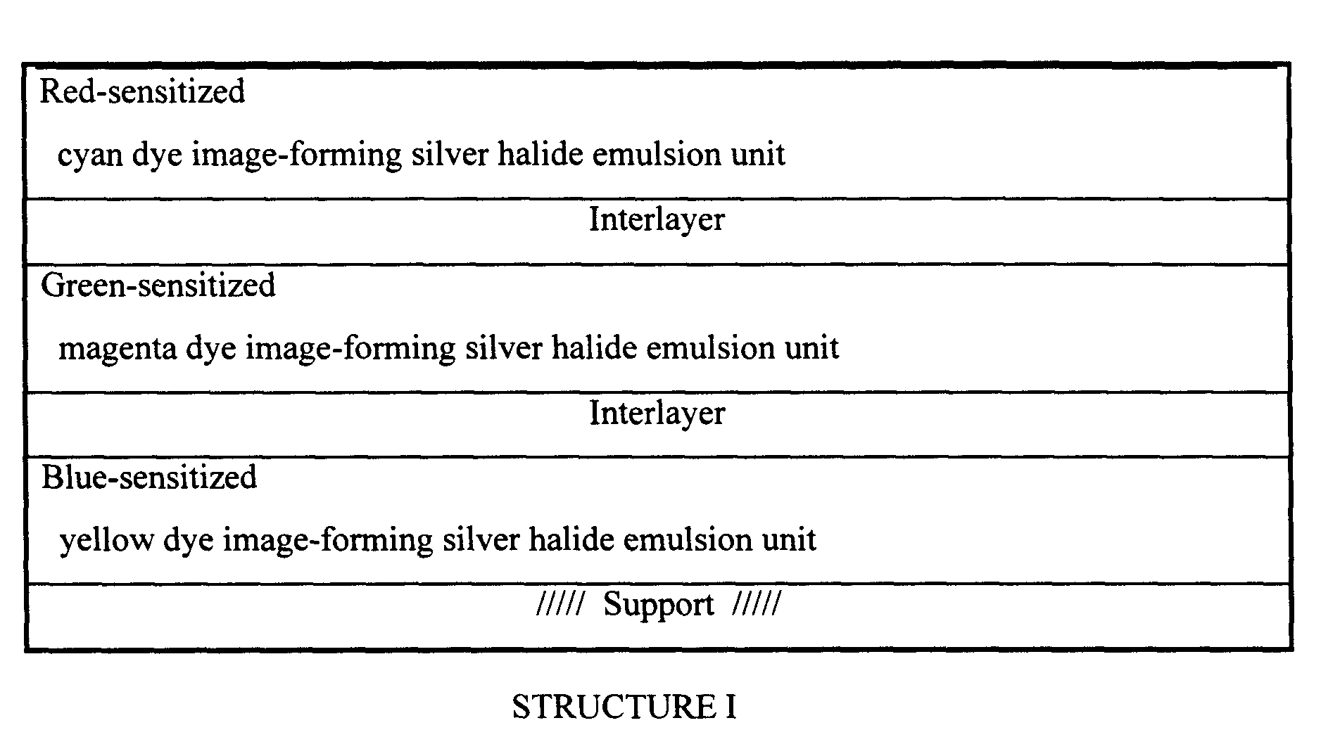
wherein the red-sensitized, cyan dye image-forming silver halide emulsion unit is
situated nearest the support; next in order is the green-sensitized, magenta dye
image-forming unit, followed by the uppermost blue-sensitized, yellow dye
image-forming unit. The image-forming units are separated from each other by
hydrophilic colloid interlayers containing an oxidized developing agent scavenger
to prevent color contamination. Silver halide emulsions satisfying the grain and
gelatino-peptizer requirements described above can be present in any one or
combination of the emulsion layer units. Additional useful multicolor, multilayer
formats for an element of the invention include structures as described in U.S.
Patent 5,783,373. Each of such structures in accordance with the invention
preferably would contain at least three silver halide emulsions comprised of high
chloride grains having at least 50 percent of their surface area bounded by {100}
crystal faces and containing dopants from classes (i) and (ii), as described above.
Preferably each of the emulsion layer units contains emulsion satisfying these
criteria.
In a more preferred embodiment, the invention employs recording
elements which are constructed as described in U.S. Patent 5,948,601 of Rieger.
In this embodiment, the invention employs recording elements which are
constructed to contain at least three silver halide emulsion layer units and an
interlayer adjacent to the blue sensitive emulsion layer
Conventional features that can be incorporated into multilayer (and
particularly multicolor) recording elements contemplated for use in the method of
the invention are illustrated by
Research Disclosure, Item 38957, cited above:
The recording elements comprising the radiation sensitive high
chloride emulsion layers according to this invention can be conventionally
optically printed, or in accordance with a particular embodiment of the invention
can be image-wise exposed in a pixel-by-pixel mode using suitable high energy
radiation sources typically employed in electronic printing methods. Suitable
actinic forms of energy encompass the ultraviolet, visible and infrared regions of
the electromagnetic spectrum as well as electron-beam radiation and is
conveniently supplied by beams from one or more light emitting diodes or lasers,
including gaseous or solid state lasers. Exposures can be monochromatic,
orthochromatic or panchromatic. For example, when the recording element is a
multilayer multicolor element, exposure can be provided by laser or light emitting
diode beams of appropriate spectral radiation, for example, infrared, red, green or
blue wavelengths, to which such element is sensitive. Multicolor elements can be
employed which produce cyan, magenta, and yellow dyes as a function of
exposure in separate portions of the electromagnetic spectrum, including at least
two portions of the infrared region, as disclosed in the previously mentioned U.S.
Patent No. 4,619,892. Suitable exposures include those up to 2000 nm, preferably
up to 1500 nm. Suitable light emitting diodes and commercially available laser
sources are known and commercially available. Imagewise exposures at ambient,
elevated or reduced temperatures and/or pressures can be employed within the
useful response range of the recording element determined by conventional
sensitometric techniques, as illustrated by T.H. James, The Theory of the
Photographic Process, 4th Ed., Macmillan, 1977, Chapters 4, 6, 17, 18 and 23.
It has been observed that anionic [MXxYyLz] hexacoordination
complexes, where M is a group 8 or 9 metal (preferably iron, ruthenium or
iridium), X is halide or pseudohalide (preferably Cl, Br or CN) x is 3 to 5, Y is
H2O, y is 0 or 1, L is a C-C, H-C or C-N-H organic ligand, and Z is 1 or 2, are
surprisingly effective in reducing high intensity reciprocity failure (HIRF), low
intensity reciprocity failure (LIRF) and thermal sensitivity variance and in in
improving latent image keeping (LIK). As herein employed HIRF is a measure of
the variance of photographic properties for equal exposures, but with exposure
times ranging from 10-1 to 10-6 second. LIRF is a measure of the variance of
photographic properties for equal exposures, but with exposure times ranging
from 10-1 to 100 seconds. Although these advantages can be generally compatible
with face centered cubic lattice grain structures, the most striking improvements
have been observed in high (>50 mole %, preferably ≥90 mole %) chloride
emulsions. Preferred C-C, H-C or C-N-H organic ligands are aromatic
heterocycles of the type described in U.S. Patent No. 5,462,849. The most
effective C-C, H-C or C-N-H organic ligands are azoles and azines, either
unsustituted or containing alkyl, alkoxy or halide substituents, where the alkyl
moieties contain from 1 to 8 carbon atoms. Particularly preferred azoles and
azines include thiazoles, thiazolines, and pyrazines.
The quantity or level of high energy actinic radiation provided to
the recording medium by the exposure source is generally at least 10-4 ergs/cm2,
typically in the range of about 10-4 ergs/cm2 to 10-3 ergs/cm2 and often from 10-3
ergs/cm2 to 102 ergs/cm2. Exposure of the recording element in a pixel-by-pixel
mode as known in the prior art persists for only a very short duration or time.
Typical maximum exposure times are up to 100 µ seconds, often up to 10 µ
seconds, and frequently up to only 0.5 µ seconds. Single or multiple exposures of
each pixel are contemplated. The pixel density is subject to wide variation, as is
obvious to those skilled in the art. The higher the pixel density, the sharper the
images can be, but at the expense of equipment complexity. In general, pixel
densities used in conventional electronic printing methods of the type described
herein do not exceed 107 pixels/cm2 and are typically in the range of about 104 to
106 pixels/cm2. An assessment of the technology of high-quality, continuous-tone,
color electronic printing using silver halide photographic paper which discusses
various features and components of the system, including exposure source,
exposure time, exposure level and pixel density and other recording element
characteristics is provided in Firth et al., A Continuous-Tone Laser Color Printer,
Journal of Imaging Technology, Vol. 14, No. 3, June 1988. As previously
indicated herein, a description of some of the details of conventional electronic
printing methods comprising scanning a recording element with high energy
beams such as light emitting diodes or laser beams, are set forth in Hioki U.S.
Patent 5,126,235, European Patent Applications 479 167 A1 and 502 508 A1.
Once imagewise exposed, the recording elements can be processed
in any convenient conventional manner to obtain a viewable image. Such
processing is illustrated by
Research Disclosure, Item 38957, cited above:
In addition, a useful developer for the inventive material is a
homogeneous, single part developing agent. The homogeneous, single-part color
developing concentrate is prepared using a critical sequence of steps:
In the first step, an aqueous solution of a suitable color developing
agent is prepared. This color developing agent is generally in the form of a sulfate
salt. Other components of the solution can include an antioxidant for the color
developing agent, a suitable number of alkali metal ions (in an at least
stoichiometric proportion to the sulfate ions) provided by an alkali metal base, and
a photographically inactive water-miscible or water-soluble hydroxy-containing
organic solvent. This solvent is present in the final concentrate at a concentration
such that the weight ratio of water to the organic solvent is from about 15:85 to
about 50:50.
In this environment, especially at high alkalinity, alkali metal ions
and sulfate ions form a sulfate salt that is precipitated in the presence of the
hydroxy-containing organic solvent. The precipitated sulfate salt can then be
readily removed using any suitable liquid/solid phase separation technique
(including filtration, centrifugation or decantation). If the antioxidant is a liquid
organic compound, two phases may be formed and the precipitate may be
removed by discarding the aqueous phase.
The color developing concentrates of this invention include one
or more color developing agents that are well known in the art that, in oxidized
form, will react with dye forming color couplers in the processed materials.
Such color developing agents include, but are not limited to, aminophenols, p-phenylenediamines
(especially N,N-dialkyl-p-phenylenediamines) and others
which are well known in the art, such as EP 0 434 097 A1 (published June 26,
1991) and EP 0 530 921 A1 (published March 10, 1993). It may be useful for
the color developing agents to have one or more water-solubilizing groups as are
known in the art. Further details of such materials are provided in Research
Disclosure, publication 38957, pages 592-639 (September 1996). Research
Disclosure is a publication of Kenneth Mason Publications Ltd., Dudley House,
12 North Street, Emsworth, Hampshire PO10 7DQ England (also available from
Emsworth Design Inc., 121 West 19th Street, New York, N.Y. 10011).
Preferred color developing agents include, but are not limited to,
N,N-diethyl p-phenylenediamine sulfate (KODAK Color Developing Agent
CD-2), 4-amino-3-methyl-N-(2-methane sulfonamidoethyl)aniline sulfate, 4-(N-ethyl-N-β-hydroxyethylamino)-2-methylaniline
sulfate (KODAK Color
Developing Agent CD-4), p-hydroxyethylethylaminoaniline sulfate, 4-(N-ethyl-N-2-methanesulfonylaminoethyl)-2-methylphenylenediamine
sesquisulfate
(KODAK Color Developing Agent CD-3), 4-(N-ethyl-N-2-methanesulfonylaminoethyl)-2-methylphenylenediamine
sesquisulfate, and
others readily apparent to one skilled in the art.
In order to protect the color developing agents from oxidation, one
or more antioxidants are generally included in the color developing compositions.
Either inorganic or organic antioxidants can be used. Many classes of useful
antioxidants are known, including but not limited to, sulfites (such as sodium
sulfite, potassium sulfite, sodium bisulfite and potassium metabisulfite),
hydroxylamine (and derivatives thereof), hydrazines, hydrazides, amino acids,
ascorbic acid (and derivatives thereof), hydroxamic acids, aminoketones, mono-and
polysaccharides, mono- and polyamines, quaternary ammonium salts, nitroxy
radicals, alcohols, and oximes. Also useful as antioxidants are 1,4-cyclohexadiones.
Mixtures of compounds from the same or different classes of
antioxidants can also be used if desired.
Especially useful antioxidants are hydroxylamine derivatives as
described, for example, in U.S. Patent Nos. 4,892,804; 4,876,174; 5,354,646; and
5,660,974, all noted above, and U.S. 5,646,327 (Burns et al). Many of these
antioxidants are mono- and dialkylhydroxylamines having one or more
substituents on one or both alkyl groups. Particularly useful alkyl substituents
include sulfo, carboxy, amino, sulfonamido, carbonamido, hydroxy and other
solubilizing substituents.
More preferably, the noted hydroxylamine derivatives can be
mono- or dialkylhydroxylamines having one or more hydroxy substituents on the
one or more alkyl groups. Representative compounds of this type are described
for example in U.S. Patent 5,709,982 (Marrese et al) as having the structure I:
wherein R is hydrogen, a substituted or unsubstituted alkyl group of 1 to 10
carbon atoms, a substituted or unsubstituted hydroxyalkyl group of 1 to 10 carbon
atoms, a substituted or unsubstituted cycloalkyl group of 5 to 10 carbon atoms, or
a substituted or unsubstituted aryl group having 6 to 10 carbon atoms in the
aromatic nucleus.
X1 is -CR2(OH)CHR1- and X2 is -CHR1CR2(OH)- wherein R1 and
R2 are independently hydrogen, hydroxy, a substituted or unsubstituted alkyl
group or 1 or 2 carbon atoms, a substituted or unsubstituted hydroxyalkyl group of
1 or 2 carbon atoms, or R1 and R2 together represent the carbon atoms necessary to
complete a substituted or unsubstituted 5- to 8-membered saturated or unsaturated
carbocyclic ring structure.
Y is a substituted or unsubstituted alkylene group having at least 4
carbon atoms, and has an even number of carbon atoms, or Y is a substituted or
unsubstituted divalent aliphatic group having an even total number of carbon and
oxygen atoms in the chain, provided that the aliphatic group has a least 4 atoms in
the chain.
Also in Structure I, m, n and p are independently 0 or 1.
Preferably, each of m and n is 1, and p is 0.
Specific di-substituted hydroxylamine antioxidants include, but are
not limited to: N,N-bis(2,3-dihydroxypropyl)hydroxylamine, N,N-bis(2-methyl-2,3-dihydroxypropyl)hydroxylamine
and N,N-bis(1-hydroxymethyl-2-hydroxy-3-phenylpropyl)hydroxylamine.
The first compound is preferred.
The following examples illustrate the practice of this invention.
They are not intended to be exhaustive of all possible variations of the invention.
Parts and percentages are by weight unless otherwise indicated.
EXAMPLES
Example 1
In this example the color silver halide emulsion of the invention
was coated on two imaging support materials. The first support material of the
invention was constructed by laminating biaxially oriented sheets to cellulose
photographic grade paper. The second support material, which is the control
material, was constructed by melt extrusion coating with low density polyethylene
cellulose photographic grade paper. The control material is typical of prior art
photographic support materials. This example will show the improvement the
invention has made compared to the control in digital printing. Further, this
example will also demonstrate the image sharpness, whiteness, and durability
improvement over prior art photographic base materials.
The support material utilized in the control consisted of melt
extruded low density polyethylene applied to a photographic grade cellulose paper
base. The low density polyethylene on the topside of the control support contains
blue tint, anatase TiO2 and optical brightener. The control support structure is
typical of prior art color photographic base materials.
The following is a description of the invention and was prepared by
extrusion laminating the following top and bottom biaxially oriented sheets to the
photographic grade cellulose paper described below:
Top Sheet (Emulsion side):
A composite sheet consisting of 5 layers identified as L1, L2, L3,
L4, and L5. L1 is the thin colored layer on the outside of the package to which the
photosensitive silver halide layer was attached. L2 is the layer to which optical
brightener and TiO
2 was added. The optical brightener used was Hostalux KS
manufactured by Ciba-Geigy. A coated extrusion grade anatase TiO
2 was added
to both L2 and L4. Table 1 below lists the characteristics of the layers of the top
biaxially oriented sheet used in this example.
| Layer | Material | Thickness, µm |
| L1 | LD Polyethylene + color concentrate | 0.65 |
| L2 | Polypropylene + 24% TiO2 + OB | 6.75 |
| L3 | Voided Polypropylene | 30 |
| L4 | Polypropylene + 18% TiO2 | 6.90 |
| L5 | Polypropylene | 0.66 |
Paper base was produced for the invention using a standard
fourdrinier paper machine and a blend of mostly bleached hardwood Kraft fibers.
The fiber ratio consisted primarily of bleached poplar (38%) and maple/beech
(37%) with lesser amounts of birch (18%) and softwood (7%). Fiber length was
reduced from 0.73 mm length weighted average as measured by a Kajaani FS-200
to 0.55 mm length using high levels of conical refining and low levels of disc
refining. Fiber Lengths from the slurry were measured using an FS-200 Fiber
Length Analyzer (Kajaani Automation Inc. ). Energy applied to the fibers is
indicated by the total Specific Net Refining Power (SNRP) was 127 KW hr/metric
ton. Two conical refiners were used in series to provide the total conical refiners
SNRP value. This value was obtained by adding the SNRPs of each conical
refiner. Two disc refiners were similarly used in series to provide a total Disk
SNRP. Neutral sizing chemical addenda, utilized on a dry weight basis, included
alkyl ketene dimer at 0.20% addition, cationic starch (1.0%), polyaminoamide
epichlorhydrin (0.50%), polyacrylamide resin (0.18%), diaminostilbene optical
brightener (0.20 %), and sodium bicarbonate. Surface sizing using
hydroxyethylated starch and sodium chloride was also employed but is not critical
to the invention. In the 3rd Dryer section, ratio drying was utilized to provide a
moisture bias from the face side to the wire side of the sheet. The face side
(emulsion side) of the sheet was then remoisturized with conditioned steam
immediately prior calendering. Sheet temperatures were raised to between 76°C
and 93°C just prior to and during calendering. The paper was then calendered to
an apparent density of 1.17. Moisture levels after the calender were 7.0% to 9.0%
by weight. Paper base B was produced at a thickness of 254 micrometers.
Bottom Sheet (Backside):
The bottom biaxially oriented sheet laminated to the backside of
invention base was a one-side matte finish, biaxially oriented polypropylene sheet
(25.6 µm thick) (d = 0.90 g/cc) consisting of a solid oriented polypropylene layer
and a skin layer of a mixture of polyethylenes and a terpolymer comprising
ethylene, propylene, and butylene. The skin layer was on the bottom, and the
polypropylene layer was laminated to the paper.
The top sheet used in this example was coextruded and biaxially
oriented. The top sheet was melt extrusion laminated to the above cellulose paper
base using a metallocene catalyzed ethylene plastomer (SLP 9088) manufactured
by Exxon Chemical Corp. The metallocene catalyzed ethylene plastomer had a
density of 0.900 g/cc and a melt index of 14.0.
A coating was then applied to the laminated bottom biaxially
oriented sheet on invention using a gravure coater to add the high frequency
roughness to the backside. The coating consisted of an aqueous solution
containing a sodium salt of styrene sulfonic acid dispersed in an acrylate latex.
The coverage used was 25 mg per square meter and then dried to achieve a final
web temperature between 55°C, the resultant coalesced latex material produced
the desired high frequency roughness pattern. In addition to the sodium salt of
styrene sulfonic acid, aluminum modified colloidal silicon dioxide particles were
added to the aqueous latex material at a concentration of 50 milligrams per square
meter. This further enhanced the high frequency roughness.
The L3 layer for the biaxially oriented sheet is microvoided and
further described in Table 2 where the refractive index and geometrical thickness
is shown for measurements made along a single slice through the L3 layer; they do
not imply continuous layers, a slice along another location would yield different
but approximately the same thickness. The areas with a refractive index of 1.0 are
voids that are filled with air and the remaining layers are polypropylene.
| Sublayer of L3 | Refractive Index | Thickness, µm |
| 1 | 1.49 | 2.54 |
| 2 | 1 | 2.027 |
| 3 | 1.49 | 2.79 |
| 4 | 1 | 2.016 |
| 5 | 1.49 | 1.778 |
| 6 | 1 | 2.016 |
| 7 | 1.49 | 2.286 |
| 8 | 1 | 2.016 |
| 9 | 1.49 | 2.032 |
| 10 | 1 | 0.762 |
| 11 | 1.49 | 2.032 |
| 12 | 1 | 2.016 |
| 13 | 1.49 | 2.278 |
| 14 | 1 | 2.016 |
| 15 | 1.49 | 2.286 |
Silver chloride emulsions were chemically and spectrally sensitized
as described below. A biocide comprising a mixture of N-methyl-isothiazolone
and N-methyl-5-chloro-isthiazolone was added after sensitization.
Blue Sensitive Emulsion (Blue EM-1).
A high chloride silver halide emulsion is
precipitated by adding approximately equimolar silver nitrate and sodium chloride
solutions into a well-stirred reactor containing p-glutaryldiaminophenyldisulfide,
gelatin peptizer, and thioether ripener. Cesium pentachloronitrosylosmate(II)
dopant is added during the silver halide grain formation from 3.9% to 70% of the
making process, followed by the addition of potassium hexacyanoruthenate(II) at
75-80% of the make and potassium (5-methylthiazole)-pentachloroiridate from 92-95%
of the make. In addition, potassium iodide was added at 90% +/-3% of the
making process to form a band of silver iodide at 0.2% +/-0.1% of the silver in the
grain. The resultant emulsion contains cubic shaped grains having edge length of
0.64µm.The emulsion is optimally sensitized by the addition of p-glutaryldiaminophenyldisulfide
followed by a colloidal suspension of aurous
sulfide and heat ramped to 60°C. After the temperature reached 60°C, blue
sensitizing dye BSD-4, potassium hexchloroiridate, Lippmann bromide, and 1-(3-acetamidophenyl)-5-mercaptotetrazole
were added.
Green Sensitive Emulsion (Green EM-1):
A high chloride silver halide
emulsion is precipitated by adding approximately equimolar silver nitrate and
sodium chloride solutions, the silver nitrate solution containing
p-glutaryldiaminophenyldisulfide, into a well-stirred reactor containing gelatin
peptizer and thioether ripener. Cesium pentachloronitrosylosmate(II) dopant is
added from 1.5% to 75% of the silver halide grain formation, followed by the
addition of potassium (5-methylthiazole)-pentachloroiridate from 90-95% of the
precipitation. The resultant emulsion contains cubic shaped grains of 0.34 µm in
edgelength size. The emulsion is optimally sensitized by the addition of a liquid
crystalline suspension of green sensitizing dye GSD-1 and a colloidal suspension
of aurous sulfide followed by heating to 60°C. for 35 minutes. After cooling to
40°C, an antifoggant 1-(3-acetamidophenyl)-5-mercaptotetrazole, potassium
bromide, and potassium chloride were added.
Red Sensitive Emulsion (Red EM-1):
A high chloride silver halide emulsion is
precipitated by adding approximately equimolar silver nitrate and sodium chloride
solutions into a well-stirred reactor containing gelatin peptizer and thioether
ripener. During the silver halide grain formation, cesium
pentachloronitrosylosmate, potassium hexacyanoruthenate(II) and potassium (5-methylthiazole)-pentachloroiridate
are added from 3-75%, 80-85% and 90-95% of
the precipitation, respectively. The resultant emulsion contains cubic shaped
grains of 0.38 µm in edgelength size. The emulsion is optimally sensitized by the
addition of glutaryldiaminophenyldisulfide, sodium thiosulfate and Bis(1,4,5-trimethyl-1,2,4-triazolium-3-thiolate)gold(I)fluoroborate.
After heating to 65°C.
this emulsion was held for 28 minutes, and then the following were added: 1-(3-acetamidophenyl)-5-mercaptotetrazole,
potassium hexachloroiridate, and
potassium bromide. The emulsion is then cooled to 40°C and red sensitizing dye
RSD-1 is added.
Coupler dispersions were emulsified by methods well known to the
art, and the following layers were coated on the following support:
The following light sensitive silver halide imaging layers were
utilized to prepare photographic print materials for the invention. The following
imaging layers were coated utilizing curtain coating.
| | Item | Laydown g/m2 |
| Layer 1 | Blue Sensitive Layer |
| | Gelatin | 1.3885 |
| | Blue Sensitive silver (Blue EM-1) | 0.2799 |
| | Y-5 | 0.4521 |
| | ST-6 | 0.0775 |
| | ST-7 | 0.0258 |
| | S-3 | 0.1981 |
| | Piperidino hexose reductone | 0.0023 |
| | Sodium phenylmercaptotetrazole | 0.0001 |
| | DYE-1 | 0.0323 |
| Layer 2 | Split Yellow Interlayer |
| | Gelatin | 0.3229 |
| | Y-5 | 0.1938 |
| | ST-6 | 0.0332 |
| | ST-7 | 0.0111 |
| | S-3 | 0.0849 |
| Layer 3 | Interlayer |
| | Gelatin | 0.7535 |
| | ST-4 | 0.0660 |
| | S-2 | 0.1884 |
| | Acrylamide/t-Butylacrylamide sulfonate copolymer | 0.1281 |
| | Bis-vinylsulfonylmethane | 0.0151 |
| Layer 4 | Green Sensitive Layer |
| | Gelatin | 1.3498 |
| | Green Sensitive silver (Green EM-1) | 0.1076 |
| | M-2 | 0.2142 |
| | S-2 | 0.0761 |
| | S-3 | 0.0326 |
| | ST-8 | 0.0560 |
| | ST-21 | 0.1636 |
| | DYE-2 | 0.0075 |
| | Sodium phenylmercaptotetrazole | 0.0003 |
| Layer 5 | UV Interlayer |
| | Gelatin | 0.7136 |
| | UV-1 | 0.0312 |
| | UV-2 | 0.1722 |
| | ST-4 | 0.0527 |
| | S-10 | 0.0344 |
| | S-2 | 0.0344 |
| Layer 6 | Red Sensitive Layer |
| | Gelatin | 1.3563 |
| | Red sensitive silver (Red EM-1) | 0.1938 |
| | C-1 | 0.4004 |
| | S-2 | 0.3918 |
| | UV-2 | 0.2573 |
| | S-9 | 0.0328 |
| | ST-4 | 0.0033 |
| | DYE-3 | 0.0151 |
| | Potassium tolylthiosulfonate | 0.0027 |
| | Potassium tolylsulfinate | 0.0003 |
| Layer 7 | UV Overcoat |
| | Gelatin | 0.5350 |
| | UV-1 | 0.0229 |
| | UV-2 | 0.1301 |
| | ST-4 | 0.0384 |
| | S-10 | 0.0255 |
| | S-2 | 0.0255 |
| Layer 8 | SOC |
| | Gelatin | 0.6458 |
| | Ludox AM™ (colloidal silica) | 0.1615 |
| | Polydimethylsiloxane (DC200™) | 0.0202 |
| Layer | Item | Laydown (g/m2) |
| Layer 1 | Blue Sensitive Layer |
| | Gelatin | 1.3127 |
| | Blue sensitive silver (Blue EM-1) | 0.2399 |
| | Y-4 | 0.4143 |
| | ST-23 | 0.4842 |
| | Tributyl Citrate | 0.2179 |
| | ST-24 | 0.1211 |
| | ST-16 | 0.0095 |
| | Sodium Phenylmercaptotetrazole | 0.0001 |
| | Piperidino hexose reductone | 0.0024 |
| | 5-chloro-2-methyl-4-isothiazolin-3-one/2-methyl-4-isothiazolin-3-one(3/1) | 0.0002 |
| | SF-1 | 0.0366 |
| | Potassium chloride | 0.0204 |
| | Dye-1 | 0.0148 |
| Layer 2 | Interlayer |
| | Gelatin | 0.7532 |
| | ST-4 | 0.1076 |
| | S-3 | 0.1969 |
| | 5-chloro-2-methyl-4-isothiazolin-3 -one/2-methyl-4-isothiazolin-3-one(3/1) | 0.0001 |
| | Catechol disulfonate | 0.0323 |
| | SF-1 | 0.0081 |
| Layer 3 | Green Sensitive Layer |
| | Gelatin | 1.1944 |
| | Green Sensitive Silver (Green EM-1) | 0.1011 |
| | M-4 | 0.2077 |
| | Oleyl Alcohol | 0.2174 |
| | S-3 | 0.1119 |
| | ST-21 | 0.0398 |
| | ST-22 | 0.2841 |
| | Dye-2 | 0.0073 |
| | 5-chloro-2-methyl-4-isothiazolin-3-one/2-methyl-4-isothiazolin-3-one(3/1) | 0.0001 |
| | SF-1 | 0.0236 |
| | Potassium chloride | 0.0204 |
| | Sodium Phenylmercaptotetrazole | 0.0007 |
| Layer 4 | M/C Interlayer |
| | Gelatin | 0.7532 |
| | ST-4 | 0.1076 |
| | S-3 | 0.1969 |
| | Acrylamide/t-Butylacrylamide sulfonate copolymer | 0.0541 |
| | Bis-vinylsulfonylmethane | 0.1390 |
| | 3,5-Dinitrobenzoic acid | 0.0001 |
| | Citric acid | 0.0007 |
| | Catechol disulfonate | 0.0323 |
| | 5-chloro-2-methyl-4-isothiazolin-3-one/2-methyl-4-isothiazolin-3-one(3/1) | 0.0001 |
| Layer 5 | Red Sensitive Layer |
| | Gelatin | 1.3558 |
| | Red Sensitive silver (Red EM-1) | 0.1883 |
| | IC-35 | 0.2324 |
| | IC-36 | 0.0258 |
| | UV-2 | 0.3551 |
| | Dibutyl sebacate | 0.4358 |
| | S-6 | 0.1453 |
| | Dye-3 | 0.0229 |
| | Potassium p-toluenethiosulfonate | 0.0026 |
| | 5-chloro-2-methyl-4-isothiazolin-3-one/2-methyl-4-isothiazolin-3-one(3/1) | 0.0001 |
| | Sodium Phenylmercaptotetrazole | 0.0005 |
| | SF-1 | 0.0524 |
| Layer 6 | UV Overcoat |
| | Gelatin | 0.8231 |
| | UV-1 | 0.0355 |
| | UV-2 | 0.2034 |
| | ST-4 | 0.0655 |
| | SF-1 | 0.0125 |
| | S-6 | 0.0797 |
| | 5-chloro-2-methyl-4-isothiazolin-3-one/2-methyl-4-isothiazolin-3-one(3/1) | 0.0001 |
| Layer 7 | SOC |
| | Gelatin | 0.6456 |
| | Ludox AM™ (colloidal silica) | 0.1614 |
| | Polydimethylsiloxane (DC200™) | 0.0202 |
| | 5-chloro-2-methyl-4-isothiazolin-3-one/2-methyl-4-isothiazolin-3-one(3/1) | 0.0001 |
| | SF-2 | 0.0032 |
| | Tergitol 15-S-5™ (surfactant) | 0.0020 |
| | SF-1 | 0.0081 |
| | Aerosol OT™ (surfactant) | 0.0029 |
Coating format 1 was utilized to prepare the photographic print
materials for the control. The control silver layers did not have the (i) and (ii)
dopants and generally correspond to commercially available emulsions. None of
the silver layers has (ii). The following imaging layers were coated utilizing
curtain coating.
| | Coating Format 1 | Laydown mg/m2 |
| Layer 1 | Blue Sensitive Layer |
| | Gelatin | 1300 |
| | Blue sensitive silver | 200 |
| | Y-1 | 440 |
| | ST-23 | 440 |
| | S-2 | 190 |
| Layer 2 | Interlayer |
| | Gelatin | 650 |
| | ST-4 | 55 |
| | S-2 | 160 |
| Layer 3 | Green Sensitive |
| | Gelatin | 1100 |
| | Green sensitive silver | 70 |
| | M-1 | 270 |
| | S-2 | 75 |
| | S-3 | 32 |
| | ST-8 | 20 |
| | ST-21 | 165 |
| | ST-22 | 530 |
| Layer 4 | UV Interlayer |
| | Gelatin | 635 |
| | UV-1 | 30 |
| | UV-2 | 160 |
| | ST-4 | 50 |
| | S-10 | 30 |
| | S-2 | 30 |
| Layer 5 | Red Sensitive Layer |
| | Gelatin | 1200 |
| | Red sensitive silver | 170 |
| | C-1 | 365 |
| | S-2 | 360 |
| | UV-2 | 235 |
| | S-9 | 30 |
| | ST-4 | 3 |
| Layer 6 | UV Overcoat |
| | Gelatin | 440 |
| | UV-1 | 20 |
| | UV-2 | 110 |
| | ST-4 | 30 |
| | S-10 | 20 |
| | S-2 | 20 |
| Layer 7 | SOC |
| | Gelatin | 490 |
| | ST-4 | 17 |
| | SiO2 | 200 |
| | Surfactant | 2 |
The D LogH characteristic curves were generated for the invention
and control materials by electromodulated separation exposures (raster scanned) at
1000 nanoseconds. The 0.5 second exposures were made by contact printing
using a carbon step tablet and separation filters. The 1000 ns digital exposures
and the 0.5 second contact printed exposures were processed in conventional
RA-4 development chemistry and read on a Status A reflection densitometer. The
separation curves were plotted, and shoulder density maximum and inmax values
were taken from the plots. The Figure shows a D LogH characteristic curve. The
Dmin value 10 is the intercept of the curve on the density axis, 12 is Dmax
(maximum density), 14 is the speed point, 16 is the shoulder, and 18 is the inmax
value. The distance between 10 and 0.04 units higher than 10 is indicated at 22.
A % loss value was calculated for the shoulder, density maximum, and inmax.
The % loss equation used was % loss = {(0.5 sec exposure value-1000 ns exposure
value)/0.5 sec exposure value} * 100. The % loss values from the D LogH
characteristic curves are listed in Table 1A below.

The data from Table 1A clearly demonstrate the digital printing advantages that
the invention has compared to the control. Since an ideal color paper would have
a theoretical % loss of zero across this extreme exposure range, a % loss of less
than 10% in all color records is considered exceptional. For shoulder, Dmax, and
inmax, the invention is clearly superior to the control color paper and is attributed
to the significant and unexpected reciprocity control enabled by the formulation of
the invention. Because the color paper of the invention can be exposed over this
extreme range of exposures (0.5 seconds to 1000 ns) with a % loss of less than
10% for each color record, the color paper of the invention has significant
commercial value in that it can function in both a negative working optical
exposure equipment and direct writing sub microsecond digital systems.
Model 16D. The output from this instrument is force, in
millinewtons, required to bend the cantilevered, unclasped end of a sample 20 mm
long and 38.1 mm wide at an angle of 15 degrees from the unloaded position. In
this test the stiffness in both the machine direction and cross direction of the
photographic element A and B was compared to the stiffness of typical low cost
and premium photographic paper. L* or lightness and opacity was measured for
using a Spectrogard spectrophotometer, CIE system, using illuminant D6500. The
test results for the above tests are listed in Table 3 below.
The structure of photographic element of the invention (prior to overlamination
with a polycarbonate sheet) was the following:
The surface roughness of the emulsion side of each photographic
element was measured by a Federal Profiler at three stages of sample preparation,
in the paper base form, after extrusion lamination and after silver halide emulsion
coating. The Federal Profiler instrument consists of a motorized drive nip which
is tangent to the top surface of the base plate. The sample to be measured is
placed on the base plate and fed through the nip. A micrometer assembly is
suspended above the base plate. The end of the spindle provides a reference
surface from which the sample thickness can be measured. This flat surface is
0.95 cm diameter and, thus, bridges all fine roughness detail on the upper surface
of the sample. Directly below the spindle, and nominally flush with the base plate
surface, is a moving hemispherical stylus of the gauge head. This stylus responds
to local surface variation as the sample is transported through the gauge. The
stylus radius relates to the spatial content that can be sensed. The output of the
gauge amplifier is digitized to 12 bits. The sample rate is 500 measurements per
2.5 cm. The thickness of the product was measured with a Mitutoyo digital linear
gauge using a measurement probe head of 20 mm2. The test results for the above
tests are listed in Table 3 below.
Sharpness, or the ability to replicate fine details of the image, was
measured by mathematical calculations utilizing a method is called the MTF or
Modulation Transfer Function. In this test, a fine repeating sinusoidal pattern of
photographic density variation near the resolution of the human eye was exposed
on a photographic print. When the image was developed, the resulting density
variation was compared to the expected density, and a ratio was obtained to
determine the magnitude of the transfer coefficient at that frequency. A number of
100 denotes perfect replication, and this number was relatively easy to obtain at
spatial frequencies of 0.2 cycle/mm. At a finer spacing of 2.0 cycles/mm, typical
color photographic prints have a 70 rating or 70% replication. The test results for
the above tests are listed in Table 3 below.
Tear resistance for the photographic elements is the moment of
force required to start a tear along an edge of the photographic element. The tear
resistance test used was originally proposed by G. G. Gray and K. G. Dash, Tappi
Journal 57, pages 167-170 published in 1974. The tear resistance for the
photographic elements is determined by the tensile strength and the stretch of the
photographic element. A 15 mm x 25 mm sample is looped around a metal
cylinder with a 2.5 cm diameter. The two ends of the sample are clamped by an
Instron tensile tester. A load is applied to the sample at a rate of 2.5 cm per
minute until a tear is observed, at which time the load, expressed in N, is recorded.
The test results for the above tests are listed in Table 3 below.
The D LogH characteristic curves were generated for the invention
and control materials by electromodulated separation exposures (raster scanned) at
125 nanoseconds. The exposures were processed in conventional RA-4
development chemistry and read on a Status A reflection densitometer. The
curves were plotted, and density minimum (Dmin), low toe, and toe values were
taken from the plots. The Figure shows a D LogH characteristic curve. The Dmin
value 2 is the intercept of the curve on the density axis, 4 is the low toe value, 6 is
the toe value, and 8 is the speed point. The values from the D LogH characteristic
curves are listed in Table 4 below.
| Performance Measure | Control | Invention |
| MD Stiffness (millinewtons) | 173 | 370 |
| CD Stiffness (millinewtons) | 94 | 325 |
| L* | 93 | 95.3 |
| Opacity | 93 | 96.4 |
| MTF | 71 | 81 |
| Tear Strength (N) | 129 | 707 |
The data in Table 3 above comparing the invention to the control
material show that the invention is clearly superior to the prior art photographic
papers. The MD/CD stiffness for the invention is balanced; that is, the MD and
CD stiffness are roughly equal creating a photographic image that is balanced in
stiffness which is perceptually preferred over the control photographic paper
which is much stronger in the machine direction compared to the cross direction.
The tear resistance of the invention (707 N) is significantly improved over control
material (129 N) resulting in improved image durability compared to prior art
photographic color papers. The L* and opacity for the invention is higher than
that of the control leading to an image that is brighter and has less show through
compared to the control material. Image sharpness or the perceived clarity with
which elements of an image are distinguished from one another was substantially
improved over the control material. The invention MTF was 81 compared to a
MTF of 71 for the control. A 10 unit increase in MFT is significant in that it
reduces digital printing artifacts. The improvement in image sharpness for the
invention is a function of higher weight percentsof TiO2 and the microvoided
layer.
The data from Table 4 clearly demonstrate the digital printing
advantages that the invention has compared to the control. The low toe values
from the D LogH characteristic curves generated for the invention show a
significant improvement compared to the control in the lower scale regions. The
Dmin values for the invention improved by 10% for the cyan record, 16% for the
magenta record, and 16% for the yellow record. As a result, it was found that the
cyan low toe improved by 9%, the magenta low toe improved by 7%, and the
yellow low toe improved by 6% while maintaining an acceptable toe position.
Since the Status A measurements include the base coloration (e.g., not density
minimum corrected as would occur in typical print viewing), a significant portion
of the low toe density measurement incorporates the Dmin. As density increases,
this base Dmin contribution diminishes. The combination of the low toe
improvement, lower density minimum for the invention compared to the control
and a higher MTF for the invention yields as significant improvement in digital
printing quality, minimizing many of the digital printing artifacts that occur in this
region of the characteristic curve and that are typical for prior art photographic
papers. This low toe improvement and reduced minimum density served to reduce
digital printing artifacts in digitally printed images. The improved Dmin for the
invention also serves to increase the dye gamut of printed images. Finally, the
reduction of digital printing artifacts combined with higher image sharpness,
higher brightness, reduced Dmin, and improved image tear resistance yields an
image that is superior to prior art photographic papers and thus has significant
commercial value.
The structure of photographic element of the invention (after
overlamination with a polycarbonate sheet) was the following:
| Material | Visible scratch |
| Polyethylene | 2.0 grams |
| Polypropylene | 13.7 grams |
| Polyester | 18.7 grams |
| Polycarbonate | 22.5 grams |
| Photographic Control | 2.0 grams |
The scratch data in Table 5 clearly show that the photographic
control polyethylene overlaminate materials are lower in scratch resistance than
the polypropylene, polyester, and polycarbonate overlaminates. This data clearly
demonstrate the need to provide scratch protection for a photographic surface
particularly when they are to be used for displays. Photographic material may be
repeatedly handled and precautions need to be taken. Polycarbonate is shown to
be near 10 times more resistant to the formation of scratches than polyethylene, as
well as more resistant than a typical photographic control which is hardened
gelatin.
The scratch data was determined by applying a 1500 g ramped load
force at a velocity of 10 mm/min. with a 54 µm radius, 120 degree conical
Rockwell Diamond stylus. The scratch length was 10 mm. The samples were
then examined visually for the presence of a scratch.