EP1113293A2 - Method and apparatus for compensating for image retention in an amorphous silicon imaging detector - Google Patents
Method and apparatus for compensating for image retention in an amorphous silicon imaging detector Download PDFInfo
- Publication number
- EP1113293A2 EP1113293A2 EP00311612A EP00311612A EP1113293A2 EP 1113293 A2 EP1113293 A2 EP 1113293A2 EP 00311612 A EP00311612 A EP 00311612A EP 00311612 A EP00311612 A EP 00311612A EP 1113293 A2 EP1113293 A2 EP 1113293A2
- Authority
- EP
- European Patent Office
- Prior art keywords
- image
- image data
- detector
- examination
- retained
- Prior art date
- Legal status (The legal status is an assumption and is not a legal conclusion. Google has not performed a legal analysis and makes no representation as to the accuracy of the status listed.)
- Withdrawn
Links
- 238000000034 method Methods 0.000 title claims abstract description 71
- 238000003384 imaging method Methods 0.000 title claims description 50
- 230000014759 maintenance of location Effects 0.000 title claims description 13
- 229910021417 amorphous silicon Inorganic materials 0.000 title description 8
- 230000000717 retained effect Effects 0.000 claims abstract description 64
- 238000005070 sampling Methods 0.000 claims abstract description 28
- 230000005855 radiation Effects 0.000 claims description 37
- 238000012937 correction Methods 0.000 claims description 15
- 238000004590 computer program Methods 0.000 claims description 9
- 238000002594 fluoroscopy Methods 0.000 claims description 2
- 239000011159 matrix material Substances 0.000 description 8
- 230000008569 process Effects 0.000 description 8
- 239000010409 thin film Substances 0.000 description 6
- 239000010408 film Substances 0.000 description 5
- 230000004044 response Effects 0.000 description 4
- 239000004020 conductor Substances 0.000 description 3
- 230000006870 function Effects 0.000 description 3
- 238000005286 illumination Methods 0.000 description 3
- 230000005284 excitation Effects 0.000 description 2
- 238000001914 filtration Methods 0.000 description 2
- 230000003116 impacting effect Effects 0.000 description 2
- 239000000758 substrate Substances 0.000 description 2
- 238000012935 Averaging Methods 0.000 description 1
- 230000004913 activation Effects 0.000 description 1
- 238000004458 analytical method Methods 0.000 description 1
- 238000003491 array Methods 0.000 description 1
- 230000001934 delay Effects 0.000 description 1
- 238000002059 diagnostic imaging Methods 0.000 description 1
- 230000002708 enhancing effect Effects 0.000 description 1
- 239000011521 glass Substances 0.000 description 1
- 230000007246 mechanism Effects 0.000 description 1
- 238000005457 optimization Methods 0.000 description 1
- 238000002601 radiography Methods 0.000 description 1
Images


Classifications
-
- G—PHYSICS
- G01—MEASURING; TESTING
- G01T—MEASUREMENT OF NUCLEAR OR X-RADIATION
- G01T1/00—Measuring X-radiation, gamma radiation, corpuscular radiation, or cosmic radiation
- G01T1/29—Measurement performed on radiation beams, e.g. position or section of the beam; Measurement of spatial distribution of radiation
- G01T1/2914—Measurement of spatial distribution of radiation
- G01T1/2921—Static instruments for imaging the distribution of radioactivity in one or two dimensions; Radio-isotope cameras
- G01T1/2928—Static instruments for imaging the distribution of radioactivity in one or two dimensions; Radio-isotope cameras using solid state detectors
Definitions
- the present invention relates generally to a technique for compensating for image retention in an imaging detector, such as those used in digital x-ray imaging systems. More particularly, the invention relates to compensation of image retention through prediction of decay of a ghost image produced by an earlier image in a sequence, and for enhancing later images in the sequence based upon the predicted decay.
- Digital x-ray imaging systems are becoming increasingly widespread for producing digital data which can be reconstructed into useful radiographic images.
- radiation from a source is directed toward a subject, typically a patient in a medical diagnostic application.
- a portion of the radiation passes through the patient and impacts a detector.
- the surface of the detector converts the radiation to light photons which are sensed.
- the detector is divided into a matrix of discrete picture elements or pixels, and encodes output signals based upon the quantity or intensity of the radiation impacting each pixel region. Because the radiation intensity is altered as the radiation passes through the patient, the images reconstructed based upon the output signals provide a projection of the patient's tissues similar to those available through conventional photographic film techniques.
- Digital x-ray imaging systems are particularly useful due to their ability to collect digital data which can be reconstructed into the images required by radiologists and diagnosing physicians, and stored digitally or archived until needed.
- actual films were prepared, exposed, developed and stored for use by the radiologist. While the films provide an excellent diagnostic tool, particularly due to their ability to capture significant anatomical detail, they are inherently difficult to transmit between locations, such as from an imaging facility or department to various physician locations.
- the digital data produced by direct digital x-ray systems can be processed and enhanced, stored, transmitted via networks, and used to reconstruct images which can be displayed on monitors and other soft copy displays at any desired location. Similar advantages are offered by digitizing systems which convert conventional radiographic images from film to digital data.
- x-ray systems may be employed for a range of different types of examination, including radiographic and fluoroscopic imaging.
- these two types of imaging examinations are characterized by significantly different radiation levels used to generate the image data.
- radiolographic imaging sequences employ substantially higher radiation levels than fluoroscopic imaging sequences.
- current digital x-ray systems may encounter difficulties in performing fluoroscopic imaging sequences following radiological sequences.
- current digital x-ray systems employ amorphous silicon detectors with arrays of photodiodes and thin film transistors which beneath an x-ray scintillator. Incident x-rays interact with the scintillator to emit light photons which are absorbed by the photodiodes, creating electron-hole pairs.
- the diodes which are initially charged with several volts of reverse bias, are thereby discharged in proportion to the intensity of the x-ray illumination.
- the thin film transistor switches associated with the diodes are then activated sequentially, and the diodes are recharged through charge sensitive circuitry, with the charge needed for this process being measured.
- Raw signals from the detector may require several corrections to yield an accurate measure of the incident x-ray intensity.
- One of these corrections is for offset, or the signal which exists in the absence of x-ray illumination.
- One source of this offset is leakage current in the diodes.
- Another source of offset in current digital x-ray detectors is related to the previous history of illumination of the diodes. Due to the nature of the amorphous silicon of the detector panel, the photodiodes contain traps which are filled after x-ray excitation, and which thereafter empty in a decay process with a relatively long time constant. As a result, a decaying image is retained by the detector.
- image retention in x-ray detectors is relatively small, and decays with time as the traps empty thermally.
- image retention does not generally cause problems because a relatively long period of time exists between exposures.
- An offset image for correction of a subsequent exposure is generally feasible fairly close in time prior to the exposure.
- the error in the image after offset correction is equal to the difference in the retained image between the time of the x-ray image and the time of the offset image. If sufficient time has elapsed between the previous x-ray exposure, this difference is minimal.
- an accurate representation of the offset can be obtained by reading the detector continually between x-ray exposure periods, and averaging these offset images.
- the averaged offset image can be frozen at the start of x-ray activation, and used to correct the x-ray images. As long as the x-ray exposure interval is not too long, the retained signal in the offset image will closely approximate that in the x-ray images, and the error due to the retained signal will be small in the corrected images.
- Image retention in x-ray detectors poses a substantial problem, however, in applications requiring mixed radiographic and fluoroscopic operation.
- fluoroscopic signal levels are substantially lower (eg. two to three orders of magnitude smaller) than the radiographic signals
- the retained image although a small fraction of the radiographic signal, can be comparable to or even larger than the fluoroscopic signal. If uncorrected, a ghost of the radiographic image will appear in the reconstructed fluoroscopic image.
- the present invention provides a technique designed to respond to these needs.
- the invention is particularly well suited to the specific application of compensating for image retention following radiographic exposures in digital x-ray systems.
- the technique may be advantageously employed in other domains, including within and outside the medical diagnostic imaging field, where appropriate.
- the present technique may be employed in both existing systems, as well as in new or future digital imaging systems, particularly those employing amorphous silicon detectors. Because the technique is based upon sampling of data from the detector, and processing the sampled data in accordance with a computer-implemented routine, it is susceptible to use in imaging systems both in their basic control algorithms, as well as in patches or enhancements to existing control or signal processing software.
- the technique is based upon a sampling of image data during a period following a first exposure or examination.
- the sampled data represents values for individual pixel regions of an image matrix.
- a plurality of sampled data sets is preferably acquired over time.
- the time period for acquisition of the data may generally be a fixed sampling interval of the detector and its associated control circuitry.
- the decay of the retained image is characterized and predicted based upon a prediction model. Predicted values of the decaying retained image are then used to correct or compensate for any remaining retained image which may be present through all or part of a subsequent imaging exposure or examination.
- Fig. 1 illustrates diagrammatically an imaging system 10 for acquiring and processing discrete pixel image data.
- system 10 is a digital x-ray system designed both to acquire original image data, and to process the image data for display in accordance with the present technique.
- aspects of the present technique may be applied to other types of systems for compensating for decaying retained images.
- aspects of the present technique may be applied to viewing stations designed to receive or access image data acquired and stored separately from the viewing station.
- imaging system 10 includes a source of x-ray radiation 12 positioned adjacent to a collimator 14.
- Collimator 14 permits a stream of radiation 16 to pass into a region in which a subject, such as a human patient 18 is positioned.
- a portion of the radiation 20 passes through or around the subject and impacts a digital x-ray detector, represented generally at reference numeral 22.
- detector 22 converts the x-ray photons received on its surface to lower energy photons, and subsequently to electric signals which are acquired and processed to reconstruct an image of the features within the subject.
- Source 12 is controlled by a power supply/control circuit 24 which furnishes both power and control signals for examination sequences.
- detector 22 is coupled to a detector controller 26 which commands acquisition of the signals generated in the detector.
- Detector controller 26 may also execute various signal processing and filtration functions, such as for initial adjustment of dynamic ranges, interleaving of digital image data, and so forth.
- Both power supply/control circuit 24 and detector controller 26 are responsive to signals from a system controller 28. In general, system controller 28 commands operation of the imaging system to execute examination protocols and to process acquired image data.
- system controller 28 also includes signal processing circuitry, typically based upon a general purpose or application-specific digital computer, associated memory circuitry for storing programs and routines executed by the computer, as well as configuration parameters and image data, interface circuits, and so forth.
- system controller 28 is linked to at least one output device, such as a display or printer as indicated at reference numeral 30.
- the output device may include standard or special purpose computer monitors and associated processing circuitry.
- One or more operator workstations 32 may be further linked in the system for outputting system parameters, requesting examinations, viewing images, and so forth.
- displays, printers, workstations, and similar devices supplied within the system may be local to the data acquisition components, or may be remote from these components, such as elsewhere within an institution or hospital, or in an entirely different location, linked to the image acquisition system via one or more configurable networks, such as the Internet, virtual private networks, and so forth.
- Fig. 2 is a diagrammatical representation of functional components of digital detector 22.
- Fig. 2 also represents an imaging detector controller or IDC 34 which will typically be configured within detector controller 26.
- IDC 34 includes a CPU or digital signal processor, as well as memory circuits for commanding acquisition of sensed signals from the detector.
- IDC 34 is coupled via two-way fiberoptic conductors to detector control circuitry 36 within detector 22. IDC 34 thereby exchanges command signals for image data within the detector during operation.
- Detector control circuitry 36 receives DC power from a power source, represented generally at reference numeral 38. Detector control circuitry 36 is configured to originate timing and control commands for row and column drivers used to transmit signals during data acquisition phases of operation of the system. Circuitry 36 therefore transmits power and control signals to reference/regulator circuitry 40, and receives digital image pixel data from circuitry 40.
- detector 22 consists of a scintillator that converts x-ray photons received on the detector surface during examinations to lower energy (light) photons.
- An array of photodetectors then converts the light photons to electrical signals which are representative of the number of photons or the intensity of radiation impacting individual pixel regions of the detector surface.
- readout electronics convert the resulting analog signals to digital values that can be processed, stored, and displayed, such as in a display 30 or a workstation 32 following reconstruction of the image.
- the array of photodetectors is formed on a single base of amorphous silicon.
- the array elements are organized in rows and columns, with each element consisting of a photodiode and a thin film transistor.
- the cathode of each diode is connected to the source of the transistor, and the anodes of all diodes are connected to a negative bias voltage.
- the gates of the transistors in each row are connected together and the row electrodes are connected to the scanning electronics described below.
- the drains of the transistors in a column are connected together and an electrode of each column is connected to readout electronics.
- a row bus 42 includes a plurality of conductors for enabling readout from various columns of the detector, as well as for disabling rows and applying a charge compensation voltage to selected rows, where desired.
- a column bus 44 includes additional conductors for commanding readout from the columns while the rows are sequentially enabled.
- Row bus 42 is coupled to a series of row drivers 46, each of which commands enabling of a series of rows in the detector.
- readout electronics 48 are coupled to column bus 44 for commanding readout of all columns of the detector.
- row drivers 46 and readout electronics 48 are coupled to a detector panel 50 which may be subdivided into a plurality of sections 52. Each section 52 is coupled to one of the row drivers 46, and includes a number of rows. Similarly, each column driver 48 is coupled to a series of columns.
- the photodiode and thin film transistor arrangement mentioned above thereby define a series of pixels or discrete picture elements 54 which are arranged in rows 56 and columns 58.
- the rows and columns define an image matrix 60, having a height 62 and a width 64.
- each pixel 54 is generally defined at a row and column crossing, at which a column electrode 68 crosses a row electrode 70.
- a thin film transistor 72 is provided at each crossing location for each pixel, as is a photodiode 74.
- signals from each photodiode may be accessed via readout electronics 48, and converted to digital signals for subsequent processing and image reconstruction.
- Fig. 3 generally represents an exemplary physical arrangement of the components illustrated diagramatically in Fig. 2.
- the detector may include a glass substrate 76 on which the components described below are disposed.
- Column electrodes 68 and row electrodes 70 are provided on the substrate, and an amorphous silicon flat panel array 78 is defined, including the thin film transistors and photodiodes described above.
- a scintillator 80 is provided over the amorphous silicon array for receiving radiation during examination sequences as described above.
- Contact fingers 82 are formed for communicating signals to and from the column and row electrodes, and contact leads 84 are provided for communicating the signals between the contact fingers and external circuitry.
- photodiodes 74 contain traps which are filled after x-ray excitation, and which thereafter empty with relatively long time constants.
- an image may be retained by the detector which decays over time as the traps empty thermally. While in certain imaging sequences, this image retention may not pose difficulties, it may be particularly problematic where relatively low intensity radiation is employed following higher radiation level exposures. This is particularly the case where fluoroscopic exposures are performed in relatively short delays after radiographic exposures.
- Fig. 4 graphically illustrates the decay function 86 of a retained image following an exposure of the detector 22 to radiation.
- time is represented along a horizontal axis 88, with the retained image level being indicated generally by a vertical axis 90.
- the particular portion of the image retained at each pixel region may differ over the dynamic range of the detector, such that an entire retained image is defined by the image matrix, the portion of the image defined at each pixel region decaying from its initial value.
- a radiographic exposure (or more generally a first imaging sequence or examination) ends at an initial time t0 as indicated at reference numeral 92.
- the intensity or level of the retained image decays as indicated at reference numeral 96.
- Interim period 94 is generally defined as the period between the end of the previous exposure and the beginning of a subsequent exposure, a fluoroscopic image exposure in the example of Fig. 4.
- the subsequent exposure begins at time t1, as indicated at reference numeral 98, marking the end of the interim period 94.
- decay continues as indicated at reference numeral 100.
- the retained image although decaying, may be comparable in levels, or even larger than the fluoroscopic level produced during the subsequent exposure.
- the present technique samples data from the detector during interim period 94, and employs a prediction model for predicting decay 100 during the subsequent exposure based upon a model for the decay 96 during the interim period.
- the present technique estimates the model parameters d .
- the system identification problem is preferably resolved in the present technique by a least squares method.
- interim period 94 preferably comprises several milliseconds.
- ⁇ frames without radiation between the end of the first exposure and the beginning of the subsequent exposures.
- q again, is the order of the system.
- This prediction process is intended to compute the vector response d , as defined by equation 4 above.
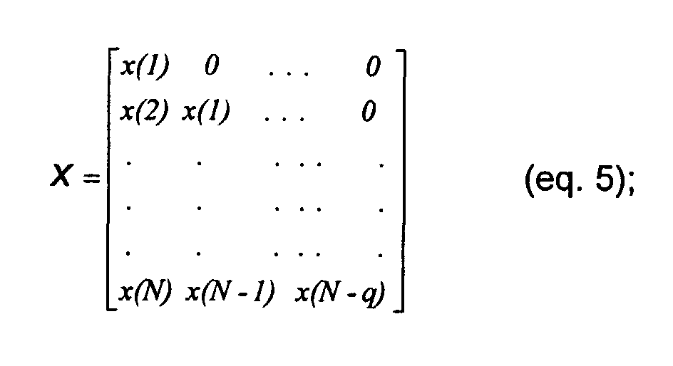
- the q + 1 of these frames are initially used as inputs, x , in equation 4, and the frames subsequently being used to provide outputs, y . That is, each output y(i) is equal to the previous input value x(i-1) .
- the value N is set equal to q + 1 in equation 5.
- equation 3 is used to obtain the first predicted output of the system.
- the first predicted output of the system is then used with the previous measured input data to obtain the second predicted output of the system.
- the outputs can be predicted in several manners, two of which are contemplated in the present embodiment.
- the first method described above is a special case of the second method, in which the value ⁇ is set equal to 0.
- the second method provides for filtering of the output values. In trials, a value of ⁇ equal to 0.35 was used with satisfactory results.
- exemplary control logic for carrying out the prediction and correction technique begins with the end of the previous exposure or examination, a radiographic exposure in the example, as indicated at reference numeral 104.
- Initial values are then sampled at the regular sampling intervals of the imaging system, as indicated at step 106. These initial values are stored as indicated at step 108, and the initial values are used in the modeling process outlined above.
- decaying values are then continuously sampled at regular sampling intervals throughout the interim period 94.
- Outputs are continuously predicted as indicated at step 112, based upon the initial values, and the subsequently collected decaying values.
- the control logic determines whether the modeling is complete. If the modeling is not complete, values are continuously sampled and outputs are predicted by returning to step 110. Once the modeling process is complete (ie. A model of the desired order is obtained) the system is characterized, as indicated at step 116, and as described above.
- the subsequent examination or exposure may begin, as indicated at step 118 in Fig. 5.
- the predicted retained image values may be calculated for the successive sampling intervals as indicated at step 120 and as described above.
- Step 120 also indicates that these values are used as corrections or offsets for the data acquired in the subsequent exposure.
- the predicted values and corrections may be calculated either previous to the subsequent exposure, during the subsequent exposure, or thereafter.
- the actual acquired values of the second exposure may be immediately corrected, or both these values and the correction values based upon the predicted decay may be stored for subsequent processing.
- the foregoing technique was employed for correcting for retained signals in fluoroscopic images after a radiographic exposure.
- a sampling rate of 30 frames per second was used, with maximum amplifier gain.
- Radiographic exposure levels of 80% and 200% of the level required to saturate the photodiodes were used.
- the sequence of fluoroscopic images, containing the decaying signal from the radiographic exposure, was stored for analysis. These measured data sets were then used as a benchmark against which the foregoing technique was analyzed by comparing the predicted values from the same conditions with the measured data. Prediction errors were noted within acceptable bounds.
Landscapes
- Physics & Mathematics (AREA)
- Health & Medical Sciences (AREA)
- Life Sciences & Earth Sciences (AREA)
- General Physics & Mathematics (AREA)
- High Energy & Nuclear Physics (AREA)
- Molecular Biology (AREA)
- Spectroscopy & Molecular Physics (AREA)
- Apparatus For Radiation Diagnosis (AREA)
- Image Input (AREA)
- Image Processing (AREA)
- Image Analysis (AREA)
Abstract
Description
Claims (10)
- A method for compensating for image retention in a digital imaging system, the method comprising the steps of:(a) acquiring data (106, 110) for a plurality of pixel regions (54) following a first examination sequence;(b) computing a predication model (112, 114) for decay of a retained image based upon the acquired data; and(c) correcting image data (120) for a second examination (118) based upon the prediction model.
- The method of claim 1, wherein the method is performed in a digital x-ray system (10), and wherein the first examination includes a radiographic exposure and the second examination includes a fluoroscopy exposure.
- The method of claim 1, comprising the further step of storing (112, 116) predicted decaying image values for each pixel region and for forward-going sampling intervals, and wherein step (c) includes accessing the decaying image values for correction of data of the second examination acquired at corresponding sampling intervals.
- A method for correcting fluoroscopic image data acquired following a radiographic image sequence, the method comprising the steps of:(a) performing a radiographic imaging sequence in which image data for a plurality of pixel regions of a digital detector is sampled;(b) acquiring retained image data for the pixel regions following termination of the radiographic imaging sequence;(c) applying the retained image data to a prediction model to predict decay of a retained image in the detector;(d) performing a fluoroscopic imaging sequence; and(e) correcting fluoroscopic image data sampled from the detector during step (d) based upon the decay predicted in step (c).
- The method of claim 4, wherein the decay of the retained image is predicted in step (c) for at least a portion of the sampling intervals of a the fluoroscopic imaging sequence performed in step (d).
- The method of claim 4, comprising the further step of storing predicted retained image decay values for forward-going sampling intervals, the forward-going sampling intervals corresponding at least partially to sampling intervals for the fluoroscopic imaging sequence of step (d).
- A digital x-ray imaging system, the system comprising:a radiation source (12);a radiation detector (22) for receiving radiation from the source and generating image data based upon the received radiation; anda signal processing circuit (28, 32) coupled to the detector for processing the image data, the signal processing circuit being configured to sample retained image data (106, 110) from the detector following a first examination sequence and during a period in which no radiation from the source impacts the detector, to predict decay (112) of a retained image in the detector based upon the retained image data, and to correct image data (120) for a second examination sequence based upon the predicted decay.
- The system of claim 7, wherein the first examination sequence is a radiographic examination wherein the radiation source (12) emits radiation at a first level, and the second examination sequence is a fluoroscopic examination wherein the radiation source (12) emits radiation at a second level lower than the first level.
- A computer program for correction of image data in a digital x-ray imaging system, the computer program comprising:a machine readable medium for storing programming code; andprogramming code stored on the machine readable medium, the programming code providing instructions for a signal processing circuit of an imaging system for analyzing sampled retained image data from an imaging detector acquired following a first examination sequence, predicting decay of a retained image based upon the retained image data, and generating correction values for compensating for the retained image in data acquired in a second examination sequence.
- The computer program of claim 9, wherein the programming code includes a prediction model for predicting forward-going retained image decay values based upon the retained image data.
Applications Claiming Priority (2)
| Application Number | Priority Date | Filing Date | Title |
|---|---|---|---|
| US475874 | 1999-12-30 | ||
| US09/475,874 US6353654B1 (en) | 1999-12-30 | 1999-12-30 | Method and apparatus for compensating for image retention in an amorphous silicon imaging detector |
Publications (2)
| Publication Number | Publication Date |
|---|---|
| EP1113293A2 true EP1113293A2 (en) | 2001-07-04 |
| EP1113293A3 EP1113293A3 (en) | 2002-09-11 |
Family
ID=23889522
Family Applications (1)
| Application Number | Title | Priority Date | Filing Date |
|---|---|---|---|
| EP00311612A Withdrawn EP1113293A3 (en) | 1999-12-30 | 2000-12-22 | Method and apparatus for compensating for image retention in an amorphous silicon imaging detector |
Country Status (3)
| Country | Link |
|---|---|
| US (1) | US6353654B1 (en) |
| EP (1) | EP1113293A3 (en) |
| JP (1) | JP2001243454A (en) |
Cited By (4)
| Publication number | Priority date | Publication date | Assignee | Title |
|---|---|---|---|---|
| FR2831013A1 (en) * | 2001-10-15 | 2003-04-18 | Gen Electric | METHOD AND SYSTEM FOR PROCESSING A FLUOROSCOPIC IMAGE |
| FR2854528A1 (en) * | 2003-05-02 | 2004-11-05 | Ge Med Sys Global Tech Co Llc | RADIOSCOPIC IMAGE PROCESSING METHOD AND APPARATUS |
| DE102005057667B3 (en) * | 2005-12-01 | 2007-02-01 | Siemens Ag | Method for correcting image from sequence of X-ray images e.g., for computer tomography, involves subtracting corrected image elements with dimensions exceeding specified threshold |
| WO2022161478A1 (en) * | 2021-01-28 | 2022-08-04 | Shanghai United Imaging Healthcare Co., Ltd. | System and method for pet data compensation |
Families Citing this family (14)
| Publication number | Priority date | Publication date | Assignee | Title |
|---|---|---|---|---|
| FI111759B (en) * | 2000-03-14 | 2003-09-15 | Planmed Oy | Arrangement with sensor and procedure for digital x-ray imaging |
| US6751289B2 (en) * | 2000-10-10 | 2004-06-15 | Kabushiki Kaisha Toshiba | X-ray diagnostic apparatus |
| US6535576B2 (en) * | 2000-12-29 | 2003-03-18 | Ge Medical Systems Global Technology Company, Llc | Enhanced digital detector and system and method incorporating same |
| US6895077B2 (en) * | 2001-11-21 | 2005-05-17 | University Of Massachusetts Medical Center | System and method for x-ray fluoroscopic imaging |
| EP1573896A4 (en) * | 2002-10-16 | 2008-08-20 | Varian Med Sys Tech Inc | METHOD AND DEVICE FOR CORRECTING SIGNAL EXCESSES IN IMAGING DEVICE |
| US7473903B2 (en) * | 2003-02-12 | 2009-01-06 | General Electric Company | Method and apparatus for deposited hermetic cover for digital X-ray panel |
| JP4178071B2 (en) * | 2003-04-23 | 2008-11-12 | 株式会社日立メディコ | X-ray diagnostic imaging equipment |
| US7005663B2 (en) * | 2003-08-22 | 2006-02-28 | Ge Medical Systems Global Technology Company, Llc | Sampling methods and systems that shorten readout time and reduce lag in amorphous silicon flat panel x-ray detectors |
| US7218705B2 (en) * | 2005-06-25 | 2007-05-15 | General Electric | Systems, methods and apparatus to offset correction of X-ray images |
| JP2009514636A (en) * | 2005-11-09 | 2009-04-09 | コーニンクレッカ フィリップス エレクトロニクス エヌ ヴィ | Method for reducing 3D ghost artifacts in X-ray detectors |
| US9629591B2 (en) * | 2011-01-21 | 2017-04-25 | General Electric Company | X-ray system and method with digital image acquisition |
| US8576986B2 (en) | 2011-01-21 | 2013-11-05 | General Electric Company | X-ray system and method for sampling image data |
| EP2665419B1 (en) * | 2011-01-21 | 2016-08-03 | General Electric Company | X-ray system and method with digital image acquisition |
| US8768035B2 (en) * | 2011-04-27 | 2014-07-01 | General Electric Company | X-ray system and method for processing image data |
Family Cites Families (4)
| Publication number | Priority date | Publication date | Assignee | Title |
|---|---|---|---|---|
| US4427999A (en) * | 1977-06-06 | 1984-01-24 | Coulter Systems Corporation | High speed imaging of electrophotographic film by fine beam scanning |
| US4468707A (en) * | 1977-06-06 | 1984-08-28 | Coulter Systems Corporation | High speed imaging of electrophotographic film by fine beam scanning |
| DE69429142T2 (en) * | 1993-09-03 | 2002-08-22 | Koninklijke Philips Electronics N.V., Eindhoven | X-ray image |
| DE69738105T2 (en) * | 1996-12-23 | 2008-05-29 | Koninklijke Philips Electronics N.V. | X-ray examination device with X-ray image sensor matrix and correction unit |
-
1999
- 1999-12-30 US US09/475,874 patent/US6353654B1/en not_active Expired - Lifetime
-
2000
- 2000-12-22 EP EP00311612A patent/EP1113293A3/en not_active Withdrawn
- 2000-12-28 JP JP2000399851A patent/JP2001243454A/en not_active Withdrawn
Cited By (6)
| Publication number | Priority date | Publication date | Assignee | Title |
|---|---|---|---|---|
| FR2831013A1 (en) * | 2001-10-15 | 2003-04-18 | Gen Electric | METHOD AND SYSTEM FOR PROCESSING A FLUOROSCOPIC IMAGE |
| FR2854528A1 (en) * | 2003-05-02 | 2004-11-05 | Ge Med Sys Global Tech Co Llc | RADIOSCOPIC IMAGE PROCESSING METHOD AND APPARATUS |
| US6920198B2 (en) | 2003-05-02 | 2005-07-19 | Ge Medical Systems Global Technology Company, Llc | Methods and apparatus for processing a fluoroscopic image |
| DE102005057667B3 (en) * | 2005-12-01 | 2007-02-01 | Siemens Ag | Method for correcting image from sequence of X-ray images e.g., for computer tomography, involves subtracting corrected image elements with dimensions exceeding specified threshold |
| US7579584B2 (en) | 2005-12-01 | 2009-08-25 | Siemens Aktiengesellschaft | Method for correction of an image from a series of images acquired with an x-ray detector |
| WO2022161478A1 (en) * | 2021-01-28 | 2022-08-04 | Shanghai United Imaging Healthcare Co., Ltd. | System and method for pet data compensation |
Also Published As
| Publication number | Publication date |
|---|---|
| EP1113293A3 (en) | 2002-09-11 |
| US6353654B1 (en) | 2002-03-05 |
| JP2001243454A (en) | 2001-09-07 |
Similar Documents
| Publication | Publication Date | Title |
|---|---|---|
| US6353654B1 (en) | Method and apparatus for compensating for image retention in an amorphous silicon imaging detector | |
| US7313224B1 (en) | Wireless integrated automatic exposure control module | |
| US7512214B2 (en) | Radiography apparatus, radiography system, and control method thereof | |
| US6920198B2 (en) | Methods and apparatus for processing a fluoroscopic image | |
| US20050184243A1 (en) | Radiological imaging apparatus and method | |
| US20120230469A1 (en) | Radiation imaging apparatus and method for controlling the same | |
| EP0833505A2 (en) | Fast scan reset for a large area X-ray detector | |
| WO2003057039A1 (en) | X-ray diagnosis apparatus | |
| CN101282427A (en) | Imaging device, imaging system, control method thereof, and storage medium for program thereof | |
| US6944267B2 (en) | X-ray image diagnostic device, and x-ray image data correcting method | |
| US6498831B2 (en) | Panel detector pixel replacement method and apparatus | |
| US7218705B2 (en) | Systems, methods and apparatus to offset correction of X-ray images | |
| US6393097B1 (en) | Digital detector method for dual energy imaging | |
| JP2001099944A (en) | Noise reduction method for radiation detector, radiation detector, and radiodiagnostic device | |
| US7139364B2 (en) | X-ray-tomographic imaging apparatus, X-ray-tomographic imaging method, and program | |
| US7065177B2 (en) | Method and apparatus for correcting a retained image artifact | |
| JP2002369084A (en) | Imaging apparatus and method, radiation imaging apparatus and method, and storage medium and program | |
| US6243440B1 (en) | Radiographic apparatus | |
| US7138636B2 (en) | Systems, methods and apparatus to calibrate a solid state X-ray detector | |
| US7122802B2 (en) | Method and apparatus for increasing the data acquisition rate in a digital detector | |
| US7792251B2 (en) | Method for the correction of lag charge in a flat-panel X-ray detector | |
| EP1186910B1 (en) | Means for measuring the offset induced by photo-conductive fets in a solid state x-ray detector | |
| US6721441B1 (en) | Extended dynamic range system for digital X-ray imaging detectors | |
| US8107709B2 (en) | Apparatus and method for processing radiation image | |
| JP4907232B2 (en) | X-ray equipment |
Legal Events
| Date | Code | Title | Description |
|---|---|---|---|
| PUAI | Public reference made under article 153(3) epc to a published international application that has entered the european phase |
Free format text: ORIGINAL CODE: 0009012 |
|
| AK | Designated contracting states |
Kind code of ref document: A2 Designated state(s): AT BE CH CY DE DK ES FI FR GB GR IE IT LI LU MC NL PT SE TR |
|
| AX | Request for extension of the european patent |
Free format text: AL;LT;LV;MK;RO;SI |
|
| PUAL | Search report despatched |
Free format text: ORIGINAL CODE: 0009013 |
|
| RIC1 | Information provided on ipc code assigned before grant |
Free format text: 7G 01T 1/29 A, 7G 01T 1/00 B |
|
| AK | Designated contracting states |
Kind code of ref document: A3 Designated state(s): AT BE CH CY DE DK ES FI FR GB GR IE IT LI LU MC NL PT SE TR |
|
| AX | Request for extension of the european patent |
Free format text: AL;LT;LV;MK;RO;SI |
|
| 17P | Request for examination filed |
Effective date: 20030311 |
|
| AKX | Designation fees paid |
Designated state(s): DE FR NL |
|
| 17Q | First examination report despatched |
Effective date: 20040621 |
|
| STAA | Information on the status of an ep patent application or granted ep patent |
Free format text: STATUS: THE APPLICATION IS DEEMED TO BE WITHDRAWN |
|
| 18D | Application deemed to be withdrawn |
Effective date: 20041103 |