EP1113206A2 - Shutoff valve lockout device - Google Patents
Shutoff valve lockout device Download PDFInfo
- Publication number
- EP1113206A2 EP1113206A2 EP00308847A EP00308847A EP1113206A2 EP 1113206 A2 EP1113206 A2 EP 1113206A2 EP 00308847 A EP00308847 A EP 00308847A EP 00308847 A EP00308847 A EP 00308847A EP 1113206 A2 EP1113206 A2 EP 1113206A2
- Authority
- EP
- European Patent Office
- Prior art keywords
- housing
- cover
- lockout device
- valve handles
- valve
- Prior art date
- Legal status (The legal status is an assumption and is not a legal conclusion. Google has not performed a legal analysis and makes no representation as to the accuracy of the status listed.)
- Withdrawn
Links
- 230000007246 mechanism Effects 0.000 claims description 16
- 239000007789 gas Substances 0.000 description 18
- 238000000034 method Methods 0.000 description 8
- 239000000463 material Substances 0.000 description 5
- 229910000831 Steel Inorganic materials 0.000 description 4
- 238000013461 design Methods 0.000 description 4
- 230000008569 process Effects 0.000 description 4
- 239000010959 steel Substances 0.000 description 4
- 229910052751 metal Inorganic materials 0.000 description 3
- 239000002184 metal Substances 0.000 description 3
- IJGRMHOSHXDMSA-UHFFFAOYSA-N Atomic nitrogen Chemical compound N#N IJGRMHOSHXDMSA-UHFFFAOYSA-N 0.000 description 2
- 238000013459 approach Methods 0.000 description 2
- 238000005452 bending Methods 0.000 description 2
- 230000013011 mating Effects 0.000 description 2
- 239000004033 plastic Substances 0.000 description 2
- 229920003023 plastic Polymers 0.000 description 2
- 230000000452 restraining effect Effects 0.000 description 2
- 230000000007 visual effect Effects 0.000 description 2
- 235000012431 wafers Nutrition 0.000 description 2
- UFHFLCQGNIYNRP-UHFFFAOYSA-N Hydrogen Chemical compound [H][H] UFHFLCQGNIYNRP-UHFFFAOYSA-N 0.000 description 1
- XUIMIQQOPSSXEZ-UHFFFAOYSA-N Silicon Chemical compound [Si] XUIMIQQOPSSXEZ-UHFFFAOYSA-N 0.000 description 1
- 229910052782 aluminium Inorganic materials 0.000 description 1
- XAGFODPZIPBFFR-UHFFFAOYSA-N aluminium Chemical compound [Al] XAGFODPZIPBFFR-UHFFFAOYSA-N 0.000 description 1
- 230000000712 assembly Effects 0.000 description 1
- 238000000429 assembly Methods 0.000 description 1
- 230000008859 change Effects 0.000 description 1
- 238000012790 confirmation Methods 0.000 description 1
- 239000011888 foil Substances 0.000 description 1
- 239000011521 glass Substances 0.000 description 1
- 239000001257 hydrogen Substances 0.000 description 1
- 229910052739 hydrogen Inorganic materials 0.000 description 1
- 238000009434 installation Methods 0.000 description 1
- 230000004048 modification Effects 0.000 description 1
- 238000012986 modification Methods 0.000 description 1
- 229910052757 nitrogen Inorganic materials 0.000 description 1
- 239000002990 reinforced plastic Substances 0.000 description 1
- 238000007789 sealing Methods 0.000 description 1
- 239000004065 semiconductor Substances 0.000 description 1
- 229910052710 silicon Inorganic materials 0.000 description 1
- 239000010703 silicon Substances 0.000 description 1
- 229910001220 stainless steel Inorganic materials 0.000 description 1
- 239000010935 stainless steel Substances 0.000 description 1
- 229920001169 thermoplastic Polymers 0.000 description 1
- 229920001187 thermosetting polymer Polymers 0.000 description 1
- 239000004416 thermosoftening plastic Substances 0.000 description 1
Images




Classifications
-
- F—MECHANICAL ENGINEERING; LIGHTING; HEATING; WEAPONS; BLASTING
- F16—ENGINEERING ELEMENTS AND UNITS; GENERAL MEASURES FOR PRODUCING AND MAINTAINING EFFECTIVE FUNCTIONING OF MACHINES OR INSTALLATIONS; THERMAL INSULATION IN GENERAL
- F16K—VALVES; TAPS; COCKS; ACTUATING-FLOATS; DEVICES FOR VENTING OR AERATING
- F16K35/00—Means to prevent accidental or unauthorised actuation
- F16K35/10—Means to prevent accidental or unauthorised actuation with locking caps or locking bars
-
- F—MECHANICAL ENGINEERING; LIGHTING; HEATING; WEAPONS; BLASTING
- F16—ENGINEERING ELEMENTS AND UNITS; GENERAL MEASURES FOR PRODUCING AND MAINTAINING EFFECTIVE FUNCTIONING OF MACHINES OR INSTALLATIONS; THERMAL INSULATION IN GENERAL
- F16K—VALVES; TAPS; COCKS; ACTUATING-FLOATS; DEVICES FOR VENTING OR AERATING
- F16K51/00—Other details not peculiar to particular types of valves or cut-off apparatus
Definitions
- the present invention relates to the field of shut off valve lockout devices for mechanical flow valves, and more specifically to a method and structure for mechanically restraining the valve actuators from movement or for denying access to the valve actuators which control flow through the valves.
- locking features may be in the form of a pin, bolt, tab, flange, ring, or collar.
- the device is completed with the addition of a locking mechanism to prevent removal of the locking feature.
- a typical approach might be to add features to the valve; one to the moveable portion and a second feature to the nonmoveable portion of the valve, the features each having a hole (slot or some similar feature) through which a locking mechanism can be engaged thus restricting movement of the two features relative to each other, thereby locking the valve in a position.
- valve lockout devices To install, these valve lockout devices generally require, in varying degrees, some disassembly or modification of each valve to be locked out. These devices require a separate lockout device for each valve and a separate locking mechanism for each valve for the lockout to function. With today's more complex equipment, there is a need for a simple way to quickly and reliably lockout one or a series of valves easily with a device having minimal intrusion to the valve assemblies.
- a housing is formed of a shape to fit over and around one or a plurality of valve handles.
- the housing surface has slots in which are placed valve handle stems.
- a cover is shaped to mate with the housing. The cover and housing form an assembly and when the assembly is properly installed on a set of valve handles, the lockout device cannot be removed from the valve handles.
- the lockout device functions by denying access to the valve handles and the valves are effectively locked in a position.
- a novel device lockout structure for preventing actuation of a plurality of valves is described.
- numerous details are set forth such as specific materials in order to provide a thorough understanding of the present invention.
- well-known valve designs and functions have not been set forth in detail so that the present invention is clearly described.
- the present invention is a novel device structure and method for preventing actuation of flow control valves.
- a lockout device functions by placing a structure around a set of valve handles or actuators to be locked out.
- An actuator is a device which moves to block or allow flow through a valve and for the purposes of this invention, a valve handle is used as illustration of such an actuator. Once in place, the lockout device physically denies access to the valve handles, and thus the valve flow settings cannot be changed.
- a gas flow control system such as used in a 300mm Epi mainframe by Applied Materials in Sunnyvale, CA is shown in Figures 1 and 2. Such a system is used to control various gases flowing into a process chamber that will fabricate semiconductor wafers.
- the 300mm Epi system gas flow control system is comprised of a main gas platter that provides the means for delivery and control of hydrogen and nitrogen to the system.
- a process module gas platter provides the means for delivery and control of silicon source and etch gases.
- filters, mass flow controllers, and regulators In line to the gas flow are filters, mass flow controllers, and regulators all connected by steel tubing and attached to a mainframe for structural support. Both the process module gas platter and the main gas platter have shut-off valves 180 which are manually operated by valve handles 105.
- valve handles 105 are linearly positioned on a panel 170 located at a mainframe 165 edge. Gas lines run from the gas panel down the mainframe 165 and are routed to a gas manifold at the process chamber.
- the 300mm Epi system gas flow control system provides the necessary environment of controlled pressure and gas flows to ensure uniformity among wafers and as such, this gas flow control system provides a good application for the present invention.
- Lockout device 100 comprises a housing 102 and a cover 110 which constitute a housing/cover assembly 102/110, the housing/cover assembly 102/110 being pivotally attached 104/107 at one end with a pin.
- the housing/cover assembly 102/110 is pivoted closed with the valve handles 105 contained within the housing/cover assembly 102/110.
- the housing/cover assembly 102/110 has a feature that snaps shut to provide confirmation that the housing/cover assembly 102/110 is properly closed. Once the housing/cover assembly 102/110 is installed on the valve handles 105, access to the valve handles 105 is effectively denied.
- valve handles 105 have a long 121 and a short 122 dimension such as an oval shape. If any of the valve handles 105 remain in the on position, the on positioned handles 105 will mechanically interfere with installation of the lockout device 100. With such interference, the housing/cover assembly 102/110 will not close properly. When all the valve handles are in the off position, as shown in figure 5b, the housing/cover assembly 102/110 can close and a tab snap fit-interference feature will engage.
- the housing/cover assembly 102/110 is pivotally attached at one end to allow movement, in one plane, of the housing 102 relative to the cover 110.
- a tab 125 on the cover 110 At the other end of the assembly is placed a tab 125 on the cover 110 and a tab 130 on the housing 102.
- the two tabs 125, 130 are located such that, upon closing the cover 110 to the housing 102 for lockout operation, both tabs 125, 130 are adjacent to each other.
- the housing tab 130 has a lip 135 that when mated with the cover tab 125 for lockout operation, protrudes over the free end of the cover tab 125 thus providing a clear visual indication of proper lockout.
- the housing tab lip 135 is designed to slightly interfere with the mating cover tab 125 during closure of the housing/cover assembly 102/110 so as to provide a "snap-fit" when the cover 110 and housing 100 are closed and functioning properly. To accomplish this snap-fit, a slight bending of the tabs 125, 135 will be required during the closing operation of the housing/cover assembly 102/110 until the lip 135 clears the end of the tab 125 and snaps back into place over the end of the tab 125.
- the open end of the housing slots 140 provide access for the valve handles 105 to the inside of the housing 102.
- the housing 102 and cover are 110 formed by bending metal sheet stock having a thickness of 0.09" which will provide the necessary integrity of the lockout device and still allow the back surface of the housing 102 to fit between the valve handles 105 and the panel surface 170 (figures 1 & 2).
- the slot widths are 0.718" which is sufficient to fit around a series of valve handle stems 106.
- the slot width dimension is less than the valve handle dimension opposing it such that the valve handles 105 cannot pass through the slots.
- the housing 102 can be fabricated with a height of 1.50", a depth of 0.86", and a length of 15.94" which is sufficient to encompass a set often valve handles 105 to be locked out of the gas flow control system.
- the housing 102 has a set often slots 140 that are open at one end and have a full radius at the other end. In the preferred embodiment, the slots 140 are appropriately spaced with 1.60" centers and a depth from the housing edge to the slot radius center point of 0. 75" so as to mate with up to ten valve handles 105 and valve stems 106.
- the housing 102 has a set of holes 104 for pivotally attaching to the cover 110. As shown in figure 7, the cover has a set of holes 107 for pivotally attaching to the housing. The 104/107 holes, when aligned, are pinned (not shown) to complete the pivot feature.
- the cover 110 has edges 109 that will be positioned outside of the housing 102 when the housing/cover assembly 102/110 is closed.
- figure 8 provides, with the aid of a cutout view 112 in the housing 102, an illustration of a properly closed condition wherein the housing/cover assembly 102/110 is closed around the valve handles 105, the housing lip 135 is snapped in place over the cover tab 125, the valve handles 105 are all set in the off position, the lockout device 100 cannot be removed from the valve handles 105 without unsnapping or releasing the tabs 125/130, and access to the valve handles 105 is denied.
- the lockout device 100 when locking out valves 180, the lockout device 100 is positioned to surround or enclose the valve handles 105 with a cage like structure (housing/cover assembly 102/110) to deny access to the valve handles.
- the lockout device 100 does not require a rigid, fixed, or hard link to any part of the valve actuation mechanism such as the valve handles 105 or valve stems 106 in order to function.
- a lockout device is designed to lockout a single valve 180 (figures 1 & 2).
- a single valve lockout device is designed to restrict access to one valve handle 105.
- This lockout device could use the "contour" shape design or the "deny access” design.
- a problem is that the lockout device could turn freely thus allowing the valve handle to be turned. To stop this movement ,when the lockout device is installed, the lockout device may have to be restrained from turning. Such restraint could be accomplished by placing a second lockout device next to the first lockout device. In this way, a side of each device, adjacent to the other device, restricts movement of each lockout device or, alternatively, a feature such as a slot or tab on the valve support structure 160, 165, or 170 could function to restrict lockout device rotation.
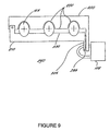
- FIG. 9 Another embodiment of the present invention is shown in figure 9, wherein a housing 200 and a cover 210 are fixedly attached by a pivot at one end providing a housing/cover assembly 200/210.
- the housing/cover assembly 200/210 functions by pivoting the housing 200 relative to the cover 210 so as to enclose a set of valve handles 105 to be locked out within the housing/cover assembly 200/210.
- the housing 200 provides a shape having a contour 220 that matches or follows those of the valve handles 105 and a spacing between the valve handles 105 to be enclosed.
- the cover 210 provides a surface 230 that is positioned behind the valve handles 105 when the housing/cover 200/210 is installed.
- the housing contour 220 rests against the valve handles 105, and the cover surface 230 is behind the valve handles 105, and the tab snap-fit feature is in operation.
- behind refers to the side of the valve handle 105 that receives the spindle 106 (as previously shown is figure 4).
- the lockout device 240 provides a mechanical restraint to the valve handles 105 such that the valve handles 105 cannot be moved and the lockout device 240 cannot be removed while in the properly closed position.
- the contour 220 would be shaped to fit valve handles 105 that were all in a closed position. However, it should be appreciated that such a contour 220 could be designed to accommodate any combination of on, partial on, or off valve handle positions 105.
- a housing 250 is integral or fixedly attached to a panel 260 on which is situated the valve handles 105, and/or the valve stems 106 (as previously shown in figure 4).
- the valve handles 105 are located within the housing 250.
- the housing 250 provides an open face for access to the valve handles 105 during normal operation of the valves 180.
- a method of sealing off this open face is provided with the addition of a clear cover 280 that mates to the housing 250. Such a mating is accomplished by sliding the cover 280 into grooves 270 which are positioned on the inside of the housing 250. In this manner, the lockout device will deny physical access to the valve handles 105 yet provide visual access to confirm the position of the valve handles 105 locked out.
- a single or a series of valves handles can be locked out such that the valve flow settings cannot be changed. It is possible with the present invention to lock out a series of valve handles aligned in a row. It is possible for the present invention to be designed to lockout a single valve handle. It is also possible for the present invention to be designed to lockout a plurality of valve handles which are not in a row but are staggered or placed in some non-symmetric pattern. It is also a feature of the present invention to make the lockout device integral to a structure providing support for the valves, the valve handles, or the valve stems. It is also possible to lock out a plurality of valves through the use of a plurality of lockout devices that can be added or "stacked" until the desired coverage of locked out valves is accomplished.
- the first embodiment was designed to meet a safety purpose that the lockout device only function when all valves locked out were in a closed position and that the lockout device not block or lockout access to any valves which were open. In another embodiment this design criterion may not be observed, in that lockout for any combination of a number of valves open and a number of valves closed may be desired.
- the housings are formed from steel and then painted, the covers are also formed from steel and painted with the exception of the integral housing embodiment where the cover would be made of a clear material.
- the invention may be constructed of a variety of materials sufficient to maintain the desired integrity of the lockout device.
- the housing and the cover could be constructed from materials including; cast, woven, or a formed metal such as steel, stainless steel, and aluminum or from a range of plastics including both thermosets and thermoplastics and further including reinforced plastics and glass.
- the housing/cover assembly may be locked in place providing further assurance that the lockout device cannot be removed from the valve handles 105 locked out.
- the locking mechanism could be a lock 108 (figures 3 & 9) that could attach through holes in both the housing and the cover tabs (such as shown in tabs 130/125 of figure 3).
- the locking mechanism could include other forms of restraining devices such as; wires, malleable metal foil, plastic loops or ties, tape, and the like that attaches to, through, or interferes with the housing and/or cover movement or a feature thereon, thereby locking the housing/cover assembly in place around the valves to be locked out.
- a "properly closed position" for the lockout device refers to the intended position of the housing, the cover, and the valve handles to be locked out, when the lockout device is installed to function as designed.
Landscapes
- Engineering & Computer Science (AREA)
- General Engineering & Computer Science (AREA)
- Mechanical Engineering (AREA)
- Preventing Unauthorised Actuation Of Valves (AREA)
- Fluid-Pressure Circuits (AREA)
- Valve Housings (AREA)
Abstract
Description
- The present invention relates to the field of shut off valve lockout devices for mechanical flow valves, and more specifically to a method and structure for mechanically restraining the valve actuators from movement or for denying access to the valve actuators which control flow through the valves.
- Today's safety environment routinely requires a means to lockout the operating mechanism of a valve so that the flow setting of the valve cannot easily be changed. Currently, there are a variety of devices in the market place which attach to the valve and provide a means to lockout a single valve. What is available is a device that must be attached to the valve in a way that usually requires some disassembly of the valve. These devices function by preventing a change in the valve setting of on or off (flow or no flow, open or closed) through the addition of a locking feature which fixes, through a physical connection such as a mechanical link, the moveable to the nonmoveable portion of the valve thereby preventing relative movement. These locking features may be in the form of a pin, bolt, tab, flange, ring, or collar. The device is completed with the addition of a locking mechanism to prevent removal of the locking feature. A typical approach might be to add features to the valve; one to the moveable portion and a second feature to the nonmoveable portion of the valve, the features each having a hole (slot or some similar feature) through which a locking mechanism can be engaged thus restricting movement of the two features relative to each other, thereby locking the valve in a position.
- To install, these valve lockout devices generally require, in varying degrees, some disassembly or modification of each valve to be locked out. These devices require a separate lockout device for each valve and a separate locking mechanism for each valve for the lockout to function. With today's more complex equipment, there is a need for a simple way to quickly and reliably lockout one or a series of valves easily with a device having minimal intrusion to the valve assemblies.
- In the present invention is described a lockout device having a novel approach to restricting operation of one or more valves and its method of use. According to the present invention, a housing is formed of a shape to fit over and around one or a plurality of valve handles. The housing surface has slots in which are placed valve handle stems. A cover is shaped to mate with the housing. The cover and housing form an assembly and when the assembly is properly installed on a set of valve handles, the lockout device cannot be removed from the valve handles. The lockout device functions by denying access to the valve handles and the valves are effectively locked in a position.
- The following is a description of some specific embodiments of the invention, reference being made to the accompanying drawings, in which:
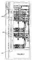
- Figure 1 is a three-dimensional illustration of a gas flow control system having a plurality of valves and valve handles.
- Figure 2 is a two-dimensional view of figure 1.
- Figure 3 is a three-dimensional illustration of the present invention.
- Figure 4 is a three-dimensional illustration of a valve handle installed within a housing.
- Figure 5a is an illustration of a housing/cover assembly which cannot properly close due to interference from some valve handles with settings in the on position.
- Figure 5b is an illustration of a housing/cover assembly which is properly closed due to non-interference from valve handles all set in the off position.
- Figure 6 is a three-dimensional wireframe illustration of a housing.
- Figure 7 is a three-dimensional wireframe illustration of a cover.
- Figure 8 is an illustration of the present invention installed onto a set often valve handles.
- Figure 9 is an illustration of a lockout device which restrains the valve handles with a housing having a contour that matches valve handle shape and spacing.
- Figure 10 is a three-dimensional illustration of a gas flow control system which has the housing integral to a panel and within which are positioned the valve handles.
-
- A novel device lockout structure for preventing actuation of a plurality of valves is described. In the following description numerous details are set forth such as specific materials in order to provide a thorough understanding of the present invention. In other instances well-known valve designs and functions have not been set forth in detail so that the present invention is clearly described.
- The present invention is a novel device structure and method for preventing actuation of flow control valves. A lockout device functions by placing a structure around a set of valve handles or actuators to be locked out. An actuator is a device which moves to block or allow flow through a valve and for the purposes of this invention, a valve handle is used as illustration of such an actuator. Once in place, the lockout device physically denies access to the valve handles, and thus the valve flow settings cannot be changed.
- A gas flow control system such as used in a 300mm Epi mainframe by Applied Materials in Sunnyvale, CA is shown in Figures 1 and 2. Such a system is used to control various gases flowing into a process chamber that will fabricate semiconductor wafers. The 300mm Epi system gas flow control system is comprised of a main gas platter that provides the means for delivery and control of hydrogen and nitrogen to the system. A process module gas platter provides the means for delivery and control of silicon source and etch gases. In line to the gas flow are filters, mass flow controllers, and regulators all connected by steel tubing and attached to a mainframe for structural support. Both the process module gas platter and the main gas platter have shut-off
valves 180 which are manually operated byvalve handles 105. Thesevalve handles 105 are linearly positioned on apanel 170 located at amainframe 165 edge. Gas lines run from the gas panel down themainframe 165 and are routed to a gas manifold at the process chamber. The 300mm Epi system gas flow control system provides the necessary environment of controlled pressure and gas flows to ensure uniformity among wafers and as such, this gas flow control system provides a good application for the present invention. - Shown in Figure 3 is a first embodiment of a
lockout device 100 of the present invention.Lockout device 100 comprises ahousing 102 and acover 110 which constitute a housing/cover assembly 102/110, the housing/cover assembly 102/110 being pivotally attached 104/107 at one end with a pin. When the valve handles 105 to be locked out are in a closed position, the housing/cover assembly 102/110 is pivoted closed with thevalve handles 105 contained within the housing/cover assembly 102/110. The housing/cover assembly 102/110 has a feature that snaps shut to provide confirmation that the housing/cover assembly 102/110 is properly closed. Once the housing/cover assembly 102/110 is installed on thevalve handles 105, access to thevalve handles 105 is effectively denied. - As shown in figure 4, to install the
lockout device 100,slots 140 in the housing are inserted around thevalve stems 106 of the closedvalves 180 with thevalve handles 105 positioned inside thehousing 102. Referring now to figure 5a, it can be seen that thevalve handles 105 have a long 121 and a short 122 dimension such as an oval shape. If any of thevalve handles 105 remain in the on position, the on positionedhandles 105 will mechanically interfere with installation of thelockout device 100. With such interference, the housing/cover assembly 102/110 will not close properly. When all the valve handles are in the off position, as shown in figure 5b, the housing/cover assembly 102/110 can close and a tab snap fit-interference feature will engage. - Shown in figures 5a & b, the housing/
cover assembly 102/110 is pivotally attached at one end to allow movement, in one plane, of thehousing 102 relative to thecover 110. At the other end of the assembly is placed atab 125 on thecover 110 and atab 130 on thehousing 102. The twotabs cover 110 to thehousing 102 for lockout operation, bothtabs housing tab 130 has alip 135 that when mated with thecover tab 125 for lockout operation, protrudes over the free end of thecover tab 125 thus providing a clear visual indication of proper lockout. Thehousing tab lip 135 is designed to slightly interfere with themating cover tab 125 during closure of the housing/cover assembly 102/110 so as to provide a "snap-fit" when thecover 110 andhousing 100 are closed and functioning properly. To accomplish this snap-fit, a slight bending of thetabs cover assembly 102/110 until thelip 135 clears the end of thetab 125 and snaps back into place over the end of thetab 125. - Returning to figure 4, when installing the lockout device, the open end of the
housing slots 140 provide access for thevalve handles 105 to the inside of thehousing 102. Thehousing 102 and cover are 110 formed by bending metal sheet stock having a thickness of 0.09" which will provide the necessary integrity of the lockout device and still allow the back surface of thehousing 102 to fit between thevalve handles 105 and the panel surface 170 (figures 1 & 2). The slot widths are 0.718" which is sufficient to fit around a series ofvalve handle stems 106. The slot width dimension is less than the valve handle dimension opposing it such that thevalve handles 105 cannot pass through the slots. - Turning now to figure 6, the
housing 102 can be fabricated with a height of 1.50", a depth of 0.86", and a length of 15.94" which is sufficient to encompass a set often valve handles 105 to be locked out of the gas flow control system. Thehousing 102 has a set oftenslots 140 that are open at one end and have a full radius at the other end. In the preferred embodiment, theslots 140 are appropriately spaced with 1.60" centers and a depth from the housing edge to the slot radius center point of 0. 75" so as to mate with up to ten valve handles 105 and valve stems 106. Thehousing 102 has a set ofholes 104 for pivotally attaching to thecover 110. As shown in figure 7, the cover has a set ofholes 107 for pivotally attaching to the housing. The 104/107 holes, when aligned, are pinned (not shown) to complete the pivot feature. Thecover 110 hasedges 109 that will be positioned outside of thehousing 102 when the housing/cover assembly 102/110 is closed. - For this embodiment, figure 8 provides, with the aid of a
cutout view 112 in thehousing 102, an illustration of a properly closed condition wherein the housing/cover assembly 102/110 is closed around the valve handles 105, thehousing lip 135 is snapped in place over thecover tab 125, the valve handles 105 are all set in the off position, thelockout device 100 cannot be removed from the valve handles 105 without unsnapping or releasing thetabs 125/130, and access to the valve handles 105 is denied. - For this embodiment, when locking out
valves 180, thelockout device 100 is positioned to surround or enclose the valve handles 105 with a cage like structure (housing/cover assembly 102/110) to deny access to the valve handles. Thelockout device 100 does not require a rigid, fixed, or hard link to any part of the valve actuation mechanism such as the valve handles 105 or valve stems 106 in order to function. - In another embodiment, a lockout device is designed to lockout a single valve 180 (figures 1 & 2). In this embodiment, a single valve lockout device is designed to restrict access to one
valve handle 105. This lockout device could use the "contour" shape design or the "deny access" design. A problem is that the lockout device could turn freely thus allowing the valve handle to be turned. To stop this movement ,when the lockout device is installed, the lockout device may have to be restrained from turning. Such restraint could be accomplished by placing a second lockout device next to the first lockout device. In this way, a side of each device, adjacent to the other device, restricts movement of each lockout device or, alternatively, a feature such as a slot or tab on thevalve support structure - Another embodiment of the present invention is shown in figure 9, wherein a
housing 200 and acover 210 are fixedly attached by a pivot at one end providing a housing/cover assembly 200/210. The housing/cover assembly 200/210 functions by pivoting thehousing 200 relative to thecover 210 so as to enclose a set of valve handles 105 to be locked out within the housing/cover assembly 200/210. Thehousing 200 provides a shape having acontour 220 that matches or follows those of the valve handles 105 and a spacing between the valve handles 105 to be enclosed. Thecover 210 provides asurface 230 that is positioned behind the valve handles 105 when the housing/cover 200/210 is installed. When thehousing 200 and cover 210 of this embodiment are in a properly closed position, thehousing contour 220 rests against the valve handles 105, and thecover surface 230 is behind the valve handles 105, and the tab snap-fit feature is in operation. For this embodiment, behind refers to the side of the valve handle 105 that receives the spindle 106 (as previously shown is figure 4). In this manner thelockout device 240 provides a mechanical restraint to the valve handles 105 such that the valve handles 105 cannot be moved and thelockout device 240 cannot be removed while in the properly closed position. It would be expected, but not required, that thecontour 220 would be shaped to fit valve handles 105 that were all in a closed position. However, it should be appreciated that such acontour 220 could be designed to accommodate any combination of on, partial on, or off valve handle positions 105. - In yet another embodiment as shown in figure 10, a
housing 250 is integral or fixedly attached to apanel 260 on which is situated the valve handles 105, and/or the valve stems 106 (as previously shown in figure 4). The valve handles 105 are located within thehousing 250. Thehousing 250 provides an open face for access to the valve handles 105 during normal operation of thevalves 180. A method of sealing off this open face is provided with the addition of aclear cover 280 that mates to thehousing 250. Such a mating is accomplished by sliding thecover 280 intogrooves 270 which are positioned on the inside of thehousing 250. In this manner, the lockout device will deny physical access to the valve handles 105 yet provide visual access to confirm the position of the valve handles 105 locked out. - Using a lockout device of the present invention, a single or a series of valves handles, can be locked out such that the valve flow settings cannot be changed. It is possible with the present invention to lock out a series of valve handles aligned in a row. It is possible for the present invention to be designed to lockout a single valve handle. It is also possible for the present invention to be designed to lockout a plurality of valve handles which are not in a row but are staggered or placed in some non-symmetric pattern. It is also a feature of the present invention to make the lockout device integral to a structure providing support for the valves, the valve handles, or the valve stems. It is also possible to lock out a plurality of valves through the use of a plurality of lockout devices that can be added or "stacked" until the desired coverage of locked out valves is accomplished.
- The first embodiment was designed to meet a safety purpose that the lockout device only function when all valves locked out were in a closed position and that the lockout device not block or lockout access to any valves which were open. In another embodiment this design criterion may not be observed, in that lockout for any combination of a number of valves open and a number of valves closed may be desired.
- For the above embodiments, the housings are formed from steel and then painted, the covers are also formed from steel and painted with the exception of the integral housing embodiment where the cover would be made of a clear material. However, the invention may be constructed of a variety of materials sufficient to maintain the desired integrity of the lockout device. The housing and the cover could be constructed from materials including; cast, woven, or a formed metal such as steel, stainless steel, and aluminum or from a range of plastics including both thermosets and thermoplastics and further including reinforced plastics and glass.
- For the above mentioned embodiments, after the housing/cover is closed, the housing/cover assembly may be locked in place providing further assurance that the lockout device cannot be removed from the valve handles 105 locked out. The locking mechanism could be a lock 108 (figures 3 & 9) that could attach through holes in both the housing and the cover tabs (such as shown in
tabs 130/125 of figure 3). Alternatively, the locking mechanism could include other forms of restraining devices such as; wires, malleable metal foil, plastic loops or ties, tape, and the like that attaches to, through, or interferes with the housing and/or cover movement or a feature thereon, thereby locking the housing/cover assembly in place around the valves to be locked out. - In the above described embodiments of the present invention there is referred to a "properly closed position" for the lockout device. This term refers to the intended position of the housing, the cover, and the valve handles to be locked out, when the lockout device is installed to function as designed.
Claims (20)
- A lockout device for valves, which comprises:a housing which fits over a plurality of valve handles; anda cover adapted to mate to the housing and create an assembly; such that when the cover mates with the housing, and is properly closed around the valve handles, the lockout device is constrained around the valve handles and access to the valve handles is denied.
- A lockout device as claimed in claim 1, wherein:
the cover and the housing are pivotally coupled at one end. - A lockout device as claimed in claim 1 or claim 2, wherein,
the cover and the housing are fixedly attached to a pivot at one end. - A lockout device as claimed in any of claims 1 to 3, further comprising:
a locking mechanism. - A lockout device as claimed in any of claims 1 to 4, further comprising:
a surface feature to visually determine the housing and the cover are properly engaged to deny access to the valve handles. - A lockout device as claimed in claim 5, further comprising:
the surface feature is markings. - A lockout device as claimed in claim 5, further comprising:
the surface feature is projections on the lockout device. - A lockout device as claimed in any of claims 5 to 7, in which:
the housing and the cover are designed to close sufficiently to allow the surface feature to line up indicating proper closure only when all the valve handles to be locked out are in an off position. - A lockout device as claimed in claim 8, in which:
the feature involves holes to receive a locking mechanism. - A lockout device as claimed in any of claims 1 to 9, further comprising:
a snap-fit feature to mechanically constrain housing movement relative to the cover. - A lockout device as claimed in claim 10, further comprising:
the housing and the cover are designed to close sufficiently to allow the snap-fit feature to engage only when all the valve handles to be locked out are in a particular position. - A lockout device as claimed in claim 11, in which:
the particular position is an off position. - A lockout device for valves, which comprises:a housing which fits over a plurality of valve handles;a cover adapted to fit to the housing, wherein the housing and the cover form an assembly and have a properly closed position; wherein when the assembly is properly closed, the valve handles are within the assembly, the valve handles are set to off, access to the valve handles is denied; anda locking mechanism operably interconnected between the housing and the cover to lock the housing and the cover in place around the valve handles such that the assembly cannot be removed from the valve handles.
- A lockout device as claimed in claim 13, further comprising:
the locking mechanism is structurally integral to the lockout device. - A lockout device as claimed in claim 13, further comprising:
the locking mechanism is structurally integral to a valve support structure. - A lockout device for valves, which comprises:a housing which fits over a plurality of valve handles;a cover adapted to mate with the housing; wherein the cover and the housing are pivotally attached at one end;the housing and the cover to have a properly closed position, wherein when the housing and the cover are properly closed around the valve handles, access to the valve handles is denied and the valve handles are in a closed position; anda lock mechanism operably interconnected between the housing and the cover for locking the housing and the cover in the properly closed position.
- A lockout device for valves, which comprises:a housing shaped to fit around a contour and a spacing of a plurality of valve handles;a cover adapted to mate to the housing such that when mated to the housing and properly closed, the plurality of valve handles are mechanically restrained in a position; anda feature on the system to receive a locking mechanism; such that when the cover and the housing are properly closed around the valve handles, and the locking mechanism is engaged, the lockout device cannot be removed from the valve handles.
- A lockout device as claimed in claim 17, wherein the valves are in an off position.
- A lockout device for one or more valves, which comprises:a housing fixedly attached to a support structure wherein are placed one or more valve handles; anda cover adapted to mate to the housing such that when mated to the housing in a properly closed position, the one or more valve handles are enclosed within the housing and cover and access to the valve handles is denied.
- A lockout device as claimed in claim 19 further comprising;
a lock mechanism operably interconnected between the housing and the cover for locking the housing and the cover in the properly closed position.
Applications Claiming Priority (2)
| Application Number | Priority Date | Filing Date | Title |
|---|---|---|---|
| US41408599A | 1999-10-06 | 1999-10-06 | |
| US414085 | 1999-10-06 |
Publications (2)
| Publication Number | Publication Date |
|---|---|
| EP1113206A2 true EP1113206A2 (en) | 2001-07-04 |
| EP1113206A3 EP1113206A3 (en) | 2002-07-31 |
Family
ID=23639895
Family Applications (1)
| Application Number | Title | Priority Date | Filing Date |
|---|---|---|---|
| EP00308847A Withdrawn EP1113206A3 (en) | 1999-10-06 | 2000-10-06 | Shutoff valve lockout device |
Country Status (4)
| Country | Link |
|---|---|
| EP (1) | EP1113206A3 (en) |
| JP (1) | JP2001248755A (en) |
| KR (1) | KR20010040020A (en) |
| TW (1) | TW479113B (en) |
Family Cites Families (3)
| Publication number | Priority date | Publication date | Assignee | Title |
|---|---|---|---|---|
| DE413334C (en) * | 1924-03-01 | 1925-05-09 | Josefine Roettgen | Gas valve shut-off device |
| US5687757A (en) * | 1995-05-04 | 1997-11-18 | Perry C. Heintz | Secure lock and spill preventer for fluid storage facility |
| US5806555A (en) * | 1997-01-31 | 1998-09-15 | Spears Manfacturing Co. | Locking device for valves |
-
2000
- 2000-10-05 TW TW089120818A patent/TW479113B/en not_active IP Right Cessation
- 2000-10-06 EP EP00308847A patent/EP1113206A3/en not_active Withdrawn
- 2000-10-06 KR KR1020000058842A patent/KR20010040020A/en not_active Withdrawn
- 2000-10-06 JP JP2000308016A patent/JP2001248755A/en not_active Withdrawn
Non-Patent Citations (1)
| Title |
|---|
| None |
Also Published As
| Publication number | Publication date |
|---|---|
| EP1113206A3 (en) | 2002-07-31 |
| KR20010040020A (en) | 2001-05-15 |
| TW479113B (en) | 2002-03-11 |
| JP2001248755A (en) | 2001-09-14 |
Similar Documents
| Publication | Publication Date | Title |
|---|---|---|
| EP0578770B1 (en) | Handle enclosure for valves | |
| US5579804A (en) | Tamper-proof handle extension for quarter turn valves | |
| CA2036892C (en) | Tamper-proof locking mechanism for quarter turn valves | |
| CA2926337C (en) | Valve handle lock | |
| US20070034259A1 (en) | Phosphorescent valve cover | |
| EP3175157B1 (en) | Tool-less valve actuator connector for a globe valve assembly | |
| CA1041315A (en) | Operating member locking device | |
| CA2033412C (en) | Lockout device for valves with lever handles | |
| EP2414715B1 (en) | Manual valve operators having a lockout device | |
| AU5868399A (en) | Safety device for opening a pressure cooker with lug-bayonet type closure | |
| EP3517814A1 (en) | Click-in pivot hinge anchor installation | |
| US8955540B2 (en) | Valve lock assembly | |
| EP3132166B1 (en) | Emergency shut-off valve | |
| EP2880344A1 (en) | Valve lockout device | |
| CA2061321C (en) | Apparatus for locking a valve actuating member | |
| KR20160143504A (en) | Valve with locking mechanism, and integrated valve | |
| EP3845787B1 (en) | Pull handle butterfly valve lockout device | |
| US8186186B1 (en) | Lock assembly | |
| US20150075648A1 (en) | Valve lockout device | |
| US20010032673A1 (en) | Ball valve locking device | |
| US11353128B2 (en) | Valve body apparatus for use with fluid valves | |
| US20200132215A1 (en) | Valve lockout | |
| JP7696147B1 (en) | Ball valve opening and closing handle fixing device | |
| KR20010040020A (en) | Shut off valve lockout device | |
| US6446666B1 (en) | Valve lock and adapter |
Legal Events
| Date | Code | Title | Description |
|---|---|---|---|
| PUAI | Public reference made under article 153(3) epc to a published international application that has entered the european phase |
Free format text: ORIGINAL CODE: 0009012 |
|
| AK | Designated contracting states |
Kind code of ref document: A2 Designated state(s): AT BE CH CY DE DK ES FI FR GB GR IE IT LI LU MC NL PT SE |
|
| AX | Request for extension of the european patent |
Free format text: AL;LT;LV;MK;RO;SI |
|
| PUAL | Search report despatched |
Free format text: ORIGINAL CODE: 0009013 |
|
| AK | Designated contracting states |
Kind code of ref document: A3 Designated state(s): AT BE CH CY DE DK ES FI FR GB GR IE IT LI LU MC NL PT SE |
|
| AX | Request for extension of the european patent |
Free format text: AL;LT;LV;MK;RO;SI |
|
| RIC1 | Information provided on ipc code assigned before grant |
Free format text: 7F 16K 35/10 A, 7F 16K 27/00 B |
|
| AKX | Designation fees paid | ||
| REG | Reference to a national code |
Ref country code: DE Ref legal event code: 8566 |
|
| STAA | Information on the status of an ep patent application or granted ep patent |
Free format text: STATUS: THE APPLICATION IS DEEMED TO BE WITHDRAWN |
|
| 18D | Application deemed to be withdrawn |
Effective date: 20030201 |