EP1113162A2 - Ducting for duel fan concept - Google Patents
Ducting for duel fan concept Download PDFInfo
- Publication number
- EP1113162A2 EP1113162A2 EP00311379A EP00311379A EP1113162A2 EP 1113162 A2 EP1113162 A2 EP 1113162A2 EP 00311379 A EP00311379 A EP 00311379A EP 00311379 A EP00311379 A EP 00311379A EP 1113162 A2 EP1113162 A2 EP 1113162A2
- Authority
- EP
- European Patent Office
- Prior art keywords
- primary
- ducts
- inlet
- discharge
- duct
- Prior art date
- Legal status (The legal status is an assumption and is not a legal conclusion. Google has not performed a legal analysis and makes no representation as to the accuracy of the status listed.)
- Granted
Links
Images


Classifications
-
- F—MECHANICAL ENGINEERING; LIGHTING; HEATING; WEAPONS; BLASTING
- F02—COMBUSTION ENGINES; HOT-GAS OR COMBUSTION-PRODUCT ENGINE PLANTS
- F02C—GAS-TURBINE PLANTS; AIR INTAKES FOR JET-PROPULSION PLANTS; CONTROLLING FUEL SUPPLY IN AIR-BREATHING JET-PROPULSION PLANTS
- F02C7/00—Features, components parts, details or accessories, not provided for in, or of interest apart form groups F02C1/00 - F02C6/00; Air intakes for jet-propulsion plants
- F02C7/04—Air intakes for gas-turbine plants or jet-propulsion plants
-
- F—MECHANICAL ENGINEERING; LIGHTING; HEATING; WEAPONS; BLASTING
- F02—COMBUSTION ENGINES; HOT-GAS OR COMBUSTION-PRODUCT ENGINE PLANTS
- F02C—GAS-TURBINE PLANTS; AIR INTAKES FOR JET-PROPULSION PLANTS; CONTROLLING FUEL SUPPLY IN AIR-BREATHING JET-PROPULSION PLANTS
- F02C7/00—Features, components parts, details or accessories, not provided for in, or of interest apart form groups F02C1/00 - F02C6/00; Air intakes for jet-propulsion plants
-
- F—MECHANICAL ENGINEERING; LIGHTING; HEATING; WEAPONS; BLASTING
- F02—COMBUSTION ENGINES; HOT-GAS OR COMBUSTION-PRODUCT ENGINE PLANTS
- F02K—JET-PROPULSION PLANTS
- F02K3/00—Plants including a gas turbine driving a compressor or a ducted fan
- F02K3/02—Plants including a gas turbine driving a compressor or a ducted fan in which part of the working fluid by-passes the turbine and combustion chamber
- F02K3/04—Plants including a gas turbine driving a compressor or a ducted fan in which part of the working fluid by-passes the turbine and combustion chamber the plant including ducted fans, i.e. fans with high volume, low pressure outputs, for augmenting the jet thrust, e.g. of double-flow type
- F02K3/065—Plants including a gas turbine driving a compressor or a ducted fan in which part of the working fluid by-passes the turbine and combustion chamber the plant including ducted fans, i.e. fans with high volume, low pressure outputs, for augmenting the jet thrust, e.g. of double-flow type with front and aft fans
-
- F—MECHANICAL ENGINEERING; LIGHTING; HEATING; WEAPONS; BLASTING
- F02—COMBUSTION ENGINES; HOT-GAS OR COMBUSTION-PRODUCT ENGINE PLANTS
- F02K—JET-PROPULSION PLANTS
- F02K3/00—Plants including a gas turbine driving a compressor or a ducted fan
- F02K3/02—Plants including a gas turbine driving a compressor or a ducted fan in which part of the working fluid by-passes the turbine and combustion chamber
- F02K3/04—Plants including a gas turbine driving a compressor or a ducted fan in which part of the working fluid by-passes the turbine and combustion chamber the plant including ducted fans, i.e. fans with high volume, low pressure outputs, for augmenting the jet thrust, e.g. of double-flow type
- F02K3/077—Plants including a gas turbine driving a compressor or a ducted fan in which part of the working fluid by-passes the turbine and combustion chamber the plant including ducted fans, i.e. fans with high volume, low pressure outputs, for augmenting the jet thrust, e.g. of double-flow type the plant being of the multiple flow type, i.e. having three or more flows
-
- F—MECHANICAL ENGINEERING; LIGHTING; HEATING; WEAPONS; BLASTING
- F04—POSITIVE - DISPLACEMENT MACHINES FOR LIQUIDS; PUMPS FOR LIQUIDS OR ELASTIC FLUIDS
- F04D—NON-POSITIVE-DISPLACEMENT PUMPS
- F04D25/00—Pumping installations or systems
- F04D25/16—Combinations of two or more pumps ; Producing two or more separate gas flows
- F04D25/166—Combinations of two or more pumps ; Producing two or more separate gas flows using fans
-
- F—MECHANICAL ENGINEERING; LIGHTING; HEATING; WEAPONS; BLASTING
- F04—POSITIVE - DISPLACEMENT MACHINES FOR LIQUIDS; PUMPS FOR LIQUIDS OR ELASTIC FLUIDS
- F04D—NON-POSITIVE-DISPLACEMENT PUMPS
- F04D29/00—Details, component parts, or accessories
- F04D29/40—Casings; Connections of working fluid
- F04D29/52—Casings; Connections of working fluid for axial pumps
- F04D29/54—Fluid-guiding means, e.g. diffusers
- F04D29/541—Specially adapted for elastic fluid pumps
- F04D29/545—Ducts
-
- F—MECHANICAL ENGINEERING; LIGHTING; HEATING; WEAPONS; BLASTING
- F05—INDEXING SCHEMES RELATING TO ENGINES OR PUMPS IN VARIOUS SUBCLASSES OF CLASSES F01-F04
- F05D—INDEXING SCHEME FOR ASPECTS RELATING TO NON-POSITIVE-DISPLACEMENT MACHINES OR ENGINES, GAS-TURBINES OR JET-PROPULSION PLANTS
- F05D2250/00—Geometry
- F05D2250/30—Arrangement of components
- F05D2250/31—Arrangement of components according to the direction of their main axis or their axis of rotation
- F05D2250/312—Arrangement of components according to the direction of their main axis or their axis of rotation the axes being parallel to each other
-
- Y—GENERAL TAGGING OF NEW TECHNOLOGICAL DEVELOPMENTS; GENERAL TAGGING OF CROSS-SECTIONAL TECHNOLOGIES SPANNING OVER SEVERAL SECTIONS OF THE IPC; TECHNICAL SUBJECTS COVERED BY FORMER USPC CROSS-REFERENCE ART COLLECTIONS [XRACs] AND DIGESTS
- Y02—TECHNOLOGIES OR APPLICATIONS FOR MITIGATION OR ADAPTATION AGAINST CLIMATE CHANGE
- Y02T—CLIMATE CHANGE MITIGATION TECHNOLOGIES RELATED TO TRANSPORTATION
- Y02T50/00—Aeronautics or air transport
- Y02T50/60—Efficient propulsion technologies, e.g. for aircraft
Definitions
- This invention relates to gas turbine engines, and specifically to gas turbine engines that produce very high airflow through the fan portion thereof.
- a fan is used upstream of the low compressor to maximize the amount of thrust that an engine can produce for a given rate of fuel consumption.
- the thrust produced by an engine can be significantly increased without significantly increasing the fuel consumption of the engine. Therefore, designers of aircraft gas turbine engines have typically increased the diameter of the fan on gas turbine engines whenever the need for additional thrust has occurred.
- the present invention therefore aims to provide means for increasing airflow through the fan portion of a gas turbine engine.
- the invention provides a propulsion system comprising: a ducting system for use on a gas turbine engine having two fans connected to a common shaft, including a primary inlet duct that is integral with a plurality of primary discharge ducts , a plurality of secondary inlet ducts that are integral with a secondary discharge duct, and wherein one fan is located within the primary inlet duct and the other fan is located in the secondary discharge duct.
- the present invention provides a ducting system for use on a gas turbine engine having two fans connected to a common shaft, and includes a primary inlet duct that is integral with a plurality of primary discharge ducts, a plurality of secondary inlet ducts that are integral with a secondary discharge duct, each of the ducts includes a port, the ports of the secondary inlet ducts are located radially outward of the port of the primary inlet duct, and the ports of the primary discharge ducts are located radially outward of the port of the secondary discharge duct.
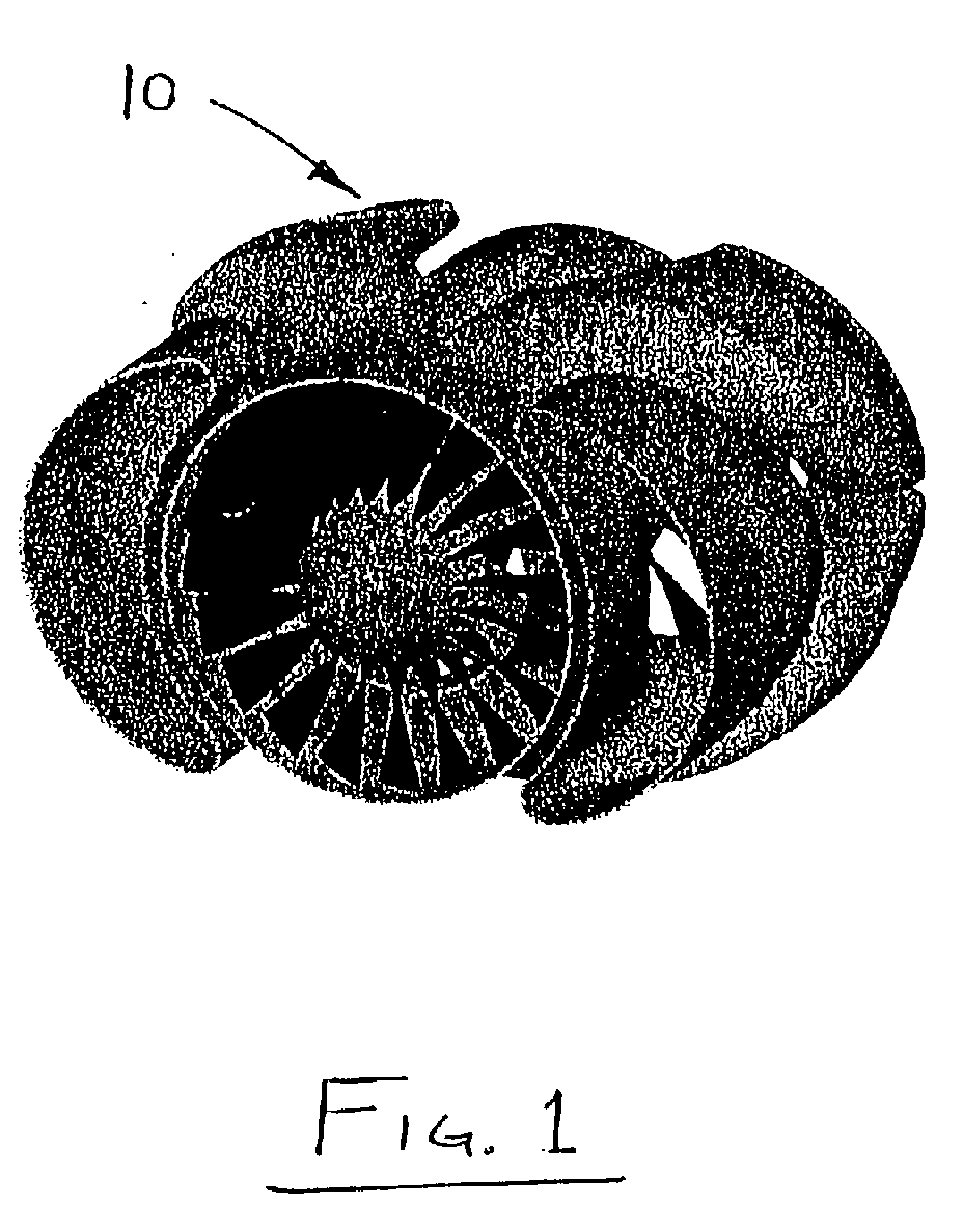
- the ducting system 10 of the present invention is intended for use on a gas turbine tangent having two fans connected to a common shaft.
- the ducting system 10 includes a single primary inlet duct 12, and four primary discharge ducts 14, 16, 18, 20.
- the primary inlet duct 12 includes a circular inlet port 22, as shown in Figure 6, and the primary inlet duct 12 has a constant flow area along its length.
- Each of the primary discharge ducts 14, 16, 18, 20 is integral with the primary inlet duct 12, and the circular inlet port 22 is located at one end of the primary inlet duct 12 distant from the primary discharge ducts 14, 16, 18, 20.
- Each of the primary discharge ducts 14, 16, 18, 20 has a primary discharge port 24, 26, 28, 30, as shown in Figure 15, located at one end thereof distant from the primary inlet duct 12.
- Each of the primary discharge ducts 14, 16, 18, 20, has a constant flow area throughout its length, and each of the primary discharge ducts 14, 16, 18, 20, has a flow area equal to one-fourth (0.25) of the flow area of the primary inlet duct 12.
- each of the primary discharge ports 24, 26, 28, 30 has a flow area equal to one-fourth (0.25) of the flow area of the circular inlet port 22.
- the ducting system 10 of the present invention also includes two secondary inlet ducts 32, 34 and a single secondary discharge duct 36.
- Each of the secondary inlet ducts 32, 34 is integral with the secondary discharge duct 36, and each of the secondary inlet ducts 32, 34 has an inlet port 38, 40 located at one end thereof distant from the secondary discharge duct 36, and the secondary discharge duct 36 has a circular secondary discharge port 42 located at one end thereof distant from the secondary inlet ducts 32, 34.
- the flow area of the secondary discharge duct 36 is constant along the length thereof, and the flow area of each of the secondary inlet ducts 32, 34 is constant along the length thereof.
- Each of the secondary inlet ducts 32, 34 has a flow area equal to one-half (0.5) of the circular secondary discharge duct 36.
- the flow area of each of the secondary inlet ports 38, 40 is equal to one-half (0.5) of the flow area of the circular secondary discharge port 42.
- the circular inlet port 22 and the circular discharge port 42 are coaxial, and the center 44 of the circular inlet port 22 and the center 46 of the circular discharge port 42 are both located on a reference axis 48 that is coaxial with the shaft shown in Figure 5.
- the secondary inlet ports 38, 40 are located radially outward of the circular inlet port 22 relative to the reference axis 48.
- the primary discharge ports 24, 26, 28, 30 are located radially outward of the circular discharge port 42 relative to the reference axis 48.
- the present invention can be used in combination with a gas turbine engine 100 having two fans 102, 104 connected to a single shaft as part of a propulsion system in which each of the fans 102, 104 has substantially the same diameter.
- the distance 50 between the fans 102, 104 is equal to three-fourths (0.75) of the diameter 52 of the fans 102, 104.
- the ducting system 10 of the present invention provides a smooth transition from the inlet ports 22, 38, 40 to the discharge ports 24, 26, 28, 30, 42.
Landscapes
- Engineering & Computer Science (AREA)
- Chemical & Material Sciences (AREA)
- Combustion & Propulsion (AREA)
- Mechanical Engineering (AREA)
- General Engineering & Computer Science (AREA)
- Structures Of Non-Positive Displacement Pumps (AREA)
Abstract
Description
a ducting system for use on a gas turbine engine having two fans connected to a common shaft, including a primary inlet duct that is integral with a plurality of primary discharge ducts , a plurality of secondary inlet ducts that are integral with a secondary discharge duct, and wherein one fan is located within the primary inlet duct and the other fan is located in the secondary discharge duct.
Claims (9)
- A ducting system for use on a gas turbine engine having two fans (102, 104) connected to a common shaft, said ducting system comprising:a single primary inlet duct (12) and four primary discharge ducts (14, 16, 18, 20), each of said primary discharge ducts (14, 16, 18, 20) is integral with said primary duct (12), said primary inlet duct having a circular primary inlet port located at one end thereof distant from said primary discharge ducts (14, 16, 18, 20), and each of said primary discharge ducts (14, 16, 18, 20) having a primary discharge port located at one end thereof distant from said primary inlet duct (12);two secondary inlet ducts (32, 34) and a single secondary discharge duct (36), each of said secondary inlet ducts (32, 34) is integral with said secondary discharge duct (36), each of said secondary inlet ducts (32, 34) having a secondary inlet port located at one end thereof distant from said secondary discharge duct (36), and said secondary discharge duct (36) having a circular secondary discharge port located at one end thereof distant from said secondary inlet ducts (32, 34);a reference axis (48);wherein the center of the circular primary inlet port and the center of the circular secondary discharge port are both located on said reference axis (48), said secondary inlet ports are located radially outward of said circular primary inlet port relative to said reference axis (48), and said primary discharge ports are located radially outward of said circular secondary discharge port relative to said reference axis (48).
- The ducting system of claim 1 wherein the flow area of the primary inlet duct (12) is constant along the length thereof, the flow area of each of the primary discharge ducts (14, 16, 18, 20) is constant along the length thereof, and the flow area of each of the primary discharge ports is equal to one-fourth of the flow area of the circular primary inlet port.
- The ducting system of claim 2 wherein the flow area of the secondary discharge duct (36) is constant along the length thereof, the flow area of each of the secondary inlet ducts (32, 34) is constant along the length thereof, and the flow area of each of the secondary inlet ports is equal to one-half of the flow area of the circular secondary discharge port.
- A propulsion system comprising:a gas turbine engine having two fans (102, 104) connected to a single shaft, each of said fans having substantially the same diameter;a single primary inlet (12) duct and four primary discharge ducts (14, 16, 18, 20), each of said primary discharge ducts (14, 16, 18, 20) is integral with said primary duct (12), said primary inlet duct having a circular primary inlet port located at one end thereof distant from said primary discharge ducts (14, 16, 18, 20), and each of said primary discharge ducts (14, 16, 18, 20) having a primary discharge port located at one end thereof distant from said primary inlet duct (12);two secondary inlet ducts (32, 34) and a single secondary discharge duct (36), each of said secondary inlet ducts (32, 34) is integral with said secondary discharge duct (36), each of said secondary inlet ducts (32, 34) having a secondary inlet port located at one end thereof distant from said secondary discharge duct (36), and said secondary discharge duct (36) having a circular secondary discharge port located at one end thereof distant from said secondary inlet ducts (32, 34);a reference axis (48);wherein the center of the circular primary inlet port and the center of the circular secondary discharge port are both located on said reference axis (48), said secondary inlet ports are located radially outward of said circular primary inlet port relative to said reference axis (48), said primary discharge ports are located radially outward of said circular secondary discharge port relative to said reference axis, one of said fans (102, 104) is located in said circular primary inlet port, and said other fan is located in said circular secondary discharge port.
- The propulsion system of claim 4 wherein the flow area of the primary inlet duct (12) is constant along the length thereof, the flow area of each of the primary discharge ducts (14, 16, 18, 20) is constant along the length thereof, and the flow area of each of the primary discharge ports is equal to one-fourth of the flow area of the circular primary inlet port.
- The propulsion system of claim 5 wherein the flow area of the secondary discharge duct (36) is constant along the length thereof, the flow area of each of the secondary inlet ducts (32, 34) is constant along the length thereof, and the flow area of each of the secondary inlet ports is equal to one-half of the flow area of the circular secondary discharge port.
- A ducting system for use on a gas turbine engine having two fans (102, 104) connected to a common shaft, including a primary inlet duct (12) that is integral with a plurality of primary discharge ducts (14, 16, 18, 20), a plurality of secondary inlet ducts (32, 34) that are integral with a secondary discharge duct (36), and wherein one fan (102) is located within the primary inlet duct (12) and the other fan (104) is located in the secondary discharge duct (36).
- The ducting system of claim 7 wherein each of the ducts includes a port, the ports of the secondary inlet ducts are located radially outward of the port of the primary inlet duct, and the ports of the primary discharge ducts are located radially outward of the port of the secondary discharge duct.
- The ducting system of claim 7 or 8 comprising four primary discharge ducts (14,16,18,20) and two secondary inlet ducts (37,34).
Applications Claiming Priority (2)
| Application Number | Priority Date | Filing Date | Title |
|---|---|---|---|
| US475877 | 1983-03-16 | ||
| US09/475,877 US6351940B1 (en) | 1999-12-30 | 1999-12-30 | Inverter ducting for dual fan concept |
Publications (3)
| Publication Number | Publication Date |
|---|---|
| EP1113162A2 true EP1113162A2 (en) | 2001-07-04 |
| EP1113162A3 EP1113162A3 (en) | 2003-01-02 |
| EP1113162B1 EP1113162B1 (en) | 2005-10-12 |
Family
ID=23889534
Family Applications (1)
| Application Number | Title | Priority Date | Filing Date |
|---|---|---|---|
| EP00311379A Expired - Lifetime EP1113162B1 (en) | 1999-12-30 | 2000-12-19 | Ducting for duel fan concept |
Country Status (5)
| Country | Link |
|---|---|
| US (1) | US6351940B1 (en) |
| EP (1) | EP1113162B1 (en) |
| JP (1) | JP2001207911A (en) |
| KR (1) | KR20010070361A (en) |
| DE (1) | DE60023093T2 (en) |
Cited By (3)
| Publication number | Priority date | Publication date | Assignee | Title |
|---|---|---|---|---|
| EP1607612A1 (en) * | 2004-05-28 | 2005-12-21 | Rolls-Royce Plc | Gas turbine engine |
| US7055306B2 (en) | 2003-04-30 | 2006-06-06 | Hamilton Sundstrand Corporation | Combined stage single shaft turbofan engine |
| EP3187723A1 (en) * | 2015-12-29 | 2017-07-05 | General Electric Company | Method and system for in-line distributed propulsion |
Families Citing this family (6)
| Publication number | Priority date | Publication date | Assignee | Title |
|---|---|---|---|---|
| JP5092143B2 (en) * | 2008-03-07 | 2012-12-05 | 独立行政法人 宇宙航空研究開発機構 | High bypass ratio turbofan jet engine |
| US9777631B2 (en) * | 2011-09-30 | 2017-10-03 | General Electric Company | Conformal inlet apparatus for a gas turbine engine |
| US10247097B2 (en) | 2012-12-10 | 2019-04-02 | United Technologies Corporation | Gas turbine engine with plural accessory air paths |
| FR3012417B1 (en) * | 2013-10-31 | 2016-12-09 | Snecma | TURBOREACTOR NACELLE |
| US10794281B2 (en) * | 2016-02-02 | 2020-10-06 | General Electric Company | Gas turbine engine having instrumented airflow path components |
| EP3609006A1 (en) * | 2018-08-09 | 2020-02-12 | SOLIDpower SA | Sofc system with anode off-gas recirculation |
Family Cites Families (8)
| Publication number | Priority date | Publication date | Assignee | Title |
|---|---|---|---|---|
| US3096954A (en) * | 1960-11-10 | 1963-07-09 | Snecma | Improvements to jet-propelled aircraft with directional discharge-nozzles for vertical take-off |
| US3792584A (en) * | 1972-02-16 | 1974-02-19 | Boeing Co | Increased or variable bypass ratio engines |
| US4054030A (en) * | 1976-04-29 | 1977-10-18 | General Motors Corporation | Variable cycle gas turbine engine |
| US4222234A (en) * | 1977-07-25 | 1980-09-16 | General Electric Company | Dual fan engine for VTOL pitch control |
| US4290262A (en) * | 1978-12-11 | 1981-09-22 | United Technologies Corporation | Two-dimensional plug nozzle |
| GB2192940B (en) * | 1986-07-25 | 1990-10-31 | Rolls Royce Plc | A variable area aircraft air intake |
| FR2645911B1 (en) * | 1989-04-18 | 1991-06-07 | Snecma | HIGH DILUTION MOTOR WITH UPSTREAM BLOWER AND DOWNSTREAM BLOWER |
| GB8924871D0 (en) * | 1989-11-03 | 1989-12-20 | Rolls Royce Plc | Tandem fan engine |
-
1999
- 1999-12-30 US US09/475,877 patent/US6351940B1/en not_active Expired - Lifetime
-
2000
- 2000-12-19 DE DE60023093T patent/DE60023093T2/en not_active Expired - Lifetime
- 2000-12-19 EP EP00311379A patent/EP1113162B1/en not_active Expired - Lifetime
- 2000-12-27 KR KR1020000082883A patent/KR20010070361A/en not_active Abandoned
- 2000-12-27 JP JP2000396998A patent/JP2001207911A/en not_active Withdrawn
Cited By (4)
| Publication number | Priority date | Publication date | Assignee | Title |
|---|---|---|---|---|
| US7055306B2 (en) | 2003-04-30 | 2006-06-06 | Hamilton Sundstrand Corporation | Combined stage single shaft turbofan engine |
| EP1607612A1 (en) * | 2004-05-28 | 2005-12-21 | Rolls-Royce Plc | Gas turbine engine |
| US7500352B2 (en) | 2004-05-28 | 2009-03-10 | Rolls-Royce Plc | Gas turbine engine |
| EP3187723A1 (en) * | 2015-12-29 | 2017-07-05 | General Electric Company | Method and system for in-line distributed propulsion |
Also Published As
| Publication number | Publication date |
|---|---|
| US6351940B1 (en) | 2002-03-05 |
| DE60023093T2 (en) | 2006-04-20 |
| EP1113162A3 (en) | 2003-01-02 |
| DE60023093D1 (en) | 2006-02-23 |
| JP2001207911A (en) | 2001-08-03 |
| EP1113162B1 (en) | 2005-10-12 |
| KR20010070361A (en) | 2001-07-25 |
Similar Documents
| Publication | Publication Date | Title |
|---|---|---|
| US6488469B1 (en) | Mixed flow and centrifugal compressor for gas turbine engine | |
| US7451592B2 (en) | Counter-rotating turbine engine including a gearbox | |
| US7178338B2 (en) | Variable area nozzle | |
| EP2098714B1 (en) | High bypass-ratio turbofan jet engine | |
| US7891163B2 (en) | Engine | |
| EP2520763B1 (en) | Impeller | |
| EP1624169B1 (en) | Fan assembly for a gas turbine | |
| CA1094527A (en) | Multi-bladed, high speed prop-fan | |
| EP2218874B1 (en) | Turbine vane airfoil with turning flow and axial/circumferential trailing edge configuration | |
| EP1731734A2 (en) | Counterrotating turbofan engine | |
| JPS5812899A (en) | Composite propeller | |
| EP2685065A2 (en) | A gas turbine engine | |
| CN113446117A (en) | High pressure ratio gas turbine engine | |
| CN110651112A (en) | Turbine with fan rotor and reduction gearbox driving low pressure compressor shaft | |
| EP1050678A2 (en) | Exhaust vane | |
| CA1263242A (en) | Gas turbine outlet arrangement | |
| CN111878254A (en) | Gas turbine engine | |
| CN110953071A (en) | Air inlet of nacelle | |
| EP1113162B1 (en) | Ducting for duel fan concept | |
| US10947929B2 (en) | Integrated aircraft propulsion system | |
| CN111878257B (en) | turbo engine | |
| CN110821574A (en) | Gas turbine engine mounting arrangement | |
| CN112459923B (en) | Turbofan core and bypass arrangement | |
| JP3012661B2 (en) | Ducted fan gas turbine engine and fan | |
| CN111878258A (en) | Gas turbine engine with core mount |
Legal Events
| Date | Code | Title | Description |
|---|---|---|---|
| PUAI | Public reference made under article 153(3) epc to a published international application that has entered the european phase |
Free format text: ORIGINAL CODE: 0009012 |
|
| AK | Designated contracting states |
Kind code of ref document: A2 Designated state(s): AT BE CH CY DE DK ES FI FR GB GR IE IT LI LU MC NL PT SE TR |
|
| AX | Request for extension of the european patent |
Free format text: AL;LT;LV;MK;RO;SI |
|
| PUAL | Search report despatched |
Free format text: ORIGINAL CODE: 0009013 |
|
| AK | Designated contracting states |
Kind code of ref document: A3 Designated state(s): AT BE CH CY DE DK ES FI FR GB GR IE IT LI LU MC NL PT SE TR |
|
| AX | Request for extension of the european patent |
Free format text: AL;LT;LV;MK;RO;SI |
|
| 17P | Request for examination filed |
Effective date: 20030120 |
|
| 17Q | First examination report despatched |
Effective date: 20030515 |
|
| AKX | Designation fees paid |
Designated state(s): DE FR GB |
|
| GRAP | Despatch of communication of intention to grant a patent |
Free format text: ORIGINAL CODE: EPIDOSNIGR1 |
|
| GRAS | Grant fee paid |
Free format text: ORIGINAL CODE: EPIDOSNIGR3 |
|
| GRAA | (expected) grant |
Free format text: ORIGINAL CODE: 0009210 |
|
| AK | Designated contracting states |
Kind code of ref document: B1 Designated state(s): DE FR GB |
|
| REG | Reference to a national code |
Ref country code: GB Ref legal event code: FG4D |
|
| REF | Corresponds to: |
Ref document number: 60023093 Country of ref document: DE Date of ref document: 20060223 Kind code of ref document: P |
|
| ET | Fr: translation filed | ||
| PLBE | No opposition filed within time limit |
Free format text: ORIGINAL CODE: 0009261 |
|
| STAA | Information on the status of an ep patent application or granted ep patent |
Free format text: STATUS: NO OPPOSITION FILED WITHIN TIME LIMIT |
|
| 26N | No opposition filed |
Effective date: 20060713 |
|
| PGFP | Annual fee paid to national office [announced via postgrant information from national office to epo] |
Ref country code: FR Payment date: 20081205 Year of fee payment: 9 |
|
| REG | Reference to a national code |
Ref country code: FR Ref legal event code: ST Effective date: 20100831 |
|
| PG25 | Lapsed in a contracting state [announced via postgrant information from national office to epo] |
Ref country code: FR Free format text: LAPSE BECAUSE OF NON-PAYMENT OF DUE FEES Effective date: 20091231 |
|
| PGFP | Annual fee paid to national office [announced via postgrant information from national office to epo] |
Ref country code: DE Payment date: 20121213 Year of fee payment: 13 |
|
| PGFP | Annual fee paid to national office [announced via postgrant information from national office to epo] |
Ref country code: GB Payment date: 20121219 Year of fee payment: 13 |
|
| REG | Reference to a national code |
Ref country code: DE Ref legal event code: R119 Ref document number: 60023093 Country of ref document: DE |
|
| GBPC | Gb: european patent ceased through non-payment of renewal fee |
Effective date: 20131219 |
|
| REG | Reference to a national code |
Ref country code: DE Ref legal event code: R119 Ref document number: 60023093 Country of ref document: DE Effective date: 20140701 |
|
| PG25 | Lapsed in a contracting state [announced via postgrant information from national office to epo] |
Ref country code: DE Free format text: LAPSE BECAUSE OF NON-PAYMENT OF DUE FEES Effective date: 20140701 |
|
| PG25 | Lapsed in a contracting state [announced via postgrant information from national office to epo] |
Ref country code: GB Free format text: LAPSE BECAUSE OF NON-PAYMENT OF DUE FEES Effective date: 20131219 |