EP1112848A2 - Continuous ink jet printer with micro-valve deflection mechanism and method of making same - Google Patents
Continuous ink jet printer with micro-valve deflection mechanism and method of making same Download PDFInfo
- Publication number
- EP1112848A2 EP1112848A2 EP00204443A EP00204443A EP1112848A2 EP 1112848 A2 EP1112848 A2 EP 1112848A2 EP 00204443 A EP00204443 A EP 00204443A EP 00204443 A EP00204443 A EP 00204443A EP 1112848 A2 EP1112848 A2 EP 1112848A2
- Authority
- EP
- European Patent Office
- Prior art keywords
- ink
- primary
- nozzle bore
- stream
- chamber
- Prior art date
- Legal status (The legal status is an assumption and is not a legal conclusion. Google has not performed a legal analysis and makes no representation as to the accuracy of the status listed.)
- Granted
Links
- 238000004519 manufacturing process Methods 0.000 title claims abstract description 10
- 230000007246 mechanism Effects 0.000 title description 3
- 239000000758 substrate Substances 0.000 claims abstract description 27
- 239000000463 material Substances 0.000 claims abstract description 18
- XUIMIQQOPSSXEZ-UHFFFAOYSA-N Silicon Chemical compound [Si] XUIMIQQOPSSXEZ-UHFFFAOYSA-N 0.000 claims abstract description 11
- 229910052710 silicon Inorganic materials 0.000 claims abstract description 11
- 239000010703 silicon Substances 0.000 claims abstract description 11
- 238000000034 method Methods 0.000 claims description 21
- 238000000151 deposition Methods 0.000 claims description 14
- 238000005530 etching Methods 0.000 claims description 7
- 239000011248 coating agent Substances 0.000 claims description 4
- 238000000576 coating method Methods 0.000 claims description 4
- 238000000059 patterning Methods 0.000 claims description 4
- 238000007639 printing Methods 0.000 description 11
- 230000015572 biosynthetic process Effects 0.000 description 5
- 238000007641 inkjet printing Methods 0.000 description 5
- 238000012546 transfer Methods 0.000 description 5
- 239000004642 Polyimide Substances 0.000 description 3
- 238000007600 charging Methods 0.000 description 3
- 229910052751 metal Inorganic materials 0.000 description 3
- 239000002184 metal Substances 0.000 description 3
- 229920001721 polyimide Polymers 0.000 description 3
- 238000004064 recycling Methods 0.000 description 3
- 239000000126 substance Substances 0.000 description 3
- PXHVJJICTQNCMI-UHFFFAOYSA-N Nickel Chemical compound [Ni] PXHVJJICTQNCMI-UHFFFAOYSA-N 0.000 description 2
- 229910018503 SF6 Inorganic materials 0.000 description 2
- 229910052581 Si3N4 Inorganic materials 0.000 description 2
- QVGXLLKOCUKJST-UHFFFAOYSA-N atomic oxygen Chemical compound [O] QVGXLLKOCUKJST-UHFFFAOYSA-N 0.000 description 2
- 239000003989 dielectric material Substances 0.000 description 2
- 238000007786 electrostatic charging Methods 0.000 description 2
- 238000005516 engineering process Methods 0.000 description 2
- 239000007788 liquid Substances 0.000 description 2
- 150000002739 metals Chemical class 0.000 description 2
- 229910052760 oxygen Inorganic materials 0.000 description 2
- 239000001301 oxygen Substances 0.000 description 2
- 238000005498 polishing Methods 0.000 description 2
- 229910021420 polycrystalline silicon Inorganic materials 0.000 description 2
- 229920005591 polysilicon Polymers 0.000 description 2
- 238000012545 processing Methods 0.000 description 2
- 230000001681 protective effect Effects 0.000 description 2
- HQVNEWCFYHHQES-UHFFFAOYSA-N silicon nitride Chemical compound N12[Si]34N5[Si]62N3[Si]51N64 HQVNEWCFYHHQES-UHFFFAOYSA-N 0.000 description 2
- SFZCNBIFKDRMGX-UHFFFAOYSA-N sulfur hexafluoride Chemical compound FS(F)(F)(F)(F)F SFZCNBIFKDRMGX-UHFFFAOYSA-N 0.000 description 2
- BLIQUJLAJXRXSG-UHFFFAOYSA-N 1-benzyl-3-(trifluoromethyl)pyrrolidin-1-ium-3-carboxylate Chemical compound C1C(C(=O)O)(C(F)(F)F)CCN1CC1=CC=CC=C1 BLIQUJLAJXRXSG-UHFFFAOYSA-N 0.000 description 1
- 229910000838 Al alloy Inorganic materials 0.000 description 1
- RYGMFSIKBFXOCR-UHFFFAOYSA-N Copper Chemical compound [Cu] RYGMFSIKBFXOCR-UHFFFAOYSA-N 0.000 description 1
- RTAQQCXQSZGOHL-UHFFFAOYSA-N Titanium Chemical compound [Ti] RTAQQCXQSZGOHL-UHFFFAOYSA-N 0.000 description 1
- 229910045601 alloy Inorganic materials 0.000 description 1
- 239000000956 alloy Substances 0.000 description 1
- 229910052782 aluminium Inorganic materials 0.000 description 1
- XAGFODPZIPBFFR-UHFFFAOYSA-N aluminium Chemical compound [Al] XAGFODPZIPBFFR-UHFFFAOYSA-N 0.000 description 1
- 230000000903 blocking effect Effects 0.000 description 1
- 238000007796 conventional method Methods 0.000 description 1
- 229910052802 copper Inorganic materials 0.000 description 1
- 239000010949 copper Substances 0.000 description 1
- 230000008021 deposition Effects 0.000 description 1
- 238000011161 development Methods 0.000 description 1
- 238000010586 diagram Methods 0.000 description 1
- 238000009792 diffusion process Methods 0.000 description 1
- 239000006185 dispersion Substances 0.000 description 1
- 230000005684 electric field Effects 0.000 description 1
- 239000011159 matrix material Substances 0.000 description 1
- 229910052759 nickel Inorganic materials 0.000 description 1
- 230000003287 optical effect Effects 0.000 description 1
- 238000007517 polishing process Methods 0.000 description 1
- 238000003825 pressing Methods 0.000 description 1
- 238000012552 review Methods 0.000 description 1
- 238000004528 spin coating Methods 0.000 description 1
- 229960000909 sulfur hexafluoride Drugs 0.000 description 1
- 229910052715 tantalum Inorganic materials 0.000 description 1
- GUVRBAGPIYLISA-UHFFFAOYSA-N tantalum atom Chemical compound [Ta] GUVRBAGPIYLISA-UHFFFAOYSA-N 0.000 description 1
- 239000010936 titanium Substances 0.000 description 1
- 229910052719 titanium Inorganic materials 0.000 description 1
- IGELFKKMDLGCJO-UHFFFAOYSA-N xenon difluoride Chemical compound F[Xe]F IGELFKKMDLGCJO-UHFFFAOYSA-N 0.000 description 1
Images



Classifications
-
- B—PERFORMING OPERATIONS; TRANSPORTING
- B41—PRINTING; LINING MACHINES; TYPEWRITERS; STAMPS
- B41J—TYPEWRITERS; SELECTIVE PRINTING MECHANISMS, i.e. MECHANISMS PRINTING OTHERWISE THAN FROM A FORME; CORRECTION OF TYPOGRAPHICAL ERRORS
- B41J2/00—Typewriters or selective printing mechanisms characterised by the printing or marking process for which they are designed
- B41J2/005—Typewriters or selective printing mechanisms characterised by the printing or marking process for which they are designed characterised by bringing liquid or particles selectively into contact with a printing material
- B41J2/01—Ink jet
- B41J2/015—Ink jet characterised by the jet generation process
- B41J2/02—Ink jet characterised by the jet generation process generating a continuous ink jet
- B41J2/03—Ink jet characterised by the jet generation process generating a continuous ink jet by pressure
-
- B—PERFORMING OPERATIONS; TRANSPORTING
- B41—PRINTING; LINING MACHINES; TYPEWRITERS; STAMPS
- B41J—TYPEWRITERS; SELECTIVE PRINTING MECHANISMS, i.e. MECHANISMS PRINTING OTHERWISE THAN FROM A FORME; CORRECTION OF TYPOGRAPHICAL ERRORS
- B41J2/00—Typewriters or selective printing mechanisms characterised by the printing or marking process for which they are designed
- B41J2/005—Typewriters or selective printing mechanisms characterised by the printing or marking process for which they are designed characterised by bringing liquid or particles selectively into contact with a printing material
- B41J2/01—Ink jet
- B41J2/07—Ink jet characterised by jet control
- B41J2/075—Ink jet characterised by jet control for many-valued deflection
- B41J2/08—Ink jet characterised by jet control for many-valued deflection charge-control type
- B41J2/09—Deflection means
-
- B—PERFORMING OPERATIONS; TRANSPORTING
- B41—PRINTING; LINING MACHINES; TYPEWRITERS; STAMPS
- B41J—TYPEWRITERS; SELECTIVE PRINTING MECHANISMS, i.e. MECHANISMS PRINTING OTHERWISE THAN FROM A FORME; CORRECTION OF TYPOGRAPHICAL ERRORS
- B41J2/00—Typewriters or selective printing mechanisms characterised by the printing or marking process for which they are designed
- B41J2/005—Typewriters or selective printing mechanisms characterised by the printing or marking process for which they are designed characterised by bringing liquid or particles selectively into contact with a printing material
- B41J2/01—Ink jet
- B41J2/07—Ink jet characterised by jet control
- B41J2/105—Ink jet characterised by jet control for binary-valued deflection
-
- B—PERFORMING OPERATIONS; TRANSPORTING
- B41—PRINTING; LINING MACHINES; TYPEWRITERS; STAMPS
- B41J—TYPEWRITERS; SELECTIVE PRINTING MECHANISMS, i.e. MECHANISMS PRINTING OTHERWISE THAN FROM A FORME; CORRECTION OF TYPOGRAPHICAL ERRORS
- B41J2/00—Typewriters or selective printing mechanisms characterised by the printing or marking process for which they are designed
- B41J2/005—Typewriters or selective printing mechanisms characterised by the printing or marking process for which they are designed characterised by bringing liquid or particles selectively into contact with a printing material
- B41J2/01—Ink jet
- B41J2/015—Ink jet characterised by the jet generation process
- B41J2/02—Ink jet characterised by the jet generation process generating a continuous ink jet
- B41J2/03—Ink jet characterised by the jet generation process generating a continuous ink jet by pressure
- B41J2002/032—Deflection by heater around the nozzle
-
- B—PERFORMING OPERATIONS; TRANSPORTING
- B41—PRINTING; LINING MACHINES; TYPEWRITERS; STAMPS
- B41J—TYPEWRITERS; SELECTIVE PRINTING MECHANISMS, i.e. MECHANISMS PRINTING OTHERWISE THAN FROM A FORME; CORRECTION OF TYPOGRAPHICAL ERRORS
- B41J2202/00—Embodiments of or processes related to ink-jet or thermal heads
- B41J2202/01—Embodiments of or processes related to ink-jet heads
- B41J2202/16—Nozzle heaters
-
- B—PERFORMING OPERATIONS; TRANSPORTING
- B41—PRINTING; LINING MACHINES; TYPEWRITERS; STAMPS
- B41J—TYPEWRITERS; SELECTIVE PRINTING MECHANISMS, i.e. MECHANISMS PRINTING OTHERWISE THAN FROM A FORME; CORRECTION OF TYPOGRAPHICAL ERRORS
- B41J2202/00—Embodiments of or processes related to ink-jet or thermal heads
- B41J2202/01—Embodiments of or processes related to ink-jet heads
- B41J2202/22—Manufacturing print heads
Definitions
- This invention relates generally to the field of digitally controlled printing devices, and in particular to continuous ink jet printheads which integrate multiple nozzles on a single substrate and in which print nonprint operation is effected by controlled deflection of the ink as it leaves the printhead nozzle.
- Inkjet printing has become recognized as a prominent contender in the digitally controlled, electronic printing arena because, e.g., of its non-impact, low-noise characteristics, its use of plain paper and its avoidance of toner transfers and fixing.
- Ink jet printing mechanisms can be categorized as either continuous ink jet or drop on demand ink jet. Continuous ink jet printing dates back to at least1929. See U.S. Patent No. 1,941,001 to Hansell.
- U.S. Patent No. 3,416,153 which issued to Hertz et al. in 1966, discloses a method of achieving variable optical density of printed spots in continuous ink jet printing using the electrostatic dispersion of a charged drop stream to modulate the number of droplets which pass through a small aperture. This technique is used in ink jet printers manufactured by Iris.
- U.S. Patent No. 3,878,519 which issued to Eaton in 1974, discloses a method and apparatus for synchronizing droplet formation in a liquid stream using electrostatic deflection by a charging tunnel and deflection plates.
- US Patent No. 4,346,387 which issued to Hertz in 1982 discloses a method and apparatus for controlling the electric charge on droplets formed by the breaking up of a pressurized liquid stream at a drop formation point located within the electric field having an electric potential gradient. Drop formation is effected at a point in the field corresponding to the desired predetermined charge to be placed on the droplets at the point of their formation. In addition to charging rings, deflection plates are used to deflect the drops.
- apparatus for controlling ink in a continuous ink jet printer in which a continuous stream of ink is emitted from a nozzle
- the apparatus comprises a reservoir of pressurized ink, an ink staging chamber having a nozzle bore to establish a continuous flow of ink in a stream, ink delivery means intermediate said reservoir and said staging chamber for communicating ink between said reservoir and said staging chamber, said channel means comprising a primary ink delivery channel and an adjacent secondary ink delivery channel; and a thermally actuated valve positioned, when closed, to block ink flow through said secondary channel and, when opened, to permit ink flow through said secondary channel, whereby opening and closing of said valve results in deflection of said ink stream between a print direction and a non-print direction.
- a method of fabricating a continuous inkjet printhead having a series of inkjet devices each of which includes primary and secondary ink delivery channels, an ink staging chamber having a chamber wall with a nozzle bore aligned with said primary ink delivery channel and a thermally actuated valve positioned over said secondary delivery channel to control, by opening and closing of said valve, deflection of an ink stream emitted from said nozzle bore between print and non-print directions.
- the fabrication method comprises providing a silicon substrate having a front side and a back side; forming a series of first and second adjacent wells in the substrate corresponding to said primary and secondary ink delivery channels; and depositing a patterned thermally actuated valve device over each of said second wells.
- the method also includes depositing and patterning sacrificial material over said wells to form a volume corresponding to said ink staging chamber; depositing a chamber wall material over said sacrificial material to define an ink staging chamber wall; etching a nozzle bore in the chamber wall aligned with said first well; and removing said sacrificial material through said nozzle bore thereby forming said ink staging chamber with said valve device released within the chamber.
- the method further includes etching a channel through the back side of said substrate to said wells to form said primary and secondary ink delivery channels to said ink staging chamber.
- FIG. 1 shows a simplified block schematic diagram of one exemplary printing apparatus according to the present invention.
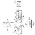
- FIG. 2 shows in schematic form a cross-section of a segment of a continuous ink jet printhead illustrating principles of the present invention.
- FIGS. 3 - 17 show in schematic form the steps employed in a method of producing a continuous ink jet printhead in accordance with a feature of the invention.
- a continuous ink jet printer system includes an image source 10 such as a scanner or computer which provides raster image data, outline image data in the form of a page description language, or other forms of digital image data.
- This image data is converted to half-toned bitmap image data by an image processing unit 12 which also stores the image data in memory.
- a plurality of valve control circuits 14 read data from the image memory and apply time-varying electrical pulses to a set of electrically controlled micro-valves that are part of a printhead 16. These pulses are applied at an appropriate time, and to the appropriate nozzle in the printhead, so that drops formed from a continuous ink jet stream will form spots on a recording medium 18 in the appropriate position designated by the data in the image memory.
- Recording medium 18 is moved relative to printhead 16 by a recording medium transport system 20, and which is electronically controlled by a recording medium transport control system 22, which in turn is controlled by a micro-controller 24.
- the recording medium transport system shown in Figure 1 is a schematic only, and many different mechanical configurations are possible.
- a transfer roller could be used as recording medium transport system 20 to facilitate transfer of the ink drops to recording medium 18.
- Such transfer roller technology is well known in the art.
- Micro-controller 24 may also control an ink pressure regulator 26 and valve control circuits 14.
- Ink is contained in an ink reservoir 28 under pressure. In the non-printing state, continuous ink jet drop streams are unable to reach recording medium 18 due to an ink gutter 17 that blocks the stream and which may allow a portion of the ink to be recycled by an ink recycling unit 19.
- the ink recycling unit reconditions the ink and feeds it back to reservoir 28.
- Such ink recycling units are well known in the art.
- the ink pressure suitable for optimal operation will depend on a number of factors, including geometry and thermal properties of the nozzles and thermal properties of the ink. A constant ink pressure can be achieved by applying pressure to ink reservoir 28 under the control of ink pressure regulator 26.
- the ink is distributed to the back surface of printhead 16 by an ink channel device 30.
- the ink preferably flows through slots and/or holes etched through a silicon substrate of printhead 16 to its front surface, where a plurality of nozzles and heaters are situated.
- FIG. 2 a segment of printhead 16 is shown schematically in cross-section.
- the printhead includes an ink staging chamber 40 having a nozzle bore 42 from which ink under pressure is emitted in a stream directed toward the recording medium 18.
- the pressurized ink from reservoir 28 is communicated via the channel device 30 to the staging chamber 40 by ink delivery channel means 30 which, for each ink jet nozzle comprises a primary ink delivery channel 44 and an adjacent secondary ink delivery channel 46.
- a thermally actuated valve 50 shown in solid line, is positioned within the staging chamber 40 over the secondary channel 46 thereby blocking the flow of ink through the secondary channel 46.
- the pressurized ink flowing through the primary channel 44 is emitted through nozzle bore 42 without deflection as stream 52 shown in solid line.
- the nozzle bore 42 is preferably axially aligned with the primary ink delivery channel 44 and the secondary ink delivery channel is axially offset from the primary channel in a direction opposite to the desired deflection direction of ink stream as represented by dotted outline 52a.
- valve 50 is thermally actuated by signals from valve control circuits 14 to raise up as shown by dotted lines 50a, pressurized ink flows through secondary channel 46 creating a lateral flow through the staging chamber 40 that combines with the ink flowing axially through the primary channel 44 to the nozzle bore 42.
- an oxide layer 80 preferably in the thickness range of from 0.1 to 1.0 micron, is formed on a silicon substrate 82.
- This oxide layer is patterned and etched to form an array of rectangular shaped openings 84 as seen in the plan view of FIG 4.
- the openings may be staggered as shown in order to allow for access to electrical contact terminals from opposite sides of the substrate. It will be appreciated that these figures are schematic in nature to illustrate the steps of the fabrication process and are not drawn to scale.
- a resist layer 86 is next applied to the substrate 82 as shown in FIG.
- substrate wells 90 and 92 are formed as a cylindrical hole while well 92 is formed as a rectangular slot, although it will be appreciated that other configurations may be employed.
- the resist layer 86 is stripped and a conformal second oxide layer 94 is grown on the substrate 82. Since the 2 nd oxide layer is thermally grown the growth takes place at the substrate 82, 1 st oxide layer 80 interface. So realistically this is where the 2 nd oxide layer is formed, under the 1 st oxide layer with thickness in the range of from 0.1 to 1 micron.
- a first sacrificial layer 100 is deposited. The deposited thickness is enough to completely fill substrate wells 90 and 92 as well as the rectangular-shaped openings of modified oxide layer 80. In the preferred embodiment this layer is polysilicon. Alternatively, polyimide may be used.
- the first sacrificial layer 100 is then made planar to oxide layer 80 in FIG. 9 by chemical mechanical polishing. The chemical mechanical polishing process is designed to etch the first sacrificial layer 100 and stop on the modified oxide layer 80 creating a planarized first sacrificial layer 100a.
- a third oxide layer 102 is then deposited preferably in the thickness range of from 0.1 to 1 micron. This is followed by deposition and patterning of a lower valve actuator layer 104 as shown in FIGS 10 and 11.
- the criteria for the lower thermal actuator layer 104 are i) high coefficient of thermal expansion; ii) resistivity between 3-1000 ⁇ -cm; iii) high modulus of elasticity; iv) low mass density; and v) low specific heat.
- Metals such as aluminum, copper, nickel, titanium, and tantalum, as well as alloys of these metals meet these requirements. In the preferred embodiment, the metal is an aluminum alloy.
- an upper actuator layer 106 is then deposited and then removed in the areas above the planarized first sacrificial layer 100a except for the material deposited on the lower actuator layer 104 and a small protective region 106a adjacent the lower actuator layer 104.
- the third oxide layer 102 not protected by the upper actuator layer 106 is also removed during this step.
- the criteria for the upper actuator layer 106 are i) low coefficient of thermal expansion; and ii) the layer should be electrically insulating. Dielectric materials such as oxides and silicon nitride meet these requirements. In the preferred embodiment, the dielectric material is an oxide.
- the protective region 106a, along with the third oxide layer 102, completely encloses the lower actuator layer 90, protecting it from the ink.
- a second sacrificial layer 110 is deposited and lithographically patterned.
- the second sacrificial layer encloses the rectangular shaped opening 84 (FIG. 13b) including the thermally actuated valve 50 and substrate well 90, 92.
- this material is photo-imageable polyimide.
- This material can be spun on and patterned by masked exposure and development.
- the material is then final cured at 350C to provide a layer preferably in the thickness range 2-10 microns. A slight etchback in an oxygen plasma can be performed to adjust the final thickness and descum the surface.
- the volume occupied by this second sacrificial layer will become the in ink staging chamber 40 (FIG. 2).
- a thick chamber wall layer 112 is then deposited with a preferred thickness so that all regions between the second sacrificial layer 110 will be filled up and result in a thickness on top of the second sacrificial layer 110 that is greater than 1 micron.
- this material is an oxide layer.
- Other materials such as silicon nitride or oxynitrides can be used as well as combinations of this material to form the chamber wall layer 112.
- This layer can then be planarized by chemical mechanical polishing with a preferred final thickness of the chamber wall layer 112 above the second sacrificial layer 110 to be greater than 1 micron.
- the chamber wall layer 112 is next patterned and etched to form the nozzle bore 42 for the ejection of ink.
- the etch process also opens up a through-hole 116 in the chamber wall as well as in the upper actuator layer 106 so that electrical contact can be made to the lower actuator layer 104 which in turn activates the thermally actuated valve 50.
- the back side of the silicon substrate 82 is then patterned and ink feed channels 30 are etched into the silicon substrate 10 until they meet the liner oxide 94 coating the bottoms of the wells 90 and 92.
- the first sacrificial layer 100a, and second sacrificial layer 110 are then removed through the nozzle bore 42 with plasma etchants which do not attack the chamber wall layer112.
- This step will create the ink staging chamber 40, clear away the sacrificial layer from wells 90 and 92, and release the thermal actuator 50 (FIG.2) comprised of lower actuator layer 104 and upper actuator layer 106.
- the thermal actuator 50 (FIG.2) comprised of lower actuator layer 104 and upper actuator layer 106.
- an oxygen plasma is used for polyimide sacrificial layers.
- polysilicon sacrificial layers XeF 2 (Xenon Difluoride) or SF 6 (Sulfur Hexafluoride) is used.
- the liner oxide 94 coating the bottoms of the wells 90 and 92 is removed by etching from the back of the silicon substrate 10 thereby creating the primary and secondary ink delivery channels 44 and 46 (FIG 17).
- the bottom layer 104 of the actuator will be in a state of tensile stress that will cause the actuator to bend towards the opening of the secondary ink delivery channel thereby minimizing any leakage while the actuator is in the off (closed) state. More importantly, some minimal leakage can be tolerated in the off state. Such minimal leakage will cause a slight deflection of the ink stream 52 resulting in an initial deflection bias. However, this will not significantly affect the operation since what is most important is the change in deflection of the ink stream between the closed and open state of the thermal actuator.
Landscapes
- Particle Formation And Scattering Control In Inkjet Printers (AREA)
Abstract
Description
Claims (5)
- Apparatus for controlling ink in a continuous ink jet printer in which a continuous stream of ink is emitted from a nozzle bore (42); said apparatus comprising:a reservoir of pressurized ink;an ink staging chamber (40) having a nozzle bore (42) to establish a continuous flow of ink in a stream;ink delivery means intermediate said reservoir (28) and said staging chamber (40) for communicating ink between said reservoir and said staging chamber, said channel means comprising a primary ink delivery channel (44) and an adjacent secondary ink delivery channel (46); anda thermally actuated valve (50) positioned, when closed, to block ink flow through said secondary channel and, when opened, to permit ink flow through said secondary channel (46);whereby opening and closing of said valve results in deflection of said ink stream (52) between a print direction and a non-print direction.
- The apparatus of claim 1 wherein said nozzle bore is aligned with said primary ink delivery channel and said secondary ink delivery channel is offset from said primary ink delivery channel in a direction opposite to the deflection direction of said ink stream.
- Method of fabricating a continuous inkjet printhead having a series of inkjet devices each of which includes primary and secondary ink delivery channels, an ink staging chamber having a chamber wall with a nozzle bore aligned with said primary ink delivery channel and a thermally actuated valve positioned over said secondary delivery channel to control, by opening and closing of said valve, deflection of an ink stream emitted from said nozzle bore between print and non-print directions; the fabrication method comprising:providing a silicon substrate having a front side and a back side;forming a series of first and second adjacent wells in the substrate corresponding to said primary and secondary ink delivery channels;depositing a patterned thermally actuated valve device over each of said second wells;depositing and patterning sacrificial material over said wells to form a volume corresponding to said ink staging chamber;depositing a chamber wall material over said sacrificial material to define an ink staging chamber wall;etching a nozzle bore in the chamber wall aligned with said first well;removing said sacrificial material through said nozzle bore thereby forming said ink staging chamber with said valve device released within the chamber; andetching a channel through the back side of said substrate to said wells to form said primary and secondary ink delivery channels to said ink staging chamber.
- A method of fabricating a continuous ink jet printhead having provision for controlling deflection of an inkjet stream between print and non-print directions, the method comprising:providing a silicon substrate having a front side and a back side;depositing a first oxide layer on the front side of the substrate patterned and etched to form a series of openings;providing a resist layer in said openings patterned and etched to form first and second adjacent wells in each opening corresponding to primary and secondary ink delivery channels in the printhead;growing a conformal second oxide layer coating covering at least exposed surfaces of said substrate in said openings, including interior surfaces of said wells;depositing a first sacrificial layer filling said wells to a level planar with said second oxide coating;depositing a third oxide layer over saiddepositing a first electrically conductive actuator layer patterned to cover said second well;depositing a second electrically insulative actuator layer in a pattern that encases said first actuator layer;depositing a second sacrificial layer patterned to form a volume corresponding to an ink staging chamber in the printhead;depositing a thick oxide chamber wall layer over the patterned second sacrificial layer to thereby define a wall for said ink staging volume;patterning and etching an ink nozzle bore in chamber wall opposite said first well;removing said first and second sacrificial layers through said ink nozzle bore to thereby form said ink staging volume with said valve actuator released within said chamber; andetching the backside of the substrate and the second oxide layer in the bottoms to form said primary and secondary ink feed channels to said ink staging chamber.
- A method of controlling deflection of an ink stream emitted from a continuous flow ink jet print head comprising;passing a primary flow of ink from a pressurized ink reservoir via a primary ink delivery channel through an ink staging chamber to a nozzle bore to create emission of an undeflected ink stream from the print head; andcontrollably passing a secondary flow of ink from said pressurized ink reservoir via a secondary ink delivery channel through said ink staging chamber to said nozzle bore to create a lateral flow of ink which impinges said primary flow of ink in the staging chamber to thereby cause said emitted ink stream to be deflected in a direction away from said impinging lateral flow of ink.
Applications Claiming Priority (2)
| Application Number | Priority Date | Filing Date | Title |
|---|---|---|---|
| US468987 | 1999-12-21 | ||
| US09/468,987 US6474795B1 (en) | 1999-12-21 | 1999-12-21 | Continuous ink jet printer with micro-valve deflection mechanism and method of controlling same |
Publications (3)
| Publication Number | Publication Date |
|---|---|
| EP1112848A2 true EP1112848A2 (en) | 2001-07-04 |
| EP1112848A3 EP1112848A3 (en) | 2002-07-31 |
| EP1112848B1 EP1112848B1 (en) | 2004-05-12 |
Family
ID=23861989
Family Applications (1)
| Application Number | Title | Priority Date | Filing Date |
|---|---|---|---|
| EP00204443A Expired - Lifetime EP1112848B1 (en) | 1999-12-21 | 2000-12-11 | Continuous ink jet printer with micro-valve deflection mechanism and method of making same |
Country Status (4)
| Country | Link |
|---|---|
| US (3) | US6474795B1 (en) |
| EP (1) | EP1112848B1 (en) |
| JP (1) | JP2001199062A (en) |
| DE (1) | DE60010638T2 (en) |
Cited By (7)
| Publication number | Priority date | Publication date | Assignee | Title |
|---|---|---|---|---|
| EP1219425A3 (en) * | 2000-12-29 | 2003-03-26 | Eastman Kodak Company | Cmos/mems integrated ink jet print head with oxide based lateral flow nozzle architecture and method of forming same |
| EP1219424A3 (en) * | 2000-12-29 | 2003-05-14 | Eastman Kodak Company | Cmos/mems integrated ink jet print head with silicon based lateral flow nozzle architecture and method of forming same |
| EP1329319A1 (en) * | 2002-01-17 | 2003-07-23 | Eastman Kodak Company | Thermal actuator with optimized heater length |
| US6695440B2 (en) | 1999-12-21 | 2004-02-24 | Eastman Kodak Company | Continuous ink jet printer with micro-valve deflection mechanism and method of making same |
| EP1380426A3 (en) * | 2002-07-08 | 2004-06-30 | EASTMAN KODAK COMPANY (a New Jersey corporation) | Method of manufacturing a thermally actuated liquid control device |
| WO2006017458A1 (en) * | 2004-08-04 | 2006-02-16 | Eastman Kodak Company | A fluid ejector |
| WO2009070225A1 (en) * | 2007-11-26 | 2009-06-04 | Eastman Kodak Company | Liquid drop dispenser with movable deflector |
Families Citing this family (46)
| Publication number | Priority date | Publication date | Assignee | Title |
|---|---|---|---|---|
| US6339191B1 (en) * | 1994-03-11 | 2002-01-15 | Silicon Bandwidth Inc. | Prefabricated semiconductor chip carrier |
| US6485123B2 (en) * | 1997-07-15 | 2002-11-26 | Silverbrook Research Pty Ltd | Shutter ink jet |
| AUPP654598A0 (en) * | 1998-10-16 | 1998-11-05 | Silverbrook Research Pty Ltd | Micromechanical device and method (ij46h) |
| AUPP653998A0 (en) * | 1998-10-16 | 1998-11-05 | Silverbrook Research Pty Ltd | Micromechanical device and method (ij46B) |
| US6902255B1 (en) * | 1998-10-16 | 2005-06-07 | Silverbrook Research Pty Ltd | Inkjet printers |
| US6742873B1 (en) * | 2001-04-16 | 2004-06-01 | Silverbrook Research Pty Ltd | Inkjet printhead construction |
| US7419250B2 (en) * | 1999-10-15 | 2008-09-02 | Silverbrook Research Pty Ltd | Micro-electromechanical liquid ejection device |
| US7677686B2 (en) * | 1998-10-16 | 2010-03-16 | Silverbrook Research Pty Ltd | High nozzle density printhead ejecting low drop volumes |
| US7182431B2 (en) * | 1999-10-19 | 2007-02-27 | Silverbrook Research Pty Ltd | Nozzle arrangement |
| US7216956B2 (en) * | 1998-10-16 | 2007-05-15 | Silverbrook Research Pty Ltd | Printhead assembly with power and ground connections along single edge |
| AUPQ130999A0 (en) | 1999-06-30 | 1999-07-22 | Silverbrook Research Pty Ltd | A method and apparatus (IJ47V11) |
| US6676249B2 (en) * | 1999-12-17 | 2004-01-13 | Eastman Kodak Company | Continuous color ink jet print head apparatus and method |
| US7095309B1 (en) * | 2000-10-20 | 2006-08-22 | Silverbrook Research Pty Ltd | Thermoelastic actuator design |
| JP2005504939A (en) * | 2001-10-06 | 2005-02-17 | メドス・エスアー | How to set up and operate multi-stable and adjustable micro-valves |
| US6588890B1 (en) * | 2001-12-17 | 2003-07-08 | Eastman Kodak Company | Continuous inkjet printer with heat actuated microvalves for controlling the direction of delivered ink |
| US7052117B2 (en) | 2002-07-03 | 2006-05-30 | Dimatix, Inc. | Printhead having a thin pre-fired piezoelectric layer |
| US6883903B2 (en) * | 2003-01-21 | 2005-04-26 | Martha A. Truninger | Flextensional transducer and method of forming flextensional transducer |
| US6821450B2 (en) * | 2003-01-21 | 2004-11-23 | Hewlett-Packard Development Company, L.P. | Substrate and method of forming substrate for fluid ejection device |
| US7258407B1 (en) | 2003-03-28 | 2007-08-21 | Eastman Kodak Company | Custom color printing apparatus and process |
| US8491076B2 (en) | 2004-03-15 | 2013-07-23 | Fujifilm Dimatix, Inc. | Fluid droplet ejection devices and methods |
| US7281778B2 (en) | 2004-03-15 | 2007-10-16 | Fujifilm Dimatix, Inc. | High frequency droplet ejection device and method |
| US20070097175A1 (en) * | 2004-03-24 | 2007-05-03 | Stelter Eric C | Custom color printing apparatus and process |
| KR100612017B1 (en) | 2004-09-20 | 2006-08-11 | 삼성전자주식회사 | Thermal Image Forming Device |
| US7288469B2 (en) * | 2004-12-03 | 2007-10-30 | Eastman Kodak Company | Methods and apparatuses for forming an article |
| EP1836056B1 (en) | 2004-12-30 | 2018-11-07 | Fujifilm Dimatix, Inc. | Ink jet printing |
| JP2009500033A (en) * | 2005-07-06 | 2009-01-08 | フォルスカルパテント・アイ・ウプサラ・エービー | Nucleic acid associated molecules and modification localization methods |
| US7465037B2 (en) * | 2005-10-11 | 2008-12-16 | Kia Silverbrook | Printhead with rectifying valve at ink chamber inlet |
| US7413293B2 (en) * | 2006-05-04 | 2008-08-19 | Eastman Kodak Company | Deflected drop liquid pattern deposition apparatus and methods |
| US7568285B2 (en) * | 2006-05-11 | 2009-08-04 | Eastman Kodak Company | Method of fabricating a self-aligned print head |
| US7303265B1 (en) | 2006-10-06 | 2007-12-04 | Eastman Kodak Company | Air deflected drop liquid pattern deposition apparatus and methods |
| US7735970B2 (en) * | 2006-12-04 | 2010-06-15 | Silverbrook Research Pty Ltd | Thermal bend actuator comprising passive element having negative thermal expansion |
| US7794056B2 (en) * | 2006-12-04 | 2010-09-14 | Silverbrook Research Pty Ltd | Inkjet nozzle assembly having thermal bend actuator with an active beam defining substantial part of nozzle chamber roof |
| US7901046B2 (en) * | 2006-12-04 | 2011-03-08 | Silverbrook Research Pty Ltd | Thermal bend actuator comprising conduction pads |
| US7984973B2 (en) * | 2006-12-04 | 2011-07-26 | Silverbrook Research Pty Ltd | Thermal bend actuator comprising aluminium alloy |
| US7600856B2 (en) * | 2006-12-12 | 2009-10-13 | Eastman Kodak Company | Liquid ejector having improved chamber walls |
| US7988247B2 (en) | 2007-01-11 | 2011-08-02 | Fujifilm Dimatix, Inc. | Ejection of drops having variable drop size from an ink jet printer |
| US7932179B2 (en) * | 2007-07-27 | 2011-04-26 | Micron Technology, Inc. | Method for fabricating semiconductor device having backside redistribution layers |
| US7914121B2 (en) * | 2008-02-01 | 2011-03-29 | Eastman Kodak Company | Liquid drop dispenser with movable deflector |
| US8419176B2 (en) * | 2009-05-29 | 2013-04-16 | Eastman Kodak Company | Aqueous compositions with improved silicon corrosion characteristics |
| US8210648B2 (en) * | 2009-06-30 | 2012-07-03 | Eastman Kodak Company | Flow through dispenser including two dimensional array |
| US8529021B2 (en) | 2011-04-19 | 2013-09-10 | Eastman Kodak Company | Continuous liquid ejection using compliant membrane transducer |
| US8398210B2 (en) | 2011-04-19 | 2013-03-19 | Eastman Kodak Company | Continuous ejection system including compliant membrane transducer |
| US10052875B1 (en) | 2017-02-23 | 2018-08-21 | Fujifilm Dimatix, Inc. | Reducing size variations in funnel nozzles |
| DE102017204660A1 (en) * | 2017-03-21 | 2018-09-27 | Heidelberger Druckmaschinen Ag | Inkjet printhead with nozzles with means for adjusting the exit angle |
| WO2019071240A1 (en) | 2017-10-06 | 2019-04-11 | The Research Foundation For The State University For The State Of New York | Selective optical aqueous and non-aqueous detection of free sulfites |
| TW201924950A (en) * | 2017-11-27 | 2019-07-01 | 愛爾蘭商滿捷特科技公司 | Method of forming an inkjet nozzle chamber |
Family Cites Families (18)
| Publication number | Priority date | Publication date | Assignee | Title |
|---|---|---|---|---|
| US1941001A (en) | 1929-01-19 | 1933-12-26 | Rca Corp | Recorder |
| US3373437A (en) | 1964-03-25 | 1968-03-12 | Richard G. Sweet | Fluid droplet recorder with a plurality of jets |
| FR1495825A (en) | 1965-10-08 | 1967-09-22 | Electrical signal recording device | |
| US3878519A (en) | 1974-01-31 | 1975-04-15 | Ibm | Method and apparatus for synchronizing droplet formation in a liquid stream |
| US4089007A (en) | 1976-05-24 | 1978-05-09 | International Business Machines Corporation | Digital flow pressure regulator |
| CA1158706A (en) | 1979-12-07 | 1983-12-13 | Carl H. Hertz | Method and apparatus for controlling the electric charge on droplets and ink jet recorder incorporating the same |
| JPS56133190A (en) | 1980-03-22 | 1981-10-19 | Sharp Corp | Temperature compensator for ink feeder |
| US5298450A (en) * | 1987-12-10 | 1994-03-29 | Texas Instruments Incorporated | Process for simultaneously fabricating isolation structures for bipolar and CMOS circuits |
| JPH02197631A (en) | 1989-01-26 | 1990-08-06 | Matsushita Electric Works Ltd | Water jetting method for flush toilet |
| US5298790A (en) * | 1990-04-03 | 1994-03-29 | International Business Machines Corporation | Reactive ion etching buffer mask |
| JP2706196B2 (en) * | 1991-12-27 | 1998-01-28 | 富士通株式会社 | Ink jet recording device |
| US5689087A (en) * | 1994-10-04 | 1997-11-18 | Santa Barbara Research Center | Integrated thermopile sensor for automotive, spectroscopic and imaging applications, and methods of fabricating same |
| US5954079A (en) | 1996-04-30 | 1999-09-21 | Hewlett-Packard Co. | Asymmetrical thermal actuation in a microactuator |
| US5969736A (en) * | 1998-07-14 | 1999-10-19 | Hewlett-Packard Company | Passive pressure regulator for setting the pressure of a liquid to a predetermined pressure differential below a reference pressure |
| US6319788B1 (en) * | 1999-12-14 | 2001-11-20 | Infineon Technologies North America Corp. | Semiconductor structure and manufacturing methods |
| US6474795B1 (en) * | 1999-12-21 | 2002-11-05 | Eastman Kodak Company | Continuous ink jet printer with micro-valve deflection mechanism and method of controlling same |
| US6536882B1 (en) * | 2000-07-26 | 2003-03-25 | Eastman Kodak Company | Inkjet printhead having substrate feedthroughs for accommodating conductors |
| US6572220B1 (en) * | 2002-05-21 | 2003-06-03 | Eastman Kodak Company | Beam micro-actuator with a tunable or stable amplitude particularly suited for ink jet printing |
-
1999
- 1999-12-21 US US09/468,987 patent/US6474795B1/en not_active Expired - Fee Related
-
2000
- 2000-12-11 EP EP00204443A patent/EP1112848B1/en not_active Expired - Lifetime
- 2000-12-11 DE DE60010638T patent/DE60010638T2/en not_active Expired - Lifetime
- 2000-12-20 JP JP2000386350A patent/JP2001199062A/en active Pending
-
2002
- 2002-08-26 US US10/229,207 patent/US6695440B2/en not_active Expired - Fee Related
- 2002-08-26 US US10/229,357 patent/US6796641B2/en not_active Expired - Fee Related
Cited By (11)
| Publication number | Priority date | Publication date | Assignee | Title |
|---|---|---|---|---|
| US6695440B2 (en) | 1999-12-21 | 2004-02-24 | Eastman Kodak Company | Continuous ink jet printer with micro-valve deflection mechanism and method of making same |
| US6796641B2 (en) | 1999-12-21 | 2004-09-28 | Eastman Kodak Company | Continuous ink jet printer with micro-valve deflection mechanism and method of making same |
| EP1219425A3 (en) * | 2000-12-29 | 2003-03-26 | Eastman Kodak Company | Cmos/mems integrated ink jet print head with oxide based lateral flow nozzle architecture and method of forming same |
| EP1219424A3 (en) * | 2000-12-29 | 2003-05-14 | Eastman Kodak Company | Cmos/mems integrated ink jet print head with silicon based lateral flow nozzle architecture and method of forming same |
| EP1329319A1 (en) * | 2002-01-17 | 2003-07-23 | Eastman Kodak Company | Thermal actuator with optimized heater length |
| US6631979B2 (en) | 2002-01-17 | 2003-10-14 | Eastman Kodak Company | Thermal actuator with optimized heater length |
| EP1380426A3 (en) * | 2002-07-08 | 2004-06-30 | EASTMAN KODAK COMPANY (a New Jersey corporation) | Method of manufacturing a thermally actuated liquid control device |
| WO2006017458A1 (en) * | 2004-08-04 | 2006-02-16 | Eastman Kodak Company | A fluid ejector |
| US7213908B2 (en) | 2004-08-04 | 2007-05-08 | Eastman Kodak Company | Fluid ejector having an anisotropic surface chamber etch |
| US7836600B2 (en) | 2004-08-04 | 2010-11-23 | Eastman Kodak Company | Fluid ejector having an anisotropic surface chamber etch |
| WO2009070225A1 (en) * | 2007-11-26 | 2009-06-04 | Eastman Kodak Company | Liquid drop dispenser with movable deflector |
Also Published As
| Publication number | Publication date |
|---|---|
| EP1112848A3 (en) | 2002-07-31 |
| DE60010638T2 (en) | 2005-05-25 |
| US6474795B1 (en) | 2002-11-05 |
| US6695440B2 (en) | 2004-02-24 |
| DE60010638D1 (en) | 2004-06-17 |
| US6796641B2 (en) | 2004-09-28 |
| EP1112848B1 (en) | 2004-05-12 |
| US20030007039A1 (en) | 2003-01-09 |
| US20030067516A1 (en) | 2003-04-10 |
| JP2001199062A (en) | 2001-07-24 |
Similar Documents
| Publication | Publication Date | Title |
|---|---|---|
| EP1112848B1 (en) | Continuous ink jet printer with micro-valve deflection mechanism and method of making same | |
| US6509917B1 (en) | Continuous ink jet printer with binary electrostatic deflection | |
| US6079821A (en) | Continuous ink jet printer with asymmetric heating drop deflection | |
| US6746108B1 (en) | Method and apparatus for printing ink droplets that strike print media substantially perpendicularly | |
| EP1108542B1 (en) | Continuous ink jet system having non-circular orifices | |
| US6012805A (en) | Continuous ink jet printer with variable contact drop deflection | |
| EP1219425B1 (en) | Cmos/mems integrated ink jet print head with oxide based lateral flow nozzle architecture and method of forming same | |
| US5963235A (en) | Continuous ink jet printer with micromechanical actuator drop deflection | |
| US6491376B2 (en) | Continuous ink jet printhead with thin membrane nozzle plate | |
| US6676249B2 (en) | Continuous color ink jet print head apparatus and method | |
| US6588890B1 (en) | Continuous inkjet printer with heat actuated microvalves for controlling the direction of delivered ink | |
| EP1112847B1 (en) | Continuous ink jet printer with a notch deflector | |
| EP1193066B1 (en) | Steering fluid device and method for increasing the angle of deflection of ink droplets generated by an asymmetric heat-type inkjet printer | |
| EP1142718B1 (en) | Continuous ink jet printer with asymmetric drop deflection | |
| US6158845A (en) | Ink jet print head having heater upper surface coplanar with a surrounding surface of substrate | |
| EP0911166A2 (en) | Continuous ink jet printer with electrostatic drop deflection | |
| US6217156B1 (en) | Continuous ink jet print head having heater with symmetrical configuration | |
| US6578955B2 (en) | Continuous inkjet printer with actuatable valves for controlling the direction of delivered ink |
Legal Events
| Date | Code | Title | Description |
|---|---|---|---|
| PUAI | Public reference made under article 153(3) epc to a published international application that has entered the european phase |
Free format text: ORIGINAL CODE: 0009012 |
|
| AK | Designated contracting states |
Kind code of ref document: A2 Designated state(s): AT BE CH CY DE DK ES FI FR GB GR IE IT LI LU MC NL PT SE TR |
|
| AX | Request for extension of the european patent |
Free format text: AL;LT;LV;MK;RO;SI |
|
| PUAL | Search report despatched |
Free format text: ORIGINAL CODE: 0009013 |
|
| AK | Designated contracting states |
Kind code of ref document: A3 Designated state(s): AT BE CH CY DE DK ES FI FR GB GR IE IT LI LU MC NL PT SE TR |
|
| AX | Request for extension of the european patent |
Free format text: AL;LT;LV;MK;RO;SI |
|
| 17P | Request for examination filed |
Effective date: 20021212 |
|
| AKX | Designation fees paid |
Designated state(s): DE FR GB |
|
| GRAP | Despatch of communication of intention to grant a patent |
Free format text: ORIGINAL CODE: EPIDOSNIGR1 |
|
| GRAS | Grant fee paid |
Free format text: ORIGINAL CODE: EPIDOSNIGR3 |
|
| GRAA | (expected) grant |
Free format text: ORIGINAL CODE: 0009210 |
|
| AK | Designated contracting states |
Kind code of ref document: B1 Designated state(s): DE FR GB |
|
| REG | Reference to a national code |
Ref country code: GB Ref legal event code: FG4D |
|
| REG | Reference to a national code |
Ref country code: IE Ref legal event code: FG4D |
|
| REF | Corresponds to: |
Ref document number: 60010638 Country of ref document: DE Date of ref document: 20040617 Kind code of ref document: P |
|
| ET | Fr: translation filed | ||
| PLBE | No opposition filed within time limit |
Free format text: ORIGINAL CODE: 0009261 |
|
| STAA | Information on the status of an ep patent application or granted ep patent |
Free format text: STATUS: NO OPPOSITION FILED WITHIN TIME LIMIT |
|
| 26N | No opposition filed |
Effective date: 20050215 |
|
| PGFP | Annual fee paid to national office [announced via postgrant information from national office to epo] |
Ref country code: GB Payment date: 20091106 Year of fee payment: 10 Ref country code: FR Payment date: 20091215 Year of fee payment: 10 |
|
| PGFP | Annual fee paid to national office [announced via postgrant information from national office to epo] |
Ref country code: DE Payment date: 20091230 Year of fee payment: 10 |
|
| GBPC | Gb: european patent ceased through non-payment of renewal fee |
Effective date: 20101211 |
|
| REG | Reference to a national code |
Ref country code: FR Ref legal event code: ST Effective date: 20110831 |
|
| PG25 | Lapsed in a contracting state [announced via postgrant information from national office to epo] |
Ref country code: FR Free format text: LAPSE BECAUSE OF NON-PAYMENT OF DUE FEES Effective date: 20110103 |
|
| REG | Reference to a national code |
Ref country code: DE Ref legal event code: R119 Ref document number: 60010638 Country of ref document: DE Effective date: 20110701 |
|
| PG25 | Lapsed in a contracting state [announced via postgrant information from national office to epo] |
Ref country code: GB Free format text: LAPSE BECAUSE OF NON-PAYMENT OF DUE FEES Effective date: 20101211 Ref country code: DE Free format text: LAPSE BECAUSE OF NON-PAYMENT OF DUE FEES Effective date: 20110701 |