EP1112793A2 - Guide tube structure for flux concentration - Google Patents
Guide tube structure for flux concentration Download PDFInfo
- Publication number
- EP1112793A2 EP1112793A2 EP00311609A EP00311609A EP1112793A2 EP 1112793 A2 EP1112793 A2 EP 1112793A2 EP 00311609 A EP00311609 A EP 00311609A EP 00311609 A EP00311609 A EP 00311609A EP 1112793 A2 EP1112793 A2 EP 1112793A2
- Authority
- EP
- European Patent Office
- Prior art keywords
- central orifice
- guide tube
- discharge guide
- melt
- electromagnetic field
- Prior art date
- Legal status (The legal status is an assumption and is not a legal conclusion. Google has not performed a legal analysis and makes no representation as to the accuracy of the status listed.)
- Ceased
Links
- 230000004907 flux Effects 0.000 title claims abstract description 69
- 230000005672 electromagnetic field Effects 0.000 claims abstract description 50
- 239000002184 metal Substances 0.000 claims abstract description 27
- 229910052751 metal Inorganic materials 0.000 claims abstract description 27
- 230000006698 induction Effects 0.000 claims description 70
- 238000007670 refining Methods 0.000 claims description 56
- 238000010438 heat treatment Methods 0.000 claims description 33
- 239000012141 concentrate Substances 0.000 claims description 9
- 238000002844 melting Methods 0.000 claims description 6
- 230000008018 melting Effects 0.000 claims description 6
- 239000007788 liquid Substances 0.000 description 29
- 239000002893 slag Substances 0.000 description 24
- 238000000034 method Methods 0.000 description 23
- 210000003625 skull Anatomy 0.000 description 20
- 239000002826 coolant Substances 0.000 description 17
- 238000001816 cooling Methods 0.000 description 15
- 239000000155 melt Substances 0.000 description 10
- RYGMFSIKBFXOCR-UHFFFAOYSA-N Copper Chemical compound [Cu] RYGMFSIKBFXOCR-UHFFFAOYSA-N 0.000 description 9
- 229910052802 copper Inorganic materials 0.000 description 9
- 239000010949 copper Substances 0.000 description 9
- 239000007787 solid Substances 0.000 description 9
- 238000005553 drilling Methods 0.000 description 6
- 229910045601 alloy Inorganic materials 0.000 description 5
- 239000000956 alloy Substances 0.000 description 5
- 229910001338 liquidmetal Inorganic materials 0.000 description 5
- 238000003754 machining Methods 0.000 description 5
- 238000004519 manufacturing process Methods 0.000 description 4
- 230000015572 biosynthetic process Effects 0.000 description 3
- 238000005266 casting Methods 0.000 description 3
- 239000007789 gas Substances 0.000 description 3
- 230000005484 gravity Effects 0.000 description 3
- 239000012535 impurity Substances 0.000 description 3
- 229910000601 superalloy Inorganic materials 0.000 description 3
- IJGRMHOSHXDMSA-UHFFFAOYSA-N Atomic nitrogen Chemical compound N#N IJGRMHOSHXDMSA-UHFFFAOYSA-N 0.000 description 2
- -1 but not limited to Substances 0.000 description 2
- 238000004891 communication Methods 0.000 description 2
- 238000011109 contamination Methods 0.000 description 2
- 239000000463 material Substances 0.000 description 2
- 239000000843 powder Substances 0.000 description 2
- 238000009718 spray deposition Methods 0.000 description 2
- XLYOFNOQVPJJNP-UHFFFAOYSA-N water Substances O XLYOFNOQVPJJNP-UHFFFAOYSA-N 0.000 description 2
- YPFNIPKMNMDDDB-UHFFFAOYSA-K 2-[2-[bis(carboxylatomethyl)amino]ethyl-(2-hydroxyethyl)amino]acetate;iron(3+) Chemical compound [Fe+3].OCCN(CC([O-])=O)CCN(CC([O-])=O)CC([O-])=O YPFNIPKMNMDDDB-UHFFFAOYSA-K 0.000 description 1
- 229910000531 Co alloy Inorganic materials 0.000 description 1
- 239000004593 Epoxy Substances 0.000 description 1
- 229910001030 Iron–nickel alloy Inorganic materials 0.000 description 1
- 229910000990 Ni alloy Inorganic materials 0.000 description 1
- PXHVJJICTQNCMI-UHFFFAOYSA-N Nickel Chemical compound [Ni] PXHVJJICTQNCMI-UHFFFAOYSA-N 0.000 description 1
- 238000000889 atomisation Methods 0.000 description 1
- 230000003190 augmentative effect Effects 0.000 description 1
- 230000005540 biological transmission Effects 0.000 description 1
- 230000000295 complement effect Effects 0.000 description 1
- 239000004020 conductor Substances 0.000 description 1
- 230000007547 defect Effects 0.000 description 1
- 230000003292 diminished effect Effects 0.000 description 1
- 230000000694 effects Effects 0.000 description 1
- 238000010292 electrical insulation Methods 0.000 description 1
- 238000010894 electron beam technology Methods 0.000 description 1
- 238000005495 investment casting Methods 0.000 description 1
- UGKDIUIOSMUOAW-UHFFFAOYSA-N iron nickel Chemical compound [Fe].[Ni] UGKDIUIOSMUOAW-UHFFFAOYSA-N 0.000 description 1
- 238000002074 melt spinning Methods 0.000 description 1
- 238000010310 metallurgical process Methods 0.000 description 1
- 238000003801 milling Methods 0.000 description 1
- 239000000203 mixture Substances 0.000 description 1
- 229910052757 nitrogen Inorganic materials 0.000 description 1
- 229920000642 polymer Polymers 0.000 description 1
- 238000011176 pooling Methods 0.000 description 1
- 238000005086 pumping Methods 0.000 description 1
- 238000007789 sealing Methods 0.000 description 1
- 238000007711 solidification Methods 0.000 description 1
- 230000008023 solidification Effects 0.000 description 1
- 238000010313 vacuum arc remelting Methods 0.000 description 1
Images


Classifications
-
- F—MECHANICAL ENGINEERING; LIGHTING; HEATING; WEAPONS; BLASTING
- F27—FURNACES; KILNS; OVENS; RETORTS
- F27D—DETAILS OR ACCESSORIES OF FURNACES, KILNS, OVENS OR RETORTS, IN SO FAR AS THEY ARE OF KINDS OCCURRING IN MORE THAN ONE KIND OF FURNACE
- F27D3/00—Charging; Discharging; Manipulation of charge
- F27D3/15—Tapping equipment; Equipment for removing or retaining slag
- F27D3/1509—Tapping equipment
-
- F—MECHANICAL ENGINEERING; LIGHTING; HEATING; WEAPONS; BLASTING
- F27—FURNACES; KILNS; OVENS; RETORTS
- F27B—FURNACES, KILNS, OVENS OR RETORTS IN GENERAL; OPEN SINTERING OR LIKE APPARATUS
- F27B14/00—Crucible or pot furnaces
- F27B14/06—Crucible or pot furnaces heated electrically, e.g. induction crucible furnaces with or without any other source of heat
- F27B14/061—Induction furnaces
- F27B14/063—Skull melting type
-
- F—MECHANICAL ENGINEERING; LIGHTING; HEATING; WEAPONS; BLASTING
- F27—FURNACES; KILNS; OVENS; RETORTS
- F27B—FURNACES, KILNS, OVENS OR RETORTS IN GENERAL; OPEN SINTERING OR LIKE APPARATUS
- F27B14/00—Crucible or pot furnaces
- F27B14/08—Details specially adapted for crucible or pot furnaces
- F27B14/0806—Charging or discharging devices
- F27B2014/0818—Discharging
Definitions
- the invention relates to induction-heated guide-tubes for pouring of liquid metal.
- the invention relates to pouring of superalloys during electroslag refining using a copper guide tube that concentrates flux in the liquid metal stream.
- Electroslag refining is a process used to melt and refine a wide range of alloys, including but not limited to superalloys, for removing various impurities therefrom.
- U.S. Pat. No. 5,160,532 issued to Benz et al., discloses an electroslag refining apparatus that is assigned to the Assignee of the present invention, General Electric.
- Other ESR structures are set forth in several US patents issued to the Assignee of the present invention, General Electric, including US Patent Nos.
- an electroslag refining apparatus comprises an ingot being connected to a power supply, for example one of an alternating or direct current power supply.
- the ingots comprise unrefined alloys that may include various defects or impurities, which are desired to be removed during the refining process to enhance its metallurgical properties, including, but are not limited to, grain size and microstructure.
- the ingot forms a consumable electrode that is suitably suspended in a water-cooled crucible, which contains a slag corresponding with the alloy being refined.
- the slag is heated by passing an electrical current from the electrode through the slag into the crucible.
- the slag is maintained at a suitable high temperature for melting the lower end of the consumable electrode into an ingot melt.
- the liquid refined melt may be extracted from the crucible by an induction-heated, segmented, water-cooled copper guide tube.
- the refined melt extracted from the crucible thus provides a liquid metal source for various solidification processes including, but not limited to, powder atomization, spray deposition, spray forming investment casting, melt-spinning, nucleated-casting, strip casting, and slab casting.
- the crucible can be formed of copper, and is typically water-cooled to form a solid slag and/or metal skull on its surface.
- the solid slag or metal skull bounds the liquid slag and prevents damage to the crucible itself.
- the bottom of the crucible typically includes a water-cooled, cold hearth, which can be formed of copper, against which a solid skull of the refined melt forms for maintaining the purity of the collected melt at the bottom of the crucible.
- a discharge guide tube assembly below the hearth can also be formed of copper.
- the discharge guide tube assembly is often segmented and water-cooled and allows the formation of a solid skull of the refined melt for maintaining the purity of the melt as it is extracted from the crucible.
- the skulls can prevent contamination of the ingot melt from contact with the parent material of the crucible.
- the electroslag refining apparatus also may include a plurality of water-cooled induction heating electrical conduits that surround a discharge guide tube.
- the conduits inductively heat the melt and the discharge guide tube can control the discharge flow rate through the discharge guide tube. Accordingly, the thickness of the skull formed around the discharge orifice may be controlled and suitably matched with melting rates of the consumable electrode for obtaining a substantially steady state production through the discharge guide tube.
- the discharge guide tube and cold hearth of some electroslag refining apparatuses are generally structurally complex, and are generally comprise a plurality of fingers or segments, which are surrounded by the induction heating electrical conduits.
- These induction heating electrical conduits are often single piece units that are typically provided with a set configuration to conform with the configuration of the discharge guide tube. The configuration is provided to define a gap between the induction heating electrical conduits and the discharge guide tube. This configurations is suitable for heating the melt in and about the discharge guide tube in electroslag refining applications.
- the gap therebetween changes due to the single-piece configuration of the induction heating electrical conduits. Therefore, the heating of the melt in and about the discharge guide tube in electroslag refining applications may be influenced, often detrimentally.
- each of the discharge guide tube's segments may be manufactured with internal cooling passages, which adds to the complexity of the assembly and cost of manufacture.
- the discharge guide tube is typically integrally joined to the cold hearth with the induction heating coils surrounding its outer surface.
- these discharge guide tubes require numerous and complex manufacturing and machining to be formed, including specialty milling.
- the discharge guide tube and cold hearth are expensive to manufacture.
- the above-described electrical conduits generate an electromagnetic field, and an associated electromagnetic flux within the discharge guide tube, thus heating any material flowing therethrough.
- the intensity of the generated electromagnetic field and electromagnetic flux is typically related to the heating capability of the guide tube apparatus. As the electromagnetic field and electromagnetic flux intensities increase, the heating capability within the discharge guide tube increases.
- a high field intensity and electromagnetic flux, and resultant high heating capability in a guidte tube apparatus is often desirable for creating an initial stream of metal, melting any undesired solid metal within the electroslag refining apparatus, and super-heating the stream flowing through the discharge guide tube.
- the electromagnetic flux intensity in the guide tube apparatus can be enhanced by providing at least one of a high applied voltage in the electrical conduits and an increased number of induction heating elements disposed about the guide tube apparatus.
- the configuration and structure of the guide tube apparatus can limit a number of induction heating elements. Further, the current amount is limited by the configuration and structure of the induction heating elements and an availability of electrical energy.
- the guide tube apparatus may be limited in its the capability to enhance the electromagnetic field and resulting electromagnetic flux intensity in the discharge guide tube.
- a discharge guide tube comprises a central orifice that extends from a source of metal to an outlet in the discharge guide tube for directing a stream of melt therethrough; a structure that generates an electromagnetic field in the discharge guide tube; and an interior discharge guide tube flux concentration configuration that is capable of concentrating electromagnetic flux, and therefore heat, onto the stream of melt that flows through the central orifice.
- a guide tube structure for flux concentration in an electroslag refining apparatus comprises a base plate; an extension; a central orifice that extends from a source of metal to an outlet in the discharge guide tube for directing a stream of melt therethrough; and an interior discharge guide tube flux concentration configuration that is capable of concentrating electromagnetic flux onto the stream of melt that flows through the central orifice, the interior discharge guide tube flux concentration configuration comprising an angled and stepped profile to electromagnetic flux and heat onto the stream of melt that flows through the central orifice.
- the stepped and angled profile comprises a first central orifice portion; a second central orifice portion; a reduced diameter central orifice portion; a first inclined central orifice ramp portion; and a second inclined central orifice ramp portion.
- the first inclined central orifice ramp portion extends from the first central orifice portion to the reduced diameter central orifice portion
- the second inclined central orifice ramp portion extends from the reduced diameter central orifice portion to the second central orifice portion.
- the discharge guide tube further comprises an induction heater system disposed on the discharge guide tube with a gap therebetween, electromagnetic flux and heat that is concentrated onto the stream of melt that flows through the central orifice remains substantially constant with movement of the induction heater system on the discharge guide tube, the induction heater system comprises at least two induction heater coils, a first induction heater coil being disposed proximate the base plate and a second induction heater coil being disposed proximate the extension so as to form a gap between the second induction heater coil and the extension.
- the guide tube structure concentrates flux, electromagnetic fields, and resultant heating for various metal refining and discharge apparatus and process, as appropriate.
- metal refining and discharge apparatuses and processes comprise, but are not limited to, an electroslag refining apparatuses and processes, vacuum-induction metal apparatuses and processes, induction melt apparatuses and processes, electron beam cold hearth apparatuses and processes, plasma arc apparatuses and processes, vacuum arc remelting apparatuses and processes, and others.
- electroslag refining apparatuses and processes as exemplary refining apparatuses and processes, however this is merely for description purposes, and other metal refining apparatuses and processes are within the scope of the invention.
- the electroslag refining apparatus 10 comprises a cylindrical crucible 12 in which an ingot 14 (also known in the art as a "consumable electrode"), which is to undergo electroslag refining, is suspended.
- a feed device 16 is provided for feeding the ingot 14 into the crucible 12 at a suitable feed rate, as known in the art.
- the feed device 16 includes, but is not limited to, a suitable drive motor and transmission 16a, that rotate a screw 16b that in turn lowers, or translates downwardly, a support bar 16c that is fixedly joined at one end to the top of the consumable electrode 14.
- the illustrated configuration of the electroslag refining apparatus 10 illustrates a consumable electrode 14 as the source of metal to be electroslag refined, the scope of the invention comprises other suitable sources, such as but not limited to a powder source or a liquid metal source.
- the consumable electrode 14 comprises a suitable alloy to be electroslag refined, in which the alloy comprises nickel-, iron-, iron-nickel-, or cobalt-based alloy or superalloy.
- a slag 18 is provided inside the crucible 12.
- the slag 18 comprises any suitable composition for refining the consumable electrode 14.
- a heater device 20 is provided for melting the tip of the consumable electrode 14 as the consumable electrode 14 is fed into the crucible 12.
- the heater device 20 includes a suitable electrical current power supply 20a that is electrically connected to the consumable electrode 14.
- the heater supply 20a is connected to the consumable electrode 14 through the supporting bar 16c, for example by an electrical lead 20b. Electrical current is carried through the consumable electrode 14, and through the liquid slag 18 to the crucible 12.
- the slag 18 is resistively heated to a temperature that is suitable to melt the bottom end of the consumable electrode 14.
- a consumable electrode 14 as the source of electrical current
- the scope of the invention comprises other suitable sources of current, including, but not limited to, an unconsumed electrode.
- a copper discharge melt guide 22, as embodied by the invention, is removably attached to a bottom 12a of the crucible 12.
- the discharge melt guide 22 comprises a central orifice 32 that includes a configuration to concentrate heating, electromagnetic field, and electromagnetic flux in the central orifice 32, as described hereinafter.
- the discharge melt guide 22 encloses the bottom of the crucible 12.
- An electrical path can be provided between the power supply 20a by an electrical lead 20c.
- the slag 18 is heated by the power supply 20a, and this heating causes a bottom tip of the consumable electrode 14 to be correspondingly heated and melted.
- Liquid refined melt of molten metal, or simply liquid refined melt 14a from the consumable electrode 14 is formed.
- the liquid refined melt 14a falls through the slag 18 and collects in a liquid metal pool or reservoir 24, which is disposed at the bottom of the crucible 12.
- the electroslag refining apparatus 10 comprises a cooling system that cools the crucible 12 during operation of the electroslag refining apparatus 10.
- the cooling system 26 can comprise a coolant supply 26a that is effective for pumping a coolant 26c, such as, but not limited to water, through a cooperating cooling jacket 26b that is disposed around the crucible 12.
- the crucible 12 and cooling jacket 26b may be an integral assembly. Alternatively, the crucible 12 and cooling jacket 26b may be discrete components connected together in thermal cooperation.
- the cooling jacket 26b includes suitable channels or conduits that extend therethrough, and coolant 26c is circulated for removing heat from the crucible 12 during operation of the electroslag refining apparatus 10.
- a solid slag skull 18a can form inside the crucible 12 around the liquid slag 18.
- the solid slag skull 18a can isolate the crucible 12 from the liquid slag 18 and the metal that can fall through the electroslag refining apparatus 10.
- Electroslag refining of the consumable electrode 14 occurs as the metal liquid refined melt 14a are exposed to the slag 18.
- the slag 18 dissolves inclusions, such as but not limited to oxide inclusions and nitrogen inclusions, from the liquid refined melt 14a.
- the crucible 12 which typically comprises copper, is isolated from the refining process by the solid slag skull 18a. Therefore, the crucible 12 does not contaminate the ingot melt 14a.
- the refined melt collects in the reservoir 24 at the bottom of the crucible 12.
- the ingot skull 14b isolates the refined melt from the crucible 12 and prevents contamination of the melt by the crucible 12.
- the liquid slag 18 floats atop the pool of refined melt that is collected above the discharge melt guide 22.
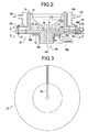
- Figure 2 provides an enlarged view of the discharge melt guide 22 enclosing the bottom 12a of the crucible 12.
- the crucible 12 comprises a solid cylindrical member, with its bottom 12a formed as an annular radial flange.
- the coolant jacket 26b comprises a double-walled cylinder that surrounds the crucible 12.
- the coolant jacket 26b is hollow for receiving the coolant 26c for cooling the crucible 12.
- the discharge melt guide 22 comprises a substantially flat base plate 28.
- the base plate 28 can be formed from an appropriate heat and electrically conductive material, such as but not limited to, copper.
- the base plate 28 comprises a circular disk that is complementary to the configuration of the crucible 12, and comprises an upper perimeter 28a with a diametrical portion that engages the crucible bottom 12a.
- the discharge guide tube 22 can form a sealed attachment to the crucible 12.
- fasteners 30, for example a plurality of circumferentially spaced apart bolts and cooperating nuts, can removably attach and seal the base plate 28 to the crucible bottom 12a.
- the fasteners 30 extend through apertures in the perimeter of the base plate 28 that are aligned with apertures disposed in a suitable annular flange around the base of the coolant jacket 26b.
- a gasket, or other such sealing element, may be provided between the base plate 28 and the crucible bottom 12a to be compressed therebetween upon assembly of the fasteners 30 that secure the base plate 28 to the bottom of crucible 12.
- the base plate 28 of the discharge guide tube 22 comprises an upper surface 28b, which together with the crucible 12, defines the reservoir 24 for receiving and pooling liquid refined melt 14a.
- the base plate 28 also comprises an external or lower surface 28c that is spaced below the upper surface 28b.
- both surfaces 28b and 28c are illustrated as substantially flat and parallel to each other. This illustrated configuration is merely exemplary and is not intended to limit the invention in any way. The scope of the invention includes other configurations of these features, such as not limited to, concave, convex, arcuate, and combinations thereof, with or without flat and parallel features.
- the base plate 28 also comprises includes a central orifice 32 (also known in the art as a "discharge guide tube orifice") formed in an extension 29 that extends to an outlet 100.
- the central orifice 32 extends generally vertically through the base plate 28 between its upper and lower surfaces, 28b and 28c respectively.
- the central orifice 32 allows refined melt 14a to be drained from the reservoir 24, for example, and in no way limiting of the invention, by at least one of gravity flow, pressure-induced flow, and vacuum-induced flow on the bottom of the refined melt 14a.
- the discharge melt guide 22 comprises a central orifice 32 that includes an interior discharge guide tube flux concentration configuration to enhance heating by concentrating electromagnetic field and electromagnetic flux in the central orifice 32, as described hereinafter.
- the base plate 28 comprises at least one slot 34 formed therein, as illustrated in Fig. 3. Each slot 34 can extend vertically through the base plate 28. Each slot 34 directs the flow of applied electromagnetic field and electromagnetic flux in the electroslag refining apparatus, as described hereinafter.
- the base plate 28 may alternatively comprise a plurality of spaced apart slots 34, for example slots that are equiangularly, circumferentially spaced from each other, and that extend radially outwardly from the orifice 32 toward the perimeter of the base plate 28.
- a plurality of equiangularly, circumferentially spaced slots 34 are illustrated in Fig. 4.
- four slots 34 are illustrated as being disposed about 90 degrees apart from each other, however, this configuration is merely exemplary of the slot configurations within the scope of the invention.
- the scope of the invention comprises any suitable number of slots 34 in the base plate 28.
- the slots 34 may also be formed using electrodischarge machining (EDM). Alternatively, other known metallurgical processes may be used to form the slots 34, and are within the scope of the invention.
- the slots 34 can be gas filled, or filled with an electrical insulation 36, such as, but not limited to, an epoxy polymer.
- the slots 34 define a plurality of arcuate segments or fingers 28d.
- the illustrated configuration (Fig. 4) shows four fingers 28d (alternatively referred to as "segments") defined between the slots 34.
- the cooling system 40 for the base plate 28 can comprise channels 40a that extend inside each of the fingers 28d for circulating a coolant 26c therethrough.
- the cooling system 40 can be provided with its own source of coolant.
- the cooling system 40 may be disposed in parallel with the cooling supply 26a, and use the coolant that cools the crucible 12. This configuration is merely exemplary of the scope of the invention and is not intended to limit the invention in any manner.
- Each finger 28d can comprise an approximate 90-degree corner.
- the cooling channels 40a in the discharge guide tube 22 may be formed by drilling cylindrical holes radially inwardly from the outer perimeter of the base plate 28. Adjacent channels 40a may be disposed therein to converge radially inwardly and intersect near the central orifice 32, thus providing supply and return paths for coolant flow.
- the cooling system 40 also includes a pair of coolant manifolds 40b and 40c, which may be integrally formed with the base plate 28.
- the manifolds 40b and 40c may be attached around the perimeter of the base plate 28, with the supply manifold 40b being disposed in communication with a channel 40a for supplying the coolant.
- the return manifold 40c may be disposed in communication with channels 40a for receiving return coolant.
- the manifolds 40b and 40c can be connected to the coolant supply 26a for circulating the coolant.
- the discharge melt guide 22 comprises an induction heater system 38.
- the induction heater system 38 is disposed proximate and below the base plate lower surface 28c for induction heating the refined melt 14a and the consumable electrode 14.
- proximate means near or close to, and is used with a meaning as understood by those of skill in the art with its conventional meaning.
- the heat, electromagnetic field, and electromagnetic flux generated by the induction heater system 38 can be transmitted to those and other elements of the electroslag refining apparatus 10 resulting in heating as desired.
- the induction heater system 38 may take any conventional configuration including, but not limited to, an annular or spiraling induction heater system configuration.
- the coils of the induction heater system 38 can be disposed coaxially about the central orifice 32 and can extend radially over the slots 34. As illustrated in Fig. 1, the induction heater system 38 can include one or more suitable power supplies 38p that provide electrical current that is sufficient for induction heating.
- the induction heating coils can comprise hollow coils that circulate a suitable coolant, such as, but not limited to, water.
- the induction heater system 38 can comprise primary coils 38a, which are generally co-axial with the central orifice 32 along the extension 29, and secondary coils 38b that are generally disposed on surface 28c of the base plate 28.
- the induction heater system 38 is disposed on the extension 29 of the discharge melt guide 22 to define a gap therebetween.
- the disposition of the induction heater system 38 on the extension 29 allows movement of induction heater system 38 in the direction of arrow 500 (Fig. 6) with the gap remaining constant.
- the constant nature of the gap allows generated heat, electromagnetic field, and electromagnetic flux from the induction heater system 38 to be substantially unaffected by movement of the induction heater system 38 in the direction of arrow 500.
- the term "substantially” is used with its normal meaning as understood by those of skill in the art.
- the primary coils 38a and secondary coils 38b of the induction heater system 38 may define independent primary and secondary coils, 38a and 38b, respectively. Alternatively, the primary coils 38a and secondary coils 38b may be connected to create an integral coil structure for the induction heater system 38.
- the primary coils 38a and secondary coils 38b may take any appropriate coil configuration and structure, such as, but not limited to, water-cooled, current-carrying conduit coils.
- the primary coils 38a and secondary coils 38b may be overlapped at at least one portion, such as but not limited to, coiled onto themselves.
- the illustrated configurations are merely exemplary of the structures within the scope of the invention, and are not intended to limit the invention in any manner.
- the primary coil 38a of the induction heater device 38p can be disposed adjacent to and surrounding the central orifice 32 for heating the refined melt 14a that is discharged therethrough.
- the primary coil 38a may also control a thickness of the corresponding skull 14b that is disposed proximate the central orifice 32.
- the secondary coils 38b can be spaced radially outwardly from the primary coil 38a, and may radially overlap (not illustrated).
- the secondary coil 38b can comprise a sufficient number of turns for sufficiently heating the refined melt 14a around and in the central orifice 32.
- the secondary coils 38b can also control a thickness of the ingot skull 14b, as described above.
- the central orifice 32 of the discharge guide tube (also known as a “discharge guide tube”) 22 comprises an internal configuration with a profile that concentrates heat, electromagnetic field, and electromagnetic flux (hereinafter “heat and electromagnetic flux” since the electromagnetic flux is produced by the electromagnetic field) to the stream of liquid melt that flows therethrough.
- heat and electromagnetic flux since the electromagnetic flux is produced by the electromagnetic field
- the central orifice 32 comprises an angled and stepped profile about a central longitudinal axis 138 of the central orifice 32.
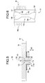
- the stepped and angled profile can be formed by an inclined (first) central orifice ramp portion 130 that extends from a first central orifice portion 131 to a reduced diameter central orifice portion 132, which defines a constriction 133, and then to another (second) inclined central orifice ramp portion 134, which in turn leads to a further (second) central orifice portion 135.
- the diameter of the second central orifice portion 132 is less that the diameter of the first central orifice portion 131.
- the ramp portion leads to a constriction 133 in the central orifice 32 at which point the flux concentration in the central orifice 32 is higher than at other portions of the central orifice 32, such as at the first central orifice portion 131.
- the configuration of the central orifice 32 at which the constriction 133 is formed can comprise any appropriate configuration that can produce the concentrations of electromagnetic field and electromagnetic flux.
- the angles for the inclined central orifice ramp portion 130 and 134 can comprise any angles that form the constriction 133.
- the lengths of the inclined central orifice ramp portions 130 and 134 can be equal. Alternatively, lengths of the inclined central orifice ramp portions 130 and 134 need not be equal. Further, the length of the second central orifice portion 132 may vary. Also, the positioning of the second central orifice portion 132, and thus the constriction, in the central orifice 32 may vary.
- the positioning of the second central orifice portion 132 and the constriction in the central orifice 32 may equi-spaced in the central orifice 32, be disposed closer to the electroslag refining apparatus 10 than an exit from the central orifice 32, or be disposed closer to the exit from the central orifice 32 than to the electroslag refining apparatus 10. Accordingly, the positioning and configuration of the features of the central orifice 32, as embodied by the invention, to produce the heat and electromagnetic flux can vary, as long as the intended purpose of the invention is accomplished.
- the central orifice 32 including the ramp portion 130 that extends from a first central orifice portion 131 to a second central orifice portion 132, may be formed by any metallurgical machining suitable process.
- the scope of the invention includes forming the central orifice 32 by a machining processes, such as, but not limited to, at least one of drilling, lathe turning, and electrodischarge machining (EDM). If drilling is used to form the central orifice 32, a drilling process provides a passage, which has a diameter that generally equal to that of the constriction 133, and larger diameters at the first central orifice portion 131 may be provided by further drilling.
- the central orifice 32 is formed to be generally perpendicular to the upper and lower surfaces, 28b and 28c respectively, of the base plate 28. Therefore, the liquid refined melt 14a can flow straight downwardly by gravity from the central orifice 32 during electroslag refining operations.
- the above-described drilling is merely exemplary of formation processes within the scope of the invention, and other formation processes can be used herein.
- the induction heating system 38 is disposed along the lower surface 28c of the base plate 28 in a generally concentric configuration to be disposed around the central orifice 32.
- the coils of the induction heating system 38 are also disposed over the radial extent of the slots 34 for transmitting electromagnetic energy into the melt 14a.
- the heat and electromagnetic flux are transmitted to the constriction 133 in the central orifice 32 in amounts sufficient to maintain the stream of refined liquid melt 14a that is flowing through the central orifice 32 in a liquidus state for continued flow through the central orifice 32. Further, the heat and electromagnetic flux can control the flow of refined liquid melt through the central orifice 32.
- the flow through the central orifice 32 can be lessened by reducing the amount of heat and electromagnetic flux that is applied to the electroslag refining apparatus 10, as embodied by the invention.
- With less electromagnetic field generating less heat there will be less concentrated electromagnetic flux at the constriction 133 in the central orifice 32.
- Less electromagnetic flux at the constriction 133 will slow flow of the liquid refined melt 14a through the central orifice 32.
- an amount of time that the liquid refined liquid melt 14a is in contact with the skull 14b increases, and with more time in contact with the skull 14b, the refined liquid melt 14a may solidify against the skull 14b.
- more skull 14b may form around the area at the central orifice 32 and restrict flow into and through the central orifice 32, thereby controlling the flow in the electroslag refining apparatus 10.
- the heat melts the skull may reach a limit that is bounded by the generated electromagnetic flux.
- the electromagnetic flux may cause a field constriction in the central orifice 32 that may limit flow.
- the configuration of the central orifice 32 and the interior discharge guide tube flux concentration configuration defines the electromagnetic flux amount at which point the electromagnetic flux will cause restriction in the central orifice 32.
- the flow of the refined melt 14a through the central orifice 32 may also be controlled, so as to be approximately equal to the melt rate of metal from the consumable electrode 14. Accordingly, a generally steady-state flow in the electroslag refining apparatus 10 can be provided.
- the induction heating of the liquid refined melt 14a through the slots 34, and cooling of the base plate 28 around the central orifice 32, can be provide a balanced flow relationship during startup and steady-state operations of the electroslag refining apparatus 10.
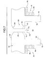
- FIG. 7 is a part-sectional illustration of another central orifice 232 within the scope of the invention.
- the central orifice 232 is formed in a base plate 128 of a discharge guide tube 22 and comprises an internal configuration with a profile that concentrates heat, electromagnetic field, and electromagnetic flux to the stream of liquid melt that flows therethrough.
- the central orifice 232 comprises an angled and stepped profile about a central longitudinal axis 138 of the central orifice 232.
- the base plate 128 comprises and is formed in a similar manner as the above-described base plate 28, however, the base plate 128 includes an extension 129 that defines a base plate chamber 150.
- the base plate chamber 150 is bounded by an upper wall 151 and side walls 152.
- the central orifice 232 extends from the electroslag refining apparatus 10 to the wall 151 of the base plate 128.
- the stepped and angled profile of the central orifice 232 can be formed by an inclined central orifice ramp portion 230 that extends from a surface 128' of the base plate 128 to a constriction 233 in the central orifice 232.
- the constriction 233 may comprise a single constriction portion 235 (solid lines in Fig.
- the constriction 233 may comprise a constriction portion 235 that extends partially down the central orifice 232 length, and widens into an inclined portion 234 (broken lines in Fig. 7) that in turn terminates at the wall 151.
- the configuration of the central orifice 232 at which the constriction 233 is formed can comprise any appropriate configuration that can produce the concentrations of electromagnetic field.
- the angles for the inclined central orifice ramp portion 230 and 234 can comprise any angles that form the constriction 233.
- the lengths of the inclined central orifice ramp portions 230 and 234 can be equal. Alternatively, lengths of the inclined central orifice ramp portions 230 and 234 need not be equal. Further, the length of the constriction portion 235 may vary. Also, the positioning of the constriction portion 235 in the central orifice 232 may vary.
- the positioning of the constriction portion 235 may be equi-spaced in the central orifice 232, be disposed closer to the electroslag refining apparatus 10 than an exit from the central orifice 232, or be disposed closer to the exit from the central orifice 232 than to the electroslag refining apparatus 10. Accordingly, the positioning and configuration of the features of the central orifice 232, as embodied by the invention, to produce the heat, electromagnetic field, and electromagnetic flux can vary, as long as the intended purpose of the invention is accomplished.
- the discharge guide tube 22, as embodied by the invention, may be used in cooperation with an electroslag refining apparatus 10, as illustrated in Fig. 1.
- the discharge guide tube 22 can be used in conjunction with any subsequent processing of the stream of liquid refined melt 14a that is discharged from the electroslag refining apparatus 10.
- atomizing structure may be provided for injecting a suitable atomizing gas from a gas supply to atomize the stream 114a of liquid refined melt 14a discharged from the central orifice 32, as embodied by the invention.
- the discharge guide tube 22, as embodied by the invention may be used in cooperation with device as set forth in US Patent No. 5,381,847 to Ashok et al.
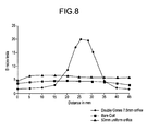
- Figure 8 is a graph of field intensity versus guide tube axial distance for a discharge melt guide, as embodied by the invention.
- the discharge guide tube that is graphed in Fig. 8 comprises a four-turn induction heater coil structure.
- the coils carry about 87mA at about 143,000 Hz.
- the generated electromagnetic field and electromagnetic flux along the axis 138 is measured with a search coil in order to determine the field in the central orifice 32.
- alternating current magnetic fields are measured for a simple coil, a straight un-constricted discharge guide tube configuration as set forth in US Patent No. 5,809,057, and a discharge guide tube configuration, as embodied by the invention.
- the discharge guide tube configuration as embodied by the invention, the discharge guide tube provides a clear enhancement of the generated electromagnetic field.
Landscapes
- Engineering & Computer Science (AREA)
- Mechanical Engineering (AREA)
- General Engineering & Computer Science (AREA)
- Manufacture And Refinement Of Metals (AREA)
- Furnace Charging Or Discharging (AREA)
- Furnace Details (AREA)
Abstract
Description
- The invention relates to induction-heated guide-tubes for pouring of liquid metal. In particular, the invention relates to pouring of superalloys during electroslag refining using a copper guide tube that concentrates flux in the liquid metal stream.
- Electroslag refining is a process used to melt and refine a wide range of alloys, including but not limited to superalloys, for removing various impurities therefrom. U.S. Pat. No. 5,160,532, issued to Benz et al., discloses an electroslag refining apparatus that is assigned to the Assignee of the present invention, General Electric. Other ESR structures are set forth in several US patents issued to the Assignee of the present invention, General Electric, including US Patent Nos. 5,310,165; 5,325,906; 5,332,197; 5,348,666; 5,366,206; 5,472,097; 5,649,992; 5,649,993, 5,683,653, 5,769,151; 5,809,057; and 5,810,066, the contents of each are incorporated herein.
- In general, an electroslag refining apparatus comprises an ingot being connected to a power supply, for example one of an alternating or direct current power supply. The ingots comprise unrefined alloys that may include various defects or impurities, which are desired to be removed during the refining process to enhance its metallurgical properties, including, but are not limited to, grain size and microstructure. The ingot forms a consumable electrode that is suitably suspended in a water-cooled crucible, which contains a slag corresponding with the alloy being refined. The slag is heated by passing an electrical current from the electrode through the slag into the crucible. The slag is maintained at a suitable high temperature for melting the lower end of the consumable electrode into an ingot melt. As the consumable electrode melts, a refining action takes place with oxide inclusions in the ingot melt being exposed to the liquid slag and dissolved therein. Liquid refined melt of the ingot melt fall through the slag by gravity, which may be augmented or diminished by additional electromagnetic forces. The liquid refined melt is collected in a liquid melt pool at the bottom of the crucible. The slag, therefore, effectively removes various impurities from the melt to effect the refining thereof. The refined melt may be extracted from the crucible by an induction-heated, segmented, water-cooled copper guide tube. The refined melt extracted from the crucible thus provides a liquid metal source for various solidification processes including, but not limited to, powder atomization, spray deposition, spray forming investment casting, melt-spinning, nucleated-casting, strip casting, and slab casting.
- In above-described electroslag refining apparatus, the crucible can be formed of copper, and is typically water-cooled to form a solid slag and/or metal skull on its surface. The solid slag or metal skull bounds the liquid slag and prevents damage to the crucible itself. The bottom of the crucible typically includes a water-cooled, cold hearth, which can be formed of copper, against which a solid skull of the refined melt forms for maintaining the purity of the collected melt at the bottom of the crucible. A discharge guide tube assembly below the hearth can also be formed of copper. The discharge guide tube assembly is often segmented and water-cooled and allows the formation of a solid skull of the refined melt for maintaining the purity of the melt as it is extracted from the crucible. The skulls can prevent contamination of the ingot melt from contact with the parent material of the crucible.
- The electroslag refining apparatus also may include a plurality of water-cooled induction heating electrical conduits that surround a discharge guide tube. The conduits inductively heat the melt and the discharge guide tube can control the discharge flow rate through the discharge guide tube. Accordingly, the thickness of the skull formed around the discharge orifice may be controlled and suitably matched with melting rates of the consumable electrode for obtaining a substantially steady state production through the discharge guide tube.
- The discharge guide tube and cold hearth of some electroslag refining apparatuses are generally structurally complex, and are generally comprise a plurality of fingers or segments, which are surrounded by the induction heating electrical conduits. These induction heating electrical conduits are often single piece units that are typically provided with a set configuration to conform with the configuration of the discharge guide tube. The configuration is provided to define a gap between the induction heating electrical conduits and the discharge guide tube. This configurations is suitable for heating the melt in and about the discharge guide tube in electroslag refining applications. However, if one or both of the induction heating electrical conduits and discharge guide tubes are moved with respect to one another, the gap therebetween changes due to the single-piece configuration of the induction heating electrical conduits. Therefore, the heating of the melt in and about the discharge guide tube in electroslag refining applications may be influenced, often detrimentally.
- Further, each of the discharge guide tube's segments may be manufactured with internal cooling passages, which adds to the complexity of the assembly and cost of manufacture. The discharge guide tube is typically integrally joined to the cold hearth with the induction heating coils surrounding its outer surface. Typically, these discharge guide tubes require numerous and complex manufacturing and machining to be formed, including specialty milling. Thus, the discharge guide tube and cold hearth are expensive to manufacture.
- The above-described electrical conduits generate an electromagnetic field, and an associated electromagnetic flux within the discharge guide tube, thus heating any material flowing therethrough. The intensity of the generated electromagnetic field and electromagnetic flux is typically related to the heating capability of the guide tube apparatus. As the electromagnetic field and electromagnetic flux intensities increase, the heating capability within the discharge guide tube increases. A high field intensity and electromagnetic flux, and resultant high heating capability in a guidte tube apparatus, is often desirable for creating an initial stream of metal, melting any undesired solid metal within the electroslag refining apparatus, and super-heating the stream flowing through the discharge guide tube.
- The electromagnetic flux intensity in the guide tube apparatus can be enhanced by providing at least one of a high applied voltage in the electrical conduits and an increased number of induction heating elements disposed about the guide tube apparatus. The configuration and structure of the guide tube apparatus can limit a number of induction heating elements. Further, the current amount is limited by the configuration and structure of the induction heating elements and an availability of electrical energy. Thus, the guide tube apparatus may be limited in its the capability to enhance the electromagnetic field and resulting electromagnetic flux intensity in the discharge guide tube.
- Accordingly, a need exists to enhance the electromagnetic field, and resulting electromagnetic flux in copper guide tube apparatuses. In particular, a need exists to enhance the electromagnetic flux concentration without significant redesign of the guide tube apparatus.
- In one aspect of the invention, a discharge guide tube comprises a central orifice that extends from a source of metal to an outlet in the discharge guide tube for directing a stream of melt therethrough; a structure that generates an electromagnetic field in the discharge guide tube; and an interior discharge guide tube flux concentration configuration that is capable of concentrating electromagnetic flux, and therefore heat, onto the stream of melt that flows through the central orifice.
- In another aspect of the invention, a guide tube structure for flux concentration in an electroslag refining apparatus is provided. The discharge guide tube comprises a base plate; an extension; a central orifice that extends from a source of metal to an outlet in the discharge guide tube for directing a stream of melt therethrough; and an interior discharge guide tube flux concentration configuration that is capable of concentrating electromagnetic flux onto the stream of melt that flows through the central orifice, the interior discharge guide tube flux concentration configuration comprising an angled and stepped profile to electromagnetic flux and heat onto the stream of melt that flows through the central orifice. The stepped and angled profile comprises a first central orifice portion; a second central orifice portion; a reduced diameter central orifice portion; a first inclined central orifice ramp portion; and a second inclined central orifice ramp portion. The first inclined central orifice ramp portion extends from the first central orifice portion to the reduced diameter central orifice portion, and the second inclined central orifice ramp portion extends from the reduced diameter central orifice portion to the second central orifice portion. The discharge guide tube further comprises an induction heater system disposed on the discharge guide tube with a gap therebetween, electromagnetic flux and heat that is concentrated onto the stream of melt that flows through the central orifice remains substantially constant with movement of the induction heater system on the discharge guide tube, the induction heater system comprises at least two induction heater coils, a first induction heater coil being disposed proximate the base plate and a second induction heater coil being disposed proximate the extension so as to form a gap between the second induction heater coil and the extension.
- The invention will now be described in greater detail, by way of example, with reference to the drawings, in which:-
- Figure 1 is a schematic illustration of an electroslag refining apparatus, as embodied by the invention;
- Figure 2 is a schematic illustration of a discharge guide tube, as embodied by the invention;
- Figure 3 is a bottom illustration of a discharge guide tube, as embodied by the invention;
- Figure 4 is a top, partial section illustration of a discharge guide tube of Fig. 2 taken along line 3-3;
- Figure 5 is a schematic, partial section illustration of a discharge guide tube, as embodied by the invention;
- Figure 6 is a schematic, partial section detailed illustration of a discharge guide tube of Fig. 1, as embodied by the invention;
- Figure 7 is a schematic, partial section detailed illustration of another discharge guide tube, as embodied by the invention; and
- Figure 8 is a graph of field intensity versus cold-walled induction guide tube axial tube distance.
-
- The guide tube structure, as embodied by the invention, concentrates flux, electromagnetic fields, and resultant heating for various metal refining and discharge apparatus and process, as appropriate. These metal refining and discharge apparatuses and processes comprise, but are not limited to, an electroslag refining apparatuses and processes, vacuum-induction metal apparatuses and processes, induction melt apparatuses and processes, electron beam cold hearth apparatuses and processes, plasma arc apparatuses and processes, vacuum arc remelting apparatuses and processes, and others. The following description will refer to electroslag refining apparatuses and processes as exemplary refining apparatuses and processes, however this is merely for description purposes, and other metal refining apparatuses and processes are within the scope of the invention.
- An
electroslag refining apparatus 10 is schematically illustrated in Figs. 1 and 2. Theelectroslag refining apparatus 10 comprises acylindrical crucible 12 in which an ingot 14 (also known in the art as a "consumable electrode"), which is to undergo electroslag refining, is suspended. Afeed device 16 is provided for feeding theingot 14 into thecrucible 12 at a suitable feed rate, as known in the art. Thefeed device 16 includes, but is not limited to, a suitable drive motor andtransmission 16a, that rotate ascrew 16b that in turn lowers, or translates downwardly, asupport bar 16c that is fixedly joined at one end to the top of theconsumable electrode 14. Although the illustrated configuration of theelectroslag refining apparatus 10 illustrates aconsumable electrode 14 as the source of metal to be electroslag refined, the scope of the invention comprises other suitable sources, such as but not limited to a powder source or a liquid metal source. - The
consumable electrode 14 comprises a suitable alloy to be electroslag refined, in which the alloy comprises nickel-, iron-, iron-nickel-, or cobalt-based alloy or superalloy. Aslag 18 is provided inside thecrucible 12. Theslag 18 comprises any suitable composition for refining theconsumable electrode 14. Aheater device 20 is provided for melting the tip of theconsumable electrode 14 as theconsumable electrode 14 is fed into thecrucible 12. Theheater device 20 includes a suitable electricalcurrent power supply 20a that is electrically connected to theconsumable electrode 14. Theheater supply 20a is connected to theconsumable electrode 14 through the supportingbar 16c, for example by anelectrical lead 20b. Electrical current is carried through theconsumable electrode 14, and through theliquid slag 18 to thecrucible 12. Therefore, theslag 18 is resistively heated to a temperature that is suitable to melt the bottom end of theconsumable electrode 14. Although the illustrated embodiment sets forth aconsumable electrode 14 as the source of electrical current, the scope of the invention comprises other suitable sources of current, including, but not limited to, an unconsumed electrode. - A copper
discharge melt guide 22, as embodied by the invention, is removably attached to a bottom 12a of thecrucible 12. Thedischarge melt guide 22 comprises acentral orifice 32 that includes a configuration to concentrate heating, electromagnetic field, and electromagnetic flux in thecentral orifice 32, as described hereinafter. Thedischarge melt guide 22 encloses the bottom of thecrucible 12. An electrical path can be provided between thepower supply 20a by anelectrical lead 20c. Theslag 18 is heated by thepower supply 20a, and this heating causes a bottom tip of theconsumable electrode 14 to be correspondingly heated and melted. Liquid refined melt of molten metal, or simply liquidrefined melt 14a from theconsumable electrode 14 is formed. The liquidrefined melt 14a falls through theslag 18 and collects in a liquid metal pool orreservoir 24, which is disposed at the bottom of thecrucible 12. - The
electroslag refining apparatus 10, as embodied by the invention, comprises a cooling system that cools thecrucible 12 during operation of theelectroslag refining apparatus 10. Thecooling system 26 can comprise acoolant supply 26a that is effective for pumping acoolant 26c, such as, but not limited to water, through a cooperating coolingjacket 26b that is disposed around thecrucible 12. Thecrucible 12 andcooling jacket 26b may be an integral assembly. Alternatively, thecrucible 12 andcooling jacket 26b may be discrete components connected together in thermal cooperation. The coolingjacket 26b includes suitable channels or conduits that extend therethrough, andcoolant 26c is circulated for removing heat from thecrucible 12 during operation of theelectroslag refining apparatus 10. - A
solid slag skull 18a can form inside thecrucible 12 around theliquid slag 18. Thesolid slag skull 18a can isolate thecrucible 12 from theliquid slag 18 and the metal that can fall through theelectroslag refining apparatus 10. Electroslag refining of theconsumable electrode 14 occurs as the metal liquid refinedmelt 14a are exposed to theslag 18. Theslag 18 dissolves inclusions, such as but not limited to oxide inclusions and nitrogen inclusions, from the liquidrefined melt 14a. - The
crucible 12, which typically comprises copper, is isolated from the refining process by thesolid slag skull 18a. Therefore, thecrucible 12 does not contaminate theingot melt 14a. The refined melt collects in thereservoir 24 at the bottom of thecrucible 12. Theingot skull 14b isolates the refined melt from thecrucible 12 and prevents contamination of the melt by thecrucible 12. During operation, theliquid slag 18 floats atop the pool of refined melt that is collected above thedischarge melt guide 22. - The
discharge melt guide 22, as embodied by the invention, is illustrated in Fig. 2, is configured to generate enhanced heat, electromagnetic field, and electromagnetic flux intensity and concentration when compared to conventional melt guides, such as in US Patent No. 5,809,057, to Benz, which is assigned to the Assignee of the instant invention and fully incorporated herein. It has been determined that the amount of induction heating in the discharge guide tube, as embodied by the invention, is generally proportional to the square of the applied electromagnetic field, and that with the interior discharge guide tube flux concentration configuration, as described hereinafter, provides at least one of heat, electromagnetic field, and electromagnetic flux in a substantially constant levels, with changes in coil position. - Figure 2 provides an enlarged view of the discharge melt guide 22 enclosing the bottom 12a of the
crucible 12. In Fig. 2, thecrucible 12 comprises a solid cylindrical member, with its bottom 12a formed as an annular radial flange. Thecoolant jacket 26b comprises a double-walled cylinder that surrounds thecrucible 12. Thecoolant jacket 26b is hollow for receiving thecoolant 26c for cooling thecrucible 12. - The
discharge melt guide 22, as embodied by the invention, comprises a substantiallyflat base plate 28. Thebase plate 28 can be formed from an appropriate heat and electrically conductive material, such as but not limited to, copper. Thebase plate 28 comprises a circular disk that is complementary to the configuration of thecrucible 12, and comprises anupper perimeter 28a with a diametrical portion that engages thecrucible bottom 12a. Thus, thedischarge guide tube 22 can form a sealed attachment to thecrucible 12. Also,fasteners 30, for example a plurality of circumferentially spaced apart bolts and cooperating nuts, can removably attach and seal thebase plate 28 to thecrucible bottom 12a. In Fig. 2, thefasteners 30 extend through apertures in the perimeter of thebase plate 28 that are aligned with apertures disposed in a suitable annular flange around the base of thecoolant jacket 26b. A gasket, or other such sealing element, may be provided between thebase plate 28 and thecrucible bottom 12a to be compressed therebetween upon assembly of thefasteners 30 that secure thebase plate 28 to the bottom ofcrucible 12. - The
base plate 28 of thedischarge guide tube 22 comprises anupper surface 28b, which together with thecrucible 12, defines thereservoir 24 for receiving and pooling liquidrefined melt 14a. Thebase plate 28 also comprises an external orlower surface 28c that is spaced below theupper surface 28b. In Fig. 2, bothsurfaces - The
base plate 28 also comprises includes a central orifice 32 (also known in the art as a "discharge guide tube orifice") formed in anextension 29 that extends to anoutlet 100. Thecentral orifice 32 extends generally vertically through thebase plate 28 between its upper and lower surfaces, 28b and 28c respectively. Thecentral orifice 32 allows refinedmelt 14a to be drained from thereservoir 24, for example, and in no way limiting of the invention, by at least one of gravity flow, pressure-induced flow, and vacuum-induced flow on the bottom of therefined melt 14a. Thedischarge melt guide 22 comprises acentral orifice 32 that includes an interior discharge guide tube flux concentration configuration to enhance heating by concentrating electromagnetic field and electromagnetic flux in thecentral orifice 32, as described hereinafter. - The
base plate 28 comprises at least oneslot 34 formed therein, as illustrated in Fig. 3. Eachslot 34 can extend vertically through thebase plate 28. Eachslot 34 directs the flow of applied electromagnetic field and electromagnetic flux in the electroslag refining apparatus, as described hereinafter. Thebase plate 28 may alternatively comprise a plurality of spaced apartslots 34, for example slots that are equiangularly, circumferentially spaced from each other, and that extend radially outwardly from theorifice 32 toward the perimeter of thebase plate 28. - A plurality of equiangularly, circumferentially spaced
slots 34 are illustrated in Fig. 4. In Fig. 4, fourslots 34 are illustrated as being disposed about 90 degrees apart from each other, however, this configuration is merely exemplary of the slot configurations within the scope of the invention. The scope of the invention comprises any suitable number ofslots 34 in thebase plate 28. Theslots 34 may also be formed using electrodischarge machining (EDM). Alternatively, other known metallurgical processes may be used to form theslots 34, and are within the scope of the invention. Theslots 34 can be gas filled, or filled with anelectrical insulation 36, such as, but not limited to, an epoxy polymer. - The
slots 34 define a plurality of arcuate segments orfingers 28d. The illustrated configuration (Fig. 4) shows fourfingers 28d (alternatively referred to as "segments") defined between theslots 34. Thecooling system 40 for thebase plate 28 can comprisechannels 40a that extend inside each of thefingers 28d for circulating acoolant 26c therethrough. Thecooling system 40 can be provided with its own source of coolant. Alternatively, thecooling system 40 may be disposed in parallel with thecooling supply 26a, and use the coolant that cools thecrucible 12. This configuration is merely exemplary of the scope of the invention and is not intended to limit the invention in any manner. Eachfinger 28d can comprise an approximate 90-degree corner. Thecooling channels 40a in thedischarge guide tube 22 may be formed by drilling cylindrical holes radially inwardly from the outer perimeter of thebase plate 28.Adjacent channels 40a may be disposed therein to converge radially inwardly and intersect near thecentral orifice 32, thus providing supply and return paths for coolant flow. - In the illustrated exemplary embodiment of Figs. 2 and 4, the
cooling system 40 also includes a pair ofcoolant manifolds base plate 28. Alternatively, themanifolds base plate 28, with thesupply manifold 40b being disposed in communication with achannel 40a for supplying the coolant. Thereturn manifold 40c may be disposed in communication withchannels 40a for receiving return coolant. Themanifolds coolant supply 26a for circulating the coolant. - The
discharge melt guide 22 comprises aninduction heater system 38. Theinduction heater system 38 is disposed proximate and below the base platelower surface 28c for induction heating therefined melt 14a and theconsumable electrode 14. The term "proximate" means near or close to, and is used with a meaning as understood by those of skill in the art with its conventional meaning. The heat, electromagnetic field, and electromagnetic flux generated by theinduction heater system 38 can be transmitted to those and other elements of theelectroslag refining apparatus 10 resulting in heating as desired. Theinduction heater system 38 may take any conventional configuration including, but not limited to, an annular or spiraling induction heater system configuration. - The coils of the
induction heater system 38 can be disposed coaxially about thecentral orifice 32 and can extend radially over theslots 34. As illustrated in Fig. 1, theinduction heater system 38 can include one or moresuitable power supplies 38p that provide electrical current that is sufficient for induction heating. The induction heating coils can comprise hollow coils that circulate a suitable coolant, such as, but not limited to, water. - The
induction heater system 38 can compriseprimary coils 38a, which are generally co-axial with thecentral orifice 32 along theextension 29, andsecondary coils 38b that are generally disposed onsurface 28c of thebase plate 28. Theinduction heater system 38 is disposed on theextension 29 of the discharge melt guide 22 to define a gap therebetween. The disposition of theinduction heater system 38 on theextension 29 allows movement ofinduction heater system 38 in the direction of arrow 500 (Fig. 6) with the gap remaining constant. The constant nature of the gap allows generated heat, electromagnetic field, and electromagnetic flux from theinduction heater system 38 to be substantially unaffected by movement of theinduction heater system 38 in the direction ofarrow 500. The term "substantially" is used with its normal meaning as understood by those of skill in the art. - The
primary coils 38a andsecondary coils 38b of theinduction heater system 38 may define independent primary and secondary coils, 38a and 38b, respectively. Alternatively, theprimary coils 38a andsecondary coils 38b may be connected to create an integral coil structure for theinduction heater system 38. Theprimary coils 38a andsecondary coils 38b may take any appropriate coil configuration and structure, such as, but not limited to, water-cooled, current-carrying conduit coils. For example, theprimary coils 38a andsecondary coils 38b may be overlapped at at least one portion, such as but not limited to, coiled onto themselves. The illustrated configurations are merely exemplary of the structures within the scope of the invention, and are not intended to limit the invention in any manner. - The
primary coil 38a of theinduction heater device 38p can be disposed adjacent to and surrounding thecentral orifice 32 for heating therefined melt 14a that is discharged therethrough. Theprimary coil 38a may also control a thickness of thecorresponding skull 14b that is disposed proximate thecentral orifice 32. Thesecondary coils 38b can be spaced radially outwardly from theprimary coil 38a, and may radially overlap (not illustrated). Thesecondary coil 38b can comprise a sufficient number of turns for sufficiently heating therefined melt 14a around and in thecentral orifice 32. Thesecondary coils 38b can also control a thickness of theingot skull 14b, as described above. - The
central orifice 32 of the discharge guide tube (also known as a "discharge guide tube") 22 comprises an internal configuration with a profile that concentrates heat, electromagnetic field, and electromagnetic flux (hereinafter "heat and electromagnetic flux" since the electromagnetic flux is produced by the electromagnetic field) to the stream of liquid melt that flows therethrough. As illustrated in Fig. 2 and in detail in Figs. 5 and 6, thecentral orifice 32 comprises an angled and stepped profile about a centrallongitudinal axis 138 of thecentral orifice 32. The stepped and angled profile can be formed by an inclined (first) centralorifice ramp portion 130 that extends from a firstcentral orifice portion 131 to a reduced diametercentral orifice portion 132, which defines aconstriction 133, and then to another (second) inclined centralorifice ramp portion 134, which in turn leads to a further (second)central orifice portion 135. The diameter of the secondcentral orifice portion 132 is less that the diameter of the firstcentral orifice portion 131. In other words, the ramp portion leads to aconstriction 133 in thecentral orifice 32 at which point the flux concentration in thecentral orifice 32 is higher than at other portions of thecentral orifice 32, such as at the firstcentral orifice portion 131. - The configuration of the
central orifice 32 at which theconstriction 133 is formed can comprise any appropriate configuration that can produce the concentrations of electromagnetic field and electromagnetic flux. The angles for the inclined centralorifice ramp portion constriction 133. The lengths of the inclined centralorifice ramp portions orifice ramp portions central orifice portion 132 may vary. Also, the positioning of the secondcentral orifice portion 132, and thus the constriction, in thecentral orifice 32 may vary. For example, the positioning of the secondcentral orifice portion 132 and the constriction in thecentral orifice 32 may equi-spaced in thecentral orifice 32, be disposed closer to theelectroslag refining apparatus 10 than an exit from thecentral orifice 32, or be disposed closer to the exit from thecentral orifice 32 than to theelectroslag refining apparatus 10. Accordingly, the positioning and configuration of the features of thecentral orifice 32, as embodied by the invention, to produce the heat and electromagnetic flux can vary, as long as the intended purpose of the invention is accomplished. - The
central orifice 32, including theramp portion 130 that extends from a firstcentral orifice portion 131 to a secondcentral orifice portion 132, may be formed by any metallurgical machining suitable process. The scope of the invention includes forming thecentral orifice 32 by a machining processes, such as, but not limited to, at least one of drilling, lathe turning, and electrodischarge machining (EDM). If drilling is used to form thecentral orifice 32, a drilling process provides a passage, which has a diameter that generally equal to that of theconstriction 133, and larger diameters at the firstcentral orifice portion 131 may be provided by further drilling. Thus, thecentral orifice 32 is formed to be generally perpendicular to the upper and lower surfaces, 28b and 28c respectively, of thebase plate 28. Therefore, the liquidrefined melt 14a can flow straight downwardly by gravity from thecentral orifice 32 during electroslag refining operations. The above-described drilling is merely exemplary of formation processes within the scope of the invention, and other formation processes can be used herein. - The
induction heating system 38 is disposed along thelower surface 28c of thebase plate 28 in a generally concentric configuration to be disposed around thecentral orifice 32. The coils of theinduction heating system 38 are also disposed over the radial extent of theslots 34 for transmitting electromagnetic energy into themelt 14a. The heat and electromagnetic flux are transmitted to theconstriction 133 in thecentral orifice 32 in amounts sufficient to maintain the stream of refinedliquid melt 14a that is flowing through thecentral orifice 32 in a liquidus state for continued flow through thecentral orifice 32. Further, the heat and electromagnetic flux can control the flow of refined liquid melt through thecentral orifice 32. For example, if higher heat and electromagnetic flux is applied to theelectroslag refining apparatus 10, more refinedliquid melt 14a will remain in a liquidus state, and less liquidrefined melt 14a will solidify into theskull 14b. Further, some of theskull 14b proximate thecentral orifice 32 will melt, by the application of the heat and electromagnetic flux, so restrictions around thecentral orifice 32 will be reduced. Thus, flow through thecentral orifice 32 will be facilitated, andless skull 14b will be formed. - Conversely, the flow through the
central orifice 32 can be lessened by reducing the amount of heat and electromagnetic flux that is applied to theelectroslag refining apparatus 10, as embodied by the invention. With less electromagnetic field generating less heat, there will be less concentrated electromagnetic flux at theconstriction 133 in thecentral orifice 32. Less electromagnetic flux at theconstriction 133 will slow flow of the liquidrefined melt 14a through thecentral orifice 32. Thus, an amount of time that the liquid refinedliquid melt 14a is in contact with theskull 14b increases, and with more time in contact with theskull 14b, therefined liquid melt 14a may solidify against theskull 14b. Accordingly,more skull 14b may form around the area at thecentral orifice 32 and restrict flow into and through thecentral orifice 32, thereby controlling the flow in theelectroslag refining apparatus 10. The heat melts the skull may reach a limit that is bounded by the generated electromagnetic flux. At a point in the generation of the heat, the electromagnetic flux may cause a field constriction in thecentral orifice 32 that may limit flow. The configuration of thecentral orifice 32 and the interior discharge guide tube flux concentration configuration defines the electromagnetic flux amount at which point the electromagnetic flux will cause restriction in thecentral orifice 32. Thus, further control on the flow through thecentral orifice 32 can be realized. - For example, and in no way limiting of the invention, the flow of the
refined melt 14a through thecentral orifice 32 may also be controlled, so as to be approximately equal to the melt rate of metal from theconsumable electrode 14. Accordingly, a generally steady-state flow in theelectroslag refining apparatus 10 can be provided. The induction heating of the liquidrefined melt 14a through theslots 34, and cooling of thebase plate 28 around thecentral orifice 32, can be provide a balanced flow relationship during startup and steady-state operations of theelectroslag refining apparatus 10. - Figure 7 is a part-sectional illustration of another
central orifice 232 within the scope of the invention. In Fig. 7, similar reference characters that are used in the above figures are used to reference like features. Thecentral orifice 232 is formed in abase plate 128 of adischarge guide tube 22 and comprises an internal configuration with a profile that concentrates heat, electromagnetic field, and electromagnetic flux to the stream of liquid melt that flows therethrough. Thecentral orifice 232 comprises an angled and stepped profile about a centrallongitudinal axis 138 of thecentral orifice 232. - The
base plate 128 comprises and is formed in a similar manner as the above-describedbase plate 28, however, thebase plate 128 includes anextension 129 that defines abase plate chamber 150. Thebase plate chamber 150 is bounded by anupper wall 151 andside walls 152. Thecentral orifice 232 extends from theelectroslag refining apparatus 10 to thewall 151 of thebase plate 128. The stepped and angled profile of thecentral orifice 232 can be formed by an inclined centralorifice ramp portion 230 that extends from a surface 128' of thebase plate 128 to aconstriction 233 in thecentral orifice 232. Theconstriction 233 may comprise a single constriction portion 235 (solid lines in Fig. 7) that extends over the entirecentral orifice 232 length and may terminate at thewall 151. Thus, thestream 114a flows into thechamber 150. Alternatively, theconstriction 233 may comprise aconstriction portion 235 that extends partially down thecentral orifice 232 length, and widens into an inclined portion 234 (broken lines in Fig. 7) that in turn terminates at thewall 151. - The configuration of the
central orifice 232 at which theconstriction 233 is formed can comprise any appropriate configuration that can produce the concentrations of electromagnetic field. The angles for the inclined centralorifice ramp portion constriction 233. The lengths of the inclined centralorifice ramp portions orifice ramp portions constriction portion 235 may vary. Also, the positioning of theconstriction portion 235 in thecentral orifice 232 may vary. For example, the positioning of theconstriction portion 235 may be equi-spaced in thecentral orifice 232, be disposed closer to theelectroslag refining apparatus 10 than an exit from thecentral orifice 232, or be disposed closer to the exit from thecentral orifice 232 than to theelectroslag refining apparatus 10. Accordingly, the positioning and configuration of the features of thecentral orifice 232, as embodied by the invention, to produce the heat, electromagnetic field, and electromagnetic flux can vary, as long as the intended purpose of the invention is accomplished. - The
discharge guide tube 22, as embodied by the invention, may be used in cooperation with anelectroslag refining apparatus 10, as illustrated in Fig. 1. Thedischarge guide tube 22 can be used in conjunction with any subsequent processing of the stream of liquidrefined melt 14a that is discharged from theelectroslag refining apparatus 10. For example, and in no way limiting of the invention, atomizing structure may be provided for injecting a suitable atomizing gas from a gas supply to atomize thestream 114a of liquidrefined melt 14a discharged from thecentral orifice 32, as embodied by the invention. Alternatively, thedischarge guide tube 22, as embodied by the invention, may be used in cooperation with device as set forth in US Patent No. 5,381,847 to Ashok et al. - Figure 8 is a graph of field intensity versus guide tube axial distance for a discharge melt guide, as embodied by the invention. The discharge guide tube that is graphed in Fig. 8 comprises a four-turn induction heater coil structure. The coils carry about 87mA at about 143,000 Hz. The generated electromagnetic field and electromagnetic flux along the
axis 138 is measured with a search coil in order to determine the field in thecentral orifice 32. In the figure, alternating current magnetic fields are measured for a simple coil, a straight un-constricted discharge guide tube configuration as set forth in US Patent No. 5,809,057, and a discharge guide tube configuration, as embodied by the invention. As illustrated in Fig. 8, the discharge guide tube configuration, as embodied by the invention, the discharge guide tube provides a clear enhancement of the generated electromagnetic field. - For the sake of good order, various aspects of the invention are set out in the following clauses:-
- 1. A discharge guide tube for a metal refining or melting apparatus, the
discharge guide tube comprising:
- a central orifice that extends from a source of metal to an outlet in the discharge guide tube for directing a stream of melt therethrough;
- a structure that generates an electromagnetic field in the discharge guide tube; and
- an interior discharge guide tube flux concentration configuration that is capable of concentrating electromagnetic flux resulting from the generated electromagnetic field onto the stream of melt that flows through the central orifice, resulting in heating the stream, and the electromagnetic field being applied at a substantially constant level.
- 2. A discharge guide tube according to clause 1, wherein the structure comprises at least one slot formed in the discharge guide tube, the at least one slot being capable of directing an electromagnetic field in the discharge guide tube.
- 3. A discharge guide tube according to clause 1, wherein the interior discharge guide tube flux concentration configuration comprises an angled and stepped profile to concentrate at least one of heat, electromagnetic field, and electromagnetic field onto the stream of melt that flows through the central orifice.
- 4. A discharge guide tube according to
clause 3, wherein the angled and stepped profile is disposed about a central longitudinal axis of the central orifice. - 5. A discharge guide tube according to clause 4, wherein the stepped
and angled profile comprises
- a first central orifice portion;
- a second central orifice portion;
- a reduced diameter central orifice portion;
- a first inclined central orifice ramp portion; and
- a second inclined central orifice ramp portion; wherein the first inclined central orifice ramp portion extends from the first central orifice portion to the reduced diameter central orifice portion, and the second inclined central orifice ramp portion extends from the reduced diameter central orifice portion to the second central orifice portion.
- 6. A discharge guide tube according to
clause 5, wherein diameter of the reduced diameter central orifice portion is less that the diameter of each of the first central orifice portion and the second central orifice portion. - 7. A discharge guide tube according to
clause 5, wherein the diameters of the first central orifice portion and the second central orifice portion are equal. - 8. A discharge guide tube according to
clause 5, wherein the diameters of the first central orifice portion and the second central orifice portion are unequal. - 9. A discharge guide tube according to
clause 5, wherein the lengths of the first central orifice portion and the second central orifice portion are equal. - 10. A discharge guide tube according to
clause 5, wherein the lengths of the first central orifice portion and the second central orifice portion are unequal. - 11. A discharge guide tube according to
clause 5, wherein the lengths of the first inclined central orifice ramp portion and the second inclined central orifice ramp portion are equal. - 12. A discharge guide tube according to
clause 5, wherein the lengths of the first inclined central orifice ramp portion and the second inclined central orifice ramp portion are unequal. - 13. A discharge guide tube according to
clause 5, wherein each of the first inclined central orifice ramp portion and the second inclined central orifice ramp portion define angles with the first central orifice portion and the second central orifice portions, respectively, the angles being equal. - 14. A discharge guide tube according to
clause 5, wherein each of the first inclined central orifice ramp portion and the second inclined central orifice ramp portion define angles with the first central orifice portion and the second central orifice portions, respectively, the angles being unequal. - 15. A discharge guide tube according to clause 1, further comprising an induction heater system disposed on the discharge guide tube with a gap therebetween.
- 16. A discharge guide tube according to
clause 15, wherein the at least one of the heat, electromagnetic field, and electromagnetic flux that is concentrated onto the stream of melt that flows through the central orifice remains substantially constant with movement of the induction heater system on the discharge guide tube. - 17. A discharge guide tube according to clause 1, wherein the discharge guide tube comprises a base plate and an extension, the central orifice originating in the base plate and extending through the extension.
- 18. A discharge guide tube according to clause 17, further comprising an induction heater system, the induction heater system being disposed about the extension and the central orifice.
- 19. A discharge guide tube according to clause 17, wherein the induction heater system comprises at least two induction heater coils, a first induction heater coil being disposed proximate the base plate and a second induction heater coil being disposed proximate the extension so as to form a gap between the second induction heater coil and the extension.
- 20. A discharge guide tube according to clause 1, wherein the metal refining apparatus comprises an electroslag refining apparatus.
- 21. A discharge guide tube according to
clause 20, wherein the electroslag refining apparatus further comprises a cold-walled induction guide tube, and the cold-walled induction guide tube comprises the discharge guide tube. - 22. A discharge guide tube for a cold-walled induction guide tube and an
electroslag refining apparatus, the discharge guide tube comprising:
- a base plate;
- an extension;
- a central orifice that extends from a source of metal to an outlet in the discharge guide tube for directing a stream of melt therethrough;
- a structure that generates an electromagnetic field in the discharge guide tube, the electromagnetic field being applied at a substantially constant level; and
- an interior discharge guide tube flux concentration configuration that is
capable of concentrating at least one of heat, electromagnetic field, and
electromagnetic flux onto the stream of melt that flows through the central
orifice, the interior discharge guide tube flux concentration configuration
comprising an angled and stepped profile to concentrate at least one of heat,
electromagnetic field, and electromagnetic flux onto the stream of melt that
flows through the central orifice, the stepped and angled profile comprises:
- a first central orifice portion;
- a second central orifice portion;
- a reduced diameter central orifice portion;
- a first inclined central orifice ramp portion; and
- a second inclined central orifice ramp portion;
- the first inclined central orifice ramp portion extends from the first central orifice portion to the reduced diameter central orifice portion, and the second inclined central orifice ramp portion extends from the reduced diameter central orifice portion to the second central orifice portion,
- the discharge guide tube further comprising an induction heater system disposed on the discharge guide tube with a gap therebetween, the at least one of the heat, electromagnetic field, and electromagnetic flux that is concentrated onto the stream of melt that flows through the central orifice remains substantially constant with movement of the induction heater system on the discharge guide tube, the induction heater system comprises at least two induction heater coils, a first induction heater coil being disposed proximate the base plate and a second induction heater coil being disposed proximate the extension so as to form a gap between the second induction heater coil and the extension.
- 23. A discharge guide tube according to
clause 22, wherein diameter of the reduced diameter central orifice portion is less that the diameter of each of the first central orifice portion and the second central orifice portion. - 24. A discharge guide tube according to
clause 22, wherein the diameters of the first central orifice portion and the second central orifice portion are equal. - 25. A discharge guide tube according to
clause 22, wherein the diameters of the first central orifice portion and the second central orifice portion are unequal. - 26. A discharge guide tube according to
clause 22, wherein the lengths of the first central orifice portion and the second central orifice portion are equal. - 27. A discharge guide tube according to
clause 22, wherein the lengths of the first central orifice portion and the second central orifice portion are unequal. - 28. A discharge guide tube according to
clause 22, wherein the lengths of the first inclined central orifice ramp portion and the second inclined central orifice ramp portion are equal. - 29. A discharge guide tube according to
clause 22, wherein the lengths of the first inclined central orifice ramp portion and the second inclined central orifice ramp portion are unequal. - 30. A discharge guide tube according to
clause 22, wherein each of the first inclined central orifice ramp portion and the second inclined central orifice ramp portion define angles with the first central orifice portion and the second central orifice portions, respectively, the angles being equal. - 31. A discharge guide tube according to
clause 22, wherein each of the first inclined central orifice ramp portion and the second inclined central orifice ramp portion define angles with the first central orifice portion and the second central orifice portions, respectively, the angles being unequal. - 32. A method for refining metal, the method comprising passing metal through the discharge guide tube of clause 1.
- 33. A method for refining metal, the method comprising passing metal
through the discharge guide tube of
clause 22. -
Claims (10)
- A discharge guide tube for a metal refining or melting apparatus, the discharge guide tube comprising:a central orifice that extends from a source of metal to an outlet in the discharge guide tube for directing a stream of melt therethrough;a structure that generates an electromagnetic field in the discharge guide tube; andan interior discharge guide tube flux concentration configuration that is capable of concentrating electromagnetic flux resulting from the generated electromagnetic field onto the stream of melt that flows through the central orifice, resulting in heating the stream, and the electromagnetic field being applied at a substantially constant level.
- A discharge guide tube according to claim 1, wherein the structure comprises at least one slot formed in the discharge guide tube, the at least one slot being capable of directing an electromagnetic field in the discharge guide tube.
- A discharge guide tube according to claim 1 or 2, wherein the interior discharge guide tube flux concentration configuration comprises an angled and stepped profile to concentrate at least one of heat, electromagnetic field, and electromagnetic field onto the stream of melt that flows through the central orifice.
- A discharge guide tube according to claim 3, wherein the angled and stepped profile is disposed about a central longitudinal axis of the central orifice.
- A discharge guide tube according to claim 4, wherein the stepped and angled profile comprisesa first central orifice portion;a second central orifice portion;a reduced diameter central orifice portion;a first inclined central orifice ramp portion; anda second inclined central orifice ramp portion;wherein the first inclined central orifice ramp portion extends from the first central orifice portion to the reduced diameter central orifice portion, and the second inclined central orifice ramp portion extends from the reduced diameter central orifice portion to the second central orifice portion.
- A discharge guide tube for a cold-walled induction guide tube and an electroslag refining apparatus, the discharge guide tube comprising:a base plate;an extension;a central orifice that extends from a source of metal to an outlet in the discharge guide tube for directing a stream of melt therethrough;a structure that generates an electromagnetic field in the discharge guide tube, the electromagnetic field being applied at a substantially constant level; andan interior discharge guide tube flux concentration configuration that is capable of concentrating at least one of heat, electromagnetic field, and electromagnetic flux onto the stream of melt that flows through the central orifice, the interior discharge guide tube flux concentration configuration comprising an angled and stepped profile to concentrate at least one of heat, electromagnetic field, and electromagnetic flux onto the stream of melt that flows through the central orifice, the stepped and angled profile comprises:a first central orifice portion;a second central orifice portion;a reduced diameter central orifice portion;a first inclined central orifice ramp portion; anda second inclined central orifice ramp portion;the first inclined central orifice ramp portion extends from the first central orifice portion to the reduced diameter central orifice portion, and the second inclined central orifice ramp portion extends from the reduced diameter central orifice portion to the second central orifice portion,the discharge guide tube further comprising an induction heater system disposed on the discharge guide tube with a gap therebetween, the at least one of the heat, electromagnetic field, and electromagnetic flux that is concentrated onto the stream of melt that flows through the central orifice remains substantially constant with movement of the induction heater system on the discharge guide tube, the induction heater system comprises at least two induction heater coils, a first induction heater coil being disposed proximate the base plate and a second induction heater coil being disposed proximate the extension so as to form a gap between the second induction heater coil and the extension.
- A discharge guide tube according to claim 6, wherein diameter of the reduced diameter central orifice portion is less that the diameter of each of the first central orifice portion and the second central orifice portion.
- A discharge guide tube according to claim 6 or 7, wherein the diameters of the first central orifice portion and the second central orifice portion are equal.
- A discharge guide tube according to claim 6 or 7, wherein the diameters of the first central orifice portion and the second central orifice portion are unequal.
- A discharge guide tube according to claim 6 or 7, wherein the lengths of the first central orifice portion and the second central orifice portion are equal.
Applications Claiming Priority (2)
| Application Number | Priority Date | Filing Date | Title |
|---|---|---|---|
| US09/474,421 US6219372B1 (en) | 1999-12-29 | 1999-12-29 | Guide tube structure for flux concentration |
| US474421 | 1999-12-29 |
Publications (2)
| Publication Number | Publication Date |
|---|---|
| EP1112793A2 true EP1112793A2 (en) | 2001-07-04 |
| EP1112793A3 EP1112793A3 (en) | 2003-09-10 |
Family
ID=23883459
Family Applications (1)
| Application Number | Title | Priority Date | Filing Date |
|---|---|---|---|
| EP00311609A Ceased EP1112793A3 (en) | 1999-12-29 | 2000-12-22 | Guide tube structure for flux concentration |
Country Status (3)
| Country | Link |
|---|---|
| US (1) | US6219372B1 (en) |
| EP (1) | EP1112793A3 (en) |
| JP (1) | JP2001241858A (en) |
Families Citing this family (6)
| Publication number | Priority date | Publication date | Assignee | Title |
|---|---|---|---|---|
| US6358297B1 (en) * | 1999-12-29 | 2002-03-19 | General Electric Company | Method for controlling flux concentration in guide tubes |
| US6436336B1 (en) * | 2001-06-27 | 2002-08-20 | General Electric Company | Replaceable drain electroslag guide |
| US6993061B2 (en) * | 2003-11-07 | 2006-01-31 | Battelle Energy Alliance, Llc | Operating an induction melter apparatus |
| KR101218923B1 (en) * | 2010-09-15 | 2013-01-04 | 한국수력원자력 주식회사 | Cold Crucible Induction Melter Using United Inductor and Crucible |
| US20160332232A1 (en) * | 2015-05-14 | 2016-11-17 | Ati Properties, Inc. | Methods and apparatuses for producing metallic powder material |
| US10383179B2 (en) * | 2016-12-06 | 2019-08-13 | Metal Industries Research & Development Centre | Crucible device with temperature control design and temperature control method therefor |
Citations (1)
| Publication number | Priority date | Publication date | Assignee | Title |
|---|---|---|---|---|
| EP0874206A1 (en) * | 1997-04-23 | 1998-10-28 | Shinko Electric Co. Ltd. | Induction heating furnace and bottom tapping mechanism thereof |
Family Cites Families (19)
| Publication number | Priority date | Publication date | Assignee | Title |
|---|---|---|---|---|
| GB1271493A (en) * | 1968-05-09 | 1972-04-19 | Stanelco Thermatron Ltd | Improved treatment process |
| JPH02170903A (en) * | 1988-09-07 | 1990-07-02 | Daido Steel Co Ltd | Metal powder manufacturing equipment |
| US5160532A (en) | 1991-10-21 | 1992-11-03 | General Electric Company | Direct processing of electroslag refined metal |
| US5348566A (en) | 1992-11-02 | 1994-09-20 | General Electric Company | Method and apparatus for flow control in electroslag refining process |
| US5310165A (en) | 1992-11-02 | 1994-05-10 | General Electric Company | Atomization of electroslag refined metal |
| US5381847A (en) * | 1993-06-10 | 1995-01-17 | Olin Corporation | Vertical casting process |
| DE4320766C2 (en) * | 1993-06-23 | 2002-06-27 | Ald Vacuum Techn Ag | Device for melting a solid layer of electrically conductive material |
| FR2708725B1 (en) * | 1993-07-29 | 1995-11-10 | Imphy Sa | Process for melting an electroconductive material in a melting furnace by induction in a cold crucible and melting furnace for the implementation of this process. |
| US5472177A (en) | 1993-12-17 | 1995-12-05 | General Electric Company | Molten metal spray forming apparatus |
| US5480097A (en) | 1994-03-25 | 1996-01-02 | General Electric Company | Gas atomizer with reduced backflow |
| US5683653A (en) | 1995-10-02 | 1997-11-04 | General Electric Company | Systems for recycling overspray powder during spray forming |
| US5649993A (en) | 1995-10-02 | 1997-07-22 | General Electric Company | Methods of recycling oversray powder during spray forming |
| US5769151A (en) | 1995-12-21 | 1998-06-23 | General Electric Company | Methods for controlling the superheat of the metal exiting the CIG apparatus in an electroslag refining process |
| US5810066A (en) | 1995-12-21 | 1998-09-22 | General Electric Company | Systems and methods for controlling the dimensions of a cold finger apparatus in electroslag refining process |
| US5809057A (en) | 1996-09-11 | 1998-09-15 | General Electric Company | Electroslag apparatus and guide |
| JP2954896B2 (en) * | 1997-01-09 | 1999-09-27 | 核燃料サイクル開発機構 | Device for extracting melt from cold crucible induction melting furnace |
| JP3783335B2 (en) * | 1997-06-09 | 2006-06-07 | 富士電機システムズ株式会社 | Levitation melting device |
| JP2001074376A (en) * | 1999-09-03 | 2001-03-23 | Shinko Electric Co Ltd | Melting furnace and flow control method |
| JP2001108376A (en) * | 1999-10-04 | 2001-04-20 | Fuji Electric Co Ltd | Bottom tapping type floating melting equipment |
-
1999
- 1999-12-29 US US09/474,421 patent/US6219372B1/en not_active Expired - Fee Related
-
2000
- 2000-12-22 EP EP00311609A patent/EP1112793A3/en not_active Ceased
- 2000-12-28 JP JP2000399774A patent/JP2001241858A/en active Pending
Patent Citations (1)
| Publication number | Priority date | Publication date | Assignee | Title |
|---|---|---|---|---|
| EP0874206A1 (en) * | 1997-04-23 | 1998-10-28 | Shinko Electric Co. Ltd. | Induction heating furnace and bottom tapping mechanism thereof |
Also Published As
| Publication number | Publication date |
|---|---|
| JP2001241858A (en) | 2001-09-07 |
| EP1112793A3 (en) | 2003-09-10 |
| US6219372B1 (en) | 2001-04-17 |
Similar Documents
| Publication | Publication Date | Title |
|---|---|---|
| US5809057A (en) | Electroslag apparatus and guide | |
| CN105132705B (en) | The method and device of vacuum magnetic control electric arc remelting refining metal | |
| ES2862420T3 (en) | Methods and apparatus for the production of metallic powder material | |
| US7114548B2 (en) | Method and apparatus for treating articles during formation | |
| KR910007297B1 (en) | Continuous casting device of metal and method of operation | |
| JPH06128611A (en) | Method and device for forming hot water stream | |
| US5985206A (en) | Electroslag refining starter | |
| JPH06200334A (en) | Equipment for the production of high-purity metals and alloys | |
| US20080298425A1 (en) | Method and apparatus for melting metals using both alternating current and direct current | |
| JP4181321B2 (en) | Equipment for continuous filtration of glass and glass ceramics for clarification filtration | |
| US6368375B1 (en) | Processing of electroslag refined metal | |
| GB1519996A (en) | Method and apparatus for producing a plasma | |
| CN112393588A (en) | Induction smelting cold crucible with full suspension and strong stirring capacity | |
| US3849584A (en) | Plasma arc torch | |
| US6219372B1 (en) | Guide tube structure for flux concentration | |
| US3980802A (en) | Method of arc control in plasma arc furnace torches | |
| JPH03216264A (en) | Prevention of metal from contamination | |
| US6101212A (en) | Sealed evacuatable crucible for inductive melting or superheating | |
| US6358297B1 (en) | Method for controlling flux concentration in guide tubes | |
| JPH05280871A (en) | Water-cooled divided copper crucible for induction melting service | |
| KR20010040915A (en) | Method and induction furnace for melting a metallic or metal-containing bulk material in the shape of small pieces | |
| RU2008149292A (en) | METHOD FOR PRODUCING SPHERICAL GRANULES OF HEAT-RESISTANT AND CHEMICALLY ACTIVE METALS AND ALLOYS, DEVICE FOR ITS IMPLEMENTATION AND DEVICE FOR MANUFACTURE OF THE ORIGINAL CONSUMPABLE PREPARATION FOR IMPLEMENTATION OF THE METHOD | |
| US6104742A (en) | Electroslag apparatus and guide | |
| US6436336B1 (en) | Replaceable drain electroslag guide | |
| KR100694333B1 (en) | Consumable electrode supply system, consumable electrode supply method and electroslag smelting system |
Legal Events
| Date | Code | Title | Description |
|---|---|---|---|
| PUAI | Public reference made under article 153(3) epc to a published international application that has entered the european phase |
Free format text: ORIGINAL CODE: 0009012 |
|
| AK | Designated contracting states |
Kind code of ref document: A2 Designated state(s): AT BE CH CY DE DK ES FI FR GB GR IE IT LI LU MC NL PT SE TR |
|
| AX | Request for extension of the european patent |
Free format text: AL;LT;LV;MK;RO;SI |
|
| PUAL | Search report despatched |
Free format text: ORIGINAL CODE: 0009013 |
|
| AK | Designated contracting states |
Kind code of ref document: A3 Designated state(s): AT BE CH CY DE DK ES FI FR GB GR IE IT LI LU MC NL PT SE TR |
|
| AX | Request for extension of the european patent |
Extension state: AL LT LV MK RO SI |
|
| RIC1 | Information provided on ipc code assigned before grant |
Ipc: 7F 27B 14/06 B Ipc: 7F 27D 3/15 B Ipc: 7C 22B 9/18 B Ipc: 7B 22D 23/10 A |
|
| 17P | Request for examination filed |
Effective date: 20040310 |
|
| AKX | Designation fees paid |
Designated state(s): DE FR GB |
|
| 17Q | First examination report despatched |
Effective date: 20091124 |
|
| STAA | Information on the status of an ep patent application or granted ep patent |
Free format text: STATUS: THE APPLICATION HAS BEEN REFUSED |
|
| 18R | Application refused |
Effective date: 20110929 |