EP1112112B1 - Amusement park with passenger vehicle carrying rides - Google Patents
Amusement park with passenger vehicle carrying rides Download PDFInfo
- Publication number
- EP1112112B1 EP1112112B1 EP99940639A EP99940639A EP1112112B1 EP 1112112 B1 EP1112112 B1 EP 1112112B1 EP 99940639 A EP99940639 A EP 99940639A EP 99940639 A EP99940639 A EP 99940639A EP 1112112 B1 EP1112112 B1 EP 1112112B1
- Authority
- EP
- European Patent Office
- Prior art keywords
- car
- platform
- amusement
- set forth
- ride
- Prior art date
- Legal status (The legal status is an assumption and is not a legal conclusion. Google has not performed a legal analysis and makes no representation as to the accuracy of the status listed.)
- Expired - Lifetime
Links
Images


Classifications
-
- A—HUMAN NECESSITIES
- A63—SPORTS; GAMES; AMUSEMENTS
- A63G—MERRY-GO-ROUNDS; SWINGS; ROCKING-HORSES; CHUTES; SWITCHBACKS; SIMILAR DEVICES FOR PUBLIC AMUSEMENT
- A63G31/00—Amusement arrangements
- A63G31/16—Amusement arrangements creating illusions of travel
-
- A—HUMAN NECESSITIES
- A63—SPORTS; GAMES; AMUSEMENTS
- A63G—MERRY-GO-ROUNDS; SWINGS; ROCKING-HORSES; CHUTES; SWITCHBACKS; SIMILAR DEVICES FOR PUBLIC AMUSEMENT
- A63G1/00—Roundabouts
- A63G1/08—Roundabouts power-driven
- A63G1/10—Roundabouts power-driven electrically driven
-
- A—HUMAN NECESSITIES
- A63—SPORTS; GAMES; AMUSEMENTS
- A63G—MERRY-GO-ROUNDS; SWINGS; ROCKING-HORSES; CHUTES; SWITCHBACKS; SIMILAR DEVICES FOR PUBLIC AMUSEMENT
- A63G1/00—Roundabouts
- A63G1/24—Roundabouts with seats performing movements in a horizontal plane, other than circular movements
- A63G1/26—Roundabouts with seats performing movements in a horizontal plane, other than circular movements with seats moving with a planetary motion in a horizontal plane
-
- A—HUMAN NECESSITIES
- A63—SPORTS; GAMES; AMUSEMENTS
- A63G—MERRY-GO-ROUNDS; SWINGS; ROCKING-HORSES; CHUTES; SWITCHBACKS; SIMILAR DEVICES FOR PUBLIC AMUSEMENT
- A63G1/00—Roundabouts
- A63G1/28—Roundabouts with centrifugally-swingable suspended seats
-
- A—HUMAN NECESSITIES
- A63—SPORTS; GAMES; AMUSEMENTS
- A63G—MERRY-GO-ROUNDS; SWINGS; ROCKING-HORSES; CHUTES; SWITCHBACKS; SIMILAR DEVICES FOR PUBLIC AMUSEMENT
- A63G21/00—Chutes; Helter-skelters
- A63G21/20—Slideways with movably suspended cars, or with cars moving on ropes, or the like
-
- A—HUMAN NECESSITIES
- A63—SPORTS; GAMES; AMUSEMENTS
- A63G—MERRY-GO-ROUNDS; SWINGS; ROCKING-HORSES; CHUTES; SWITCHBACKS; SIMILAR DEVICES FOR PUBLIC AMUSEMENT
- A63G27/00—Russian swings; Great wheels, e.g. Ferris wheels
-
- A—HUMAN NECESSITIES
- A63—SPORTS; GAMES; AMUSEMENTS
- A63G—MERRY-GO-ROUNDS; SWINGS; ROCKING-HORSES; CHUTES; SWITCHBACKS; SIMILAR DEVICES FOR PUBLIC AMUSEMENT
- A63G31/00—Amusement arrangements
- A63G31/007—Amusement arrangements involving water
-
- A—HUMAN NECESSITIES
- A63—SPORTS; GAMES; AMUSEMENTS
- A63G—MERRY-GO-ROUNDS; SWINGS; ROCKING-HORSES; CHUTES; SWITCHBACKS; SIMILAR DEVICES FOR PUBLIC AMUSEMENT
- A63G7/00—Up-and-down hill tracks; Switchbacks
-
- A—HUMAN NECESSITIES
- A63—SPORTS; GAMES; AMUSEMENTS
- A63G—MERRY-GO-ROUNDS; SWINGS; ROCKING-HORSES; CHUTES; SWITCHBACKS; SIMILAR DEVICES FOR PUBLIC AMUSEMENT
- A63G9/00—Swings
Definitions
- the present invention relates to amusement park rides which use passenger vehicles as a means for carrying persons on amusement rides.
- rides such as Ferris wheels and roller coasters typically have carriages or carts permanently mounted on supports in the ride, including seats to accommodate thrill seekers.
- rides such as Ferris wheels and roller coasters typically have carriages or carts permanently mounted on supports in the ride, including seats to accommodate thrill seekers.
- a Ferris wheel a series of pivoting carriages with seats are mounted about the outer periphery of the Ferris wheel.
- Thrill seekers are seated in the seats and the Ferris wheel rotates lifting the thrill seekers up to view local scenery and the like.
- Roller coasters typically have a car mounted on tracks.
- the car includes several seats and restraining devices, such as seat belts, or harnesses, which restrain the thrill seeker as the car rides on the tracks.
- the document US-A-535 938 describes a ride attraction with vehicles attachable to a cable for a ride.
- Amusement parks are very popular.
- One of many problems most people experience while visiting an amusement park is the enormous amount of walking between rides and attractions.
- Another big problem with amusement parks is that the more popular rides have long lines of people waiting to enjoy the ride. People must stand and wait for extended periods of time, with little in the way of comforts or leisurely pleasures. Standing and waiting detracts from the enjoyment of the amusement park.
- One object of the present invention is to make amusement parks more attractive by providing thrill seekers with a more comfortable way to travel between rides and wait in line for those rides.
- Another object of the present invention is to provide the comforts of modern passenger automobiles in amusement park rides.
- Yet another object of the present invention is to make amusement parks more attractive by providing thrill seekers with a more comfortable way to travel between rides and wait in line for those rides.
- an amusement park includes at least one amusement ride.
- the amusement ride includes a plurality of a car support mechanisms.
- Each of the car support mechanisms is configured to receive and support a car with passengers inside and the amusement ride is configured to move the plurality of car support mechanisms in accordance with the thrills of the amusement ride.
- the amusement ride is a roller coaster.
- the car support mechanism includes a front and a rear gate which secure the car thus preventing movement of the car with respect to the car supporting mechanism.
- the amusement ride is an adventure theater.
- the car support mechanism includes a mechanism for restraining movement of the tires of the car.
- the amusement ride is a saucer tea cup ride.
- the amusement ride is a swing ride.
- the amusement ride is a ferris wheel.
- each of the car support mechanisms includes a platform and front and rear gates supported on the platform.
- the front and rear gates are configured to secure the car to platform thus preventing movement of the car with respect to the car supporting mechanism.
- the platform is further provided with a plurality of rollers which may be selectively braked against rolling movement.
- the car support mechanism includes a generally flat platform upon which a car is positionable.
- the car support mechanism also includes at least two generally upright sides extending from the platform and at least one inflatable bag that is fixed to at least one of the upright sides. Upon inflation, the inflatable bag is configured to engage and secure the car on the platform.
- the car supporting mechanism includes a gate mounted to the platform.
- the gate includes a second inflatable bag.
- the car support mechanism includes means for supporting the platform on an underside thereof for use on the amusement ride and the amusement ride is configured with tracks for receiving the support means.
- the car support mechanism includes means for supporting the platform on an upperside thereof for use on the amusement ride.
- the amusement ride including means for lifting the platform from an upper side thereof.
- the car support mechanism may include a generally flat platform upon which a car is positionable and at least one first inflatable bag fixed to the platform.
- the first inflatable bag is configured to engage and secure the car on the platform by preventing wheels of the car from rotating.
- a second inflatable bag is fixed to the platform proximate a rearward side of the car and the first inflatable bag is positioned proximate a forward side of the car.
- the car support mechanism further includes a means for contacting an upper surface of the car for restraining upward movement of the car.
- a cable driven amusement ride includes at least one supporting tower, at least one terminal spaced apart from the supporting tower and a cable extending between the tower and the terminal.
- the cable is supported by the tower such that the cable is continuously moveable between the tower and the terminal.
- a means for moving the cable between the tower and the terminal is provided in the terminal.
- At least one carriage is engagable with the cable such that the carriage is moveable with the cable between the tower and the terminal.
- the carriage is configured to support and carry a car.
- the carriage includes a front gate which secures the car thus preventing movement of the car with respect to the carriage.
- the carriage includes a platform and front and rear gates supported on the platform, the front and rear gates being configured to secure the car to the platform thus preventing movement of the car with respect to the carriage, and the platform being further provided with a plurality of rollers which may be selectively braked against rolling movement.
- the carriage includes a generally flat platform upon which a car is positionable and at least two generally upright sides extending from the platform.
- At least one inflatable bag is fixed to at least one of the upright sides and upon inflation the inflatable bag engages and secures the car on the platform.
- a gate mounted to the platform, the gate including a second inflatable bag.
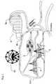
- Fig. 1 is a schematic representation of a first section of an amusement park having a variety of rides in accordance with one embodiment of the present invention.
- the rides include a pirate boat ride 2, a looping boat ride 4, a saucer tea cup ride 5, a roller coaster ride 8 and a Ferris wheel ride.
- a second section of the amusement park is shown having swing ride 12, a water flume ride 15 and an adventure theater 20.
- Each of the rides includes an entrance and an exit and corresponding loading and unloading areas.
- the roller coaster ride 8 includes a loading zone 8a and an unloading zone 8b.
- the swing ride 12 has a loading zone 12a and an unloading zone 12b
- the water flume ride 15 has a loading zone 15a and an unloading zone 15b.
- Each of the above mentioned rides is configured to receive and secure automotive vehicles such as the car V shown in Fig. 5. Each ride is therefore provided with a plurality of car supporting mechanisms 25, such as the car supporting mechanisms 25 shown in Fig. 3 on the saucer tea cup ride 5.
- the saucer tea cup ride 5 includes a large saucer 5a which is connected to a large motor (not shown) such that the large saucer 5a may be rotated about a central axis thereof.
- Within the structure of the large saucer 5a are four intermediate saucers 5b which are each provided with power to rotate about a central axis thereof while the large saucer 5a is rotated.
- each intermediate saucer 5b has four small saucers 5c which rotate about a central axis thereof while the saucers 5a and 5b are rotated.
- Each small saucer 5c includes four car supporting mechanisms 25, which are described in greater detail below.
- an adventure theater 20 is depicted.
- the adventure theater 20 includes a platform supported by a plurality of pressure controlled cylinders such that the platform may be moved in accordance with images projected on a screen.
- the theater 20 includes an on ramp 20a and an off ramp 20b.
- the theater 20 is also provided with a plurality of car supporting mechanisms 25.
- Figs. 5 through 11 depict various types of a car support mechanisms 25 used in the rides in the amusement park.
- Each ride in the amusement park has its own dynamics, each with different requirements for securing cars safely during the ride.
- the car support mechanism includes a platform 30 that includes a support bar 31 which may be made of a strong metal material coated with soft foam material to protect against contact with the car V.
- a swinging rear gate 32 is moveable up and down as indicated by the Arrow A and powered by a pressure cylinder (not shown).
- the sliding bar 35 is secured to the platform 30 but may slide along the pins 36.
- the sliding movement of the bar 35 is limited by the length of an elongated groove 35a. Movement of the bar 35 is controlled by a pressure cylinder 40 that is secured at one end to the platform 30 and secured to the bar 35 at the other end.
- a front gate 42 is pivotally mounted to the bar 35. Movement of the front gate 42 is controlled by a cylinder 43.
- the platform 30 is further provided with a plurality of rollers 45.
- the rollers 45 are all generally parallel within the platform 30 and are freely rotatable.
- a braking mechanism (not shown) is mounted within the platform 30 for selectively restricting the rolling movement of the rollers 45.
- the car supporting mechanism depicted in Figs. 5 and 6 operates as follows.
- the rear gate 32 is lowered and the bar 35 is moved to a forward most position.
- the brake mechanism (not shown) is engaged such that the rollers 45 may not rotate within the platform 30.
- a car V is then driven onto the platform 30 and the rollers 45.
- the rear gate 32 is raised and the front gate 42 is moved toward the front of the car V by positioning the sliding bar 35.
- the front and rear gates 42 and 32 are lined with a soft material such as foam in order to protect the car V from damage in the event of contact therebetween.
- the brake mechanism (not shown) is disengaged such that the rollers 45 may rotate freely within the platform 30.
- the car V is secured within the car support mechanism 25 but may not move due to the front and rear gates 42 and 32.
- the motor of the car V is running and the driver accidently presses on the accelerator, there is no risk of damage to the car V since the rollers 45 may rotate freely. Since the tires of the car V are engaged with the rollers 45, there is no danger of the car V leaving the car supporting mechanism 25 depicted in Figs. 5 and 6.
- the car support mechanism 25 depicted in Figs. 5 and 6 is suitable for most of the rides in the amusement park but is particularly suitable for the boat rides 2 and 4 and for the roller coaster ride 8.
- a car can be driven easily onto the car supporting mechanism 25 and the car supporting mechanism moves in the amusement ride with the passengers of the car V in relative safety.
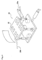
- FIG. 7 and 8 Another car support mechanism is depicted in Figs. 7 and 8.
- a car V is driven onto a platform 60 until the car V is approximately positioned adjacent to openings 60a.
- arms 61 are moved upward on either side of each tire of the car V.
- the arms 61 can be moved toward one another until engaged with the tire.
- the movement of the arms 61 is controlled by the cylinders 62 and 63.
- the arms 61 securely hold the car V in position on the platform 60.
- Such a configuration of the car support mechanism may be used on, for instance, the saucer tea cup ride 5.
- FIG. 9 A further car support mechanism is depicted in Fig. 9 where an arm 65 is extendable upward out of a platform 66.
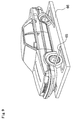
- the car support mechanisms 25 are supported in the rides in various ways. For instance, in both the roller coaster ride 8 and the water flume ride 15, the car support mechanism 25 is supported on rails R by support structures fixed to a lower portion of the car support mechanism 25, where the support structures include a plurality of wheels which engage the rails R. As shown in Fig. 10, the rails may be submerged under water.
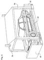
- the car support mechanism 25 depicted in Fig. 11 includes the rollers 45, the front and rear gates 42 and 32 and a support structures 70 and 75 which allow for the car V to be lifted up.
- the cars would be driven onto the platforms of the car support mechanism 25 depicted in Fig. 11, then the central support of the swing ride 12 moves upward, the car support mechanisms are lifted off the ground and swung slowly around.
- the Ferris wheel 10 lifts the car support mechanisms off the ground as the Ferris wheel rotates.
- the car support mechanism includes a platform 130.
- the platform 130 includes upright sides 135 on three sides thereof.
- the sides 135 are formed with a plurality of recesses 136.
- an inflatable bag such as the bags B 1 , B 2 , B 3 , B 4 and B 5 .
- the bags B 1 , B 2 , B 3 , B 4 and B 5 are sealed bags made of a durable air tight material and may include various plies in order to provide an air tight seal.
- the outer ply of the bags B 1 , B 2 , B 3 , B 4 and B 5 is soft so that it is unlikely that the outer surface of the bags B 1 , B 2 , B 3 , B 4 and B 5 can harm painted surfaces, such as the surfaces of a car.
- the bags B 1 , B 2 , B 3 , B 4 and B 5 are connected to an inflation control system 150, as is depicted in Fig. 13.
- the inflation control system 150 includes a controller 155 that is connected to a valve/sensor control 156.
- the valve/sensor control 156 is in turn connected to a compressed air tank 157 that is supplied with compressed air from a compressor 158.
- the valve/sensor control 156 includes a plurality of valves, each valve for selectively supplying compressed air to the bags B 1 , B 2 , B 3 through B N .
- the bag B N is not depicted but is rather a representation of all the inflatable bags that may be included in the present invention.
- Each valve is controlled by the controller 155.
- Each valve includes a sensor (not shown) for sensing the air pressure in each bags B 1 , B 2 , B 3 through B N .
- the car support mechanism depicted in Fig. 12 includes a total of eight (8) inflatable bags, including bags B 1 , B 2 , B 3 and B 5 . Each bag is inflatable to a predetermined pressure for securing a car on the platform 130.
- the platform 130 includes a gate 140 on which the bag B 5 is secured.
- a car may be driven onto the platform 130, as is shown in Fig. 14.
- the gate 140 is raised and an operator may manipulate controls on the controller 155 causing the bags, including bags B 1 , B 2 , B 3 and B 5 to inflate. In an inflated condition, the bags engage the sides, front and rear of the car securely retaining the car on the platform 130.
- the sensors (not shown) associated with the valves in the valve/sensor control 156 may be used to monitor the pressure within the bags B 1 , B 2 , B 3 and B N .
- the pressure within the bags provides an indication of engagement with the car. Therefore, if the bags are inflated to a predetermined air pressure, it can be determined that the car is secured on the platform 130.
- the amusement ride utilizing the platform 130 can safely commence with the car safely in position on the platform 130. After completion of the ride, the operator may manipulate controls (not shown) on the controller 155 to release the pressure from the inflatable bags out an exhaust 159 so that the bags may retract into the recesses 136, the gate 140 may drop down and the car drive out to the next ride.
- the platform 130 may be provided with any of a variety bag configurations. For instance, as is shown in Fig. 15, there may only four (4) bags, bags B 1a , B 2a , B 3a and B 5a on the platform 130. Other combinations of inflatable bags and sizes of inflatable bags are of course possible.
- the platform 130 may be configured in a variety of ways for use on a variety of amusement rides. For instance, as shown in Fig. 16, the platform 130 may be configured for a ride which supports the platform 130 on rails R 1 and R 2 . Or, alternatively, the platform 130 may be supported from above, as depicted in Fig. 17, for use on the swing 12 or the Ferris Wheel 10.
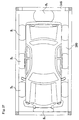
- FIG. 18 Yet another embodiment of the present invention is depicted in Figs. 18 and 19.
- a support mechanism having a platform 230 is formed with a plurality of recesses 235.
- each recess 235 there is disposed an inflatable bag 240.
- the inflatable bags 240 are similar to the bags B 1 , B 2 , B 3 through B N described above.
- a control system such as the control system depicted in Fig. 13 is used to control the inflation condition of the bags 240.
- the bags 240 are inflatable for securing a car V to the platform 230.
- the platform 230 depicted in Figs. 18 and 19 is provided with at least four bags 240, although only three bags 240 are visible.
- One bag 240 is positioned on each side of the platform 230 corresponding to sides of the car V.
- one bag 240 is positioned forward from front wheels of the car V and one bag 240 is positioned rearward from rear wheels of the car V.
- the positioning of the bags 240 on the platform 230 is such that the wheels of the car V are blocked against rotation with the bags 240 in an inflated state. Further, the bags 240 on either side of the car V are positioned to engage doors of the car V thus preventing the doors from opening with the bags 240 in an inflated state, as shown in Fig. 19.
- the support mechanism depicted in Figs. 18 and 19 provides a reliable and safe way to restrain a vehicle on the platform 230 in a simple manner.
- the bags 240 are may be made of any of a variety of materials making in possible for the car to roll over the bags 240 when entering the platform 230 and leaving the platform 230.
- the bags 240 may be elastic or may have an elastic element or elements formed on an outside surface or within the bags 240.
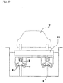
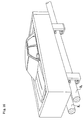
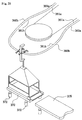
- a means for holding the vehicle against the surface of the platform of the support mechanism is included in the support mechanism depicted in Fig. 20.
- the support mechanism depicted in Fig. 20 is generally the same as the support mechanism depicted in Figs. 18 and 19, except that the upper support mechanism 260 is fixed to the platform 230.
- the upper support mechanism 260 includes an upright support 261 fixed to the platform 230, a telescoping member 262 that extends upward from the upright support 261 and a support structure 263 which is fixed to the telescoping member 262. on a lower surface of the support structure 263 is a cushion 265.
- the cushion 265 could alternatively be an inflatable bag.
- the telescoping member 262 may be moved up and down by control means (not shown) such as a crank lever, a hydraulic or pneumatic cylinder or other such device. By moving the telescoping member 262, the cushion 265 may be brought into engagement with the roof of the car V, thus securing the car V against movement up and down relative to the platform 230.
- the upper support mechanism 260 is not limited to the structure as shown.
- the upper support mechanism 260 could be used with any of the embodiments of the present invention.
- the upper support mechanism 260 is not limited to a single upright support member. In some applications it may be desirable to utilize several support members in the upper support mechanism 260.
- the telescoping member 262 need not be used. Rather the support structure 263 may be directly fixed to the upright support 261 and an inflatable bag may be used instead of a cushion.
- a sensor may be employed with a control system for automatically sensing the height of the car V and positioning the cushion 265 against the roof of the car V.
- a cable driven amusement ride is configured to support and move a plurality of carriages, each carriage able to support a car.
- the cable driven amusement ride may be used in, for instance, environmentally sensitive areas where the building of roads would intrude upon the local environment. Since people love to view nature from the comfort of their own car, the cable driven ride in accordance with the present invention provides a means for people to enjoy a ride through a valley or about a mountain side compassion without a road intruding upon the natural beauty of the scene.
- the cable driven amusement ride includes two terminals T and at least one tower 301, although a plurality of towers 301 may be utilized.
- Each tower includes rollers that may be protected by a cover 302, as shown in Fig. 21B, the rollers supporting a cable C and allowing the cable C to move with respect to the tower 301 as the cable is pulled between the terminals T.
- the cable C extends between a plurality of the towers 301 over natural terrain.
- the towers 301 may be spaced apart by a distance of hundreds of meters with the cable extending therebetween.
- the cable is moved between adjacent towers 301 such that the passenger vehicle moves above a scenic view.
- the cable C supports a plurality of carriages 325, each carriage 325 able to support a car in much the same way as the support mechanisms discussed above with respect to Figs. 1-20.
- Each carriage 325 as shown in Figs. 21B, 22 and 23, includes at least one cable hook 330 that engages the cable C, thereby causing the carriages 325 to move along with the cable C.
- the cable hook 330 is part of a support assembly that also includes rollers 332. In the embodiment depicted in Figs. 21B and 22, the support assembly includes four rollers 332 and two cable hooks 330.
- Each of the carriages 325 includes a frame structure that includes upright support beams 340, angled support beams 341 and a support plate 342, all rigidly fixed to one another.
- the lower portion of the frame structure includes three side panels 343 and one gate 345, described further below.
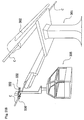
- the cable driven amusement ride includes at least one terminal T, depicted in Figs. 23, 24 and 25.
- Each of the two terminals T supports the cable as is rotates in an endless belt manner between the two terminals T.
- each of the terminals includes a motor 350 and a pulley 351 that engages the cable C. As the motor 350 rotates, the cable C is moved along the rollers of the towers 301 thereby moving the carriages 325.
- the terminal is also provided with a pair of tracks 360 and 361 that have a U-shape, as shown in a top view in Fig. 24.
- the tracks 360 and 361 are supported from above by supports 368.
- Portions 360a and 361a of the tracks 360 and 361 are positioned adjacent to the cable C at points along the cable C just before the cable C engages the pulley 351 and just after the cable C leaves the pulley 351.
- the portions 360a (and 361a) are bent such that they are slightly higher than the cable C.
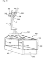
- the cable hooks 330 engaged with cable C. Movement of the cable C causes the rollers 332 to eventually contact the tracks 360 and 361. As the carriage 325 continues to move toward the pulley 351 with the cable C, the rollers 330 begin to roll over the portions 360a and 361a of the tracks 360 and 361. Therefore, the carriage is lifted up such that the cable hooks 330 are lifted away from contact with the cable C. Momentum keeps the carriages 325 rolling on the tracks 360 and 361 until the tracks engage the portions 360b and 361b, which are bent away from the pulley, thereby causing the cable hooks 330 to be moved away from the cable C. The carriage 325 is then able to roll to the arcuate portion of the tracks 360 and 361 above a platform 370.
- the platform 370 is supported by a plurality of cylinders 372 that allow upward and downward movement of the platform 370.
- the cylinders 372 may be either hydraulic, pneumatic or electric devices which provide controllable movement of the platform 370.
- the platform is raised to support the carriage 325 to prevent it from moving as a car is moved in and out of the carriage 325.
- the gate 345 may then be lowered and a ramp 375 shown in Fig. 25 may be moved to a position adjacent to the platform 370 and gate 345 to allow a car to move in or out of the carriage 325.
- the gate 345 may be closed, the ramp 375 moved out of the way, and the platform 370 lowered out of the way.
- the carriage 325 Due to the presence of the rollers 332 being engaged with the tracks 360 and 361, the carriage 325 is easily pushed either by manual operators along the tracks 360 and 361 to the portions 360b and 361b of the tracks, and subsequently to the portions 360a and 360b. Once the cable hooks 330 contact the cable C, the carriage 325 then moves with the cable C and the roller 332 become dis-engaged from the tracks 360 and 361.
- Fig. 25 does not show the motor 350 or the supports 368 in order to provide greater clarity of the various features of the present invention.
- the carriage 325 described above is basically a cage which supports a car in the cable driven ride. There are many different sizes, shapes and configurations of car and therefore, ideally, the carriages 325 should be able to accommodate as many different types of cars as possible. For that reason, several embodiments of the carriages 325 are contemplated.
- the carriage 380 includes an open structure similar to the carriage 325.
- the carriage 380 includes the supports beams 340 and 341, as well as the gate 345 and side panels 343.
- the carriage 380 also includes a plurality of inflatable bags B 1 , B 2 , B 3 through B N , similar to the bags described above with respect to Figs. 12, 13 and 14.
- the bags B 1 , B 2 , B 3 through B N surround a car as shown in Fig. 27, thereby securing the car within the carriage 380.
- the bags B 1 , B 2 , B 3 through B N may be inflated by any of a variety of means.
- a single air inlet/outlet I/O may be provided on the carriage 380 and connected to each of the bags B 1 , B 2 , B 3 and B N via pressure tubes (not shown).
- An operator may inflate the bags using pressurized air before launching the carriage 380 on the cable C via the tracks 360 and 361.
- An air compressor (not shown) and air supply hose (not shown) are provided in the terminal adjacent to the platform 370 for inflating the bags B 1 , B 2 , B 3 through B N .
- the bags B 1 , B 2 , B 3 through B N are deflated by releasing the air pressure via the inlet/outlet I/O.
- the platform 380 may be provided with fewer bags, each bag being larger than the bags shown in Fig. 27.
- bags B 1a , B 2a , B 3a and B 4a may be provided on the side panels of the platform 380 as shown in Figs. 28.
- the bags B 1a , B 2a , B 3a and B 5a may be inflated and deflated via an inlet/outlet I/O that is connected via pressure tubes (not shown) to each of the bags B 1a , B 2a , B 3a and B 5a ⁇
- a carriage 400 is also contemplated.
- the carriage 400 is depicted in Figs. 29 and 20 and includes a gate 42
- the car support mechanism includes a platform and support structure that includes a support bar 31 which may be made of a strong metal material coated with soft foam material to protect against contact with the car.
- a swinging rear gate 32 is moveable up and down.
- the sliding bar 35 is secured to the platform but may slide along the pins 36.
- the sliding movement of the bar 35 is limited by the length of an elongated groove 35a. Movement of the bar 35 is controlled by a pressure cylinder 40 that is secured at one end to the platform and secured to the bar 35 at the other end.
- a front gate 42 is pivotally mounted to the bar 35. Movement of the front gate 42 is controlled by a cylinder 43.
- the cylinders 40 and 43 include a locking mechanism (not shown) such that after being put into position, if air pressure is reduced, the cylinders 40 and 43 are locked into position until air pressure within the cylinders is restored. In this manner, the cylinders 40 and 43 may only be moved when air pressure is supplied by an operator in the terminal. Therefore, while moving with the cable in the cable driven ride, the carriage 400 safely retains the car.
- the platform 30 is further provided with a plurality of rollers 45.
- the rollers 45 are all generally parallel within the platform 30 and are freely rotatable.
- a braking mechanism (not shown) is mounted within the platform 30 for selectively restricting the rolling movement of the rollers 45. Specifically, the rollers 45 may only be locked and unlocked by an operator at the terminal to allow the car to enter and leave the carriage 400.
- the carriage depicted in Figs. 29 and 30 operates as follows.
- the rear gate 32 is lowered and the bar 35 is moved to a forward most position by an operator at the terminal.
- the brake mechanism (not shown) is engaged such that the rollers 45 may not rotate within the platform 30.
- a car is then driven onto the carriage 400 and the rollers 45.
- the rear gate 32 is raised and the front gate 42 is moved toward the front of the car by an operator who uses air pressure from an air hose (not shown) to position the sliding bar 35 and front gate 42.
- the front and rear gates 42 and 32 are lined with a soft material such as foam in order to protect the car from damage in the event of contact therebetween.
- the brake mechanism (not shown) is disengaged such that the rollers 45 may rotate freely within the platform 30.
- the car is secured within the car support mechanism 25 but may not move due to the front and rear gates 42 and 32.
- the motor of the car is running and the driver accidently presses on the accelerator, there is no risk of damage to the car since the rollers 45 may rotate freely. Since the tires of the car are engaged with the rollers 45, there is no danger of the car leaving the platform 400.
- the cable driven amusement ride described above is ideal for areas that have difficult terrain to drive over or that are protected against development.
- the cable driven amusement ride may be used in mountainous areas or wilderness areas where roads are either intrusive or difficult and costly to build. Since the cable driven ride may pass above such areas, there is little if any intrusion by the car on the environment because the car do not need a road and do not necessarily have their motors running while on the cable driven amusement ride.
- the cable driven amusement ride may alternatively be what is often referred to as a cable car amusement ride where there are only two carriages employed.
- the carriages are fixed to the cable such that when the first carriage is in a first terminal, the second carriage is located in the second terminal.
- the two carriages move toward one another as the cable rotates between the terminals.
- the two carriages pass one another and continue moving toward the opposite terminal.
- the ramp 375 and tracks 360 and 361 would not be necessary since the cable must stop moving as the cars approach the terminals.
- the carriages are unloaded simultaneously. In other words, when the first carriage moves toward the second carriage, the second carriage moves in the opposite direction towards the first carriage.
- the two carriages trade places going back and forth between the two terminal.
- the present invention is intended to apply to such a cable car amusement ride.
Abstract
Description
Claims (22)
- An amusement park comprising:at least one amusement ride, characterised in that said amusement ride includes a plurality of a car support mechanisms, wherein each of said car support mechanisms is configured to receive and support a car (V) with passengers inside and said amusement ride is configured to move said plurality of car support mechanisms in accordance with the thrills of said amusement ride.
- The amusement park as set forth in claim 1, wherein said amusement ride is a roller coaster.
- The amusement park as set forth in claim 2 wherein said car support mechanism includes a front and a rear gate which secure the car thus preventing movement of the car with respect to the car supporting mechanism.
- The amusement park as set forth in claim 1, wherein said amusement ride is an adventure theater.
- The amusement park as set forth in claim 4 wherein said car support mechanism includes a mechanism for restraining movement of the tires of the car.
- The amusement park as set forth in claim 1, wherein said amusement ride is a saucer tea cup ride.
- The amusement park as set forth in claim 1, wherein said amusement ride is a swing ride.
- The amusement park as set forth in claim 1, wherein said amusement ride is a Ferris wheel.
- The amusement park as set forth in claim 1, wherein each of said car support mechanisms includes a platform and front and rear gates supported on said platform, said front and rear gates being configured to secure the car to said platform thus preventing movement of the car with respect to the car supporting mechanism, and said platform being further provided with a plurality of rollers which may be selectively braked against rolling movement.
- The amusement park as set forth in claim 1 wherein said car support mechanism comprises:a generally flat platform upon which a car is positionable;at least two generally upright sides extending from said platform; andat least one inflatable bag being fixed to at least one of said upright sides, upon inflation, said inflatable bag being configured to engage and secure the car on said platform.
- The amusement park as set forth in claim 10, said car supporting mechanism further comprising a gate mounted to said platform, said gate including a second inflatable bag.
- The amusement park as set forth in claim 11, wherein said car support mechanism includes means for supporting said platform on an underside thereof for use on said amusement ride, said amusement ride being configured with tracks for receiving said support means.
- The amusement park as set forth in claim 11, wherein said car support mechanism includes means for supporting said platform on an upperside thereof for use on said amusement ride, said amusement ride including means for lifting said platform from an upper side thereof.
- The amusement park as set forth in claim 1 wherein said car support mechanism comprises:a generally flat platform upon which a car is positionable;at least one first inflatable bag being fixed to said platform, said first inflatable bag being configured to engage and secure the car on said platform by preventing wheels of the car from rotating.
- The amusement park as set forth in claim 14 wherein said car support mechanism further comprises:a second inflatable bag fixed to said platform proximate a rearward side of the car and said first inflatable bag being positioned proximate a forward side of the car.
- The amusement park as set forth in claim 15 wherein said car support mechanism further comprises a means for contacting an upper surface of the car for restraining upward movement of the car.
- The amusement park as set forth in claim 1 wherein each of said car support mechanisms further comprises a means for contacting an upper surface of the car for restraining upward movement of the car with respect to the car support mechanism.
- A cable driven amusement ride comprising:at least one supporting tower (301);at least one terminal (T) spaced apart from said supporting tower;a cable (C) extending between said tower and said terminal, characterised in that, said cable is supported by said tower such that said cable is continuously moveable between said tower and said terminal;and in that the cable driven amusement ride further comprises means (350) for moving said cable between said tower and said terminal;at least one carriage (325) engagable with said cable such that said carriage is moveable with said cable between said tower and said terminal; andsaid carriage is configured to support and carry a car (V).
- The cable driven amusement ride as set forth in claim 18 wherein said carriage includes a front gate which secures the car thus preventing movement of the car with respect to the carriage.
- The cable driven amusement ride as set forth in claim 18 wherein said carriage includes a platform and front and rear gates supported on said platform, said front and rear gates being configured to secure the car to said platform thus preventing movement of the car with respect to the carriage, and said platform being further provided with a plurality of rollers which may be selectively braked against rolling movement.
- The cable driven amusement ride as set forth in claim 18 wherein said carriage comprises:a generally flat platform upon which car is positionable;at least two generally upright sides extending from said platform; andat least one inflatable bag being fixed to at least one of said upright sides, upon inflation, said inflatable bag being configured to engage and secure the car on said platform.
- The cable driven amusement ride as set forth in claim 21, said carriage further comprising a gate mounted to said platform, said gate including a second inflatable bag.
Applications Claiming Priority (5)
| Application Number | Priority Date | Filing Date | Title |
|---|---|---|---|
| US09/149,030 US6162127A (en) | 1998-09-08 | 1998-09-08 | Amusement park with rides conveying park-goers in their own motor vehicles |
| US149030 | 1998-09-08 | ||
| US09/385,852 US6210284B1 (en) | 1998-09-08 | 1999-08-30 | Rides conveying park-goers in their own motor vehicles |
| US385852 | 1999-08-30 | ||
| PCT/JP1999/004777 WO2000013759A1 (en) | 1998-09-08 | 1999-09-02 | Amusement park with passenger vehicle carrying rides |
Publications (2)
| Publication Number | Publication Date |
|---|---|
| EP1112112A1 EP1112112A1 (en) | 2001-07-04 |
| EP1112112B1 true EP1112112B1 (en) | 2004-11-03 |
Family
ID=26846410
Family Applications (1)
| Application Number | Title | Priority Date | Filing Date |
|---|---|---|---|
| EP99940639A Expired - Lifetime EP1112112B1 (en) | 1998-09-08 | 1999-09-02 | Amusement park with passenger vehicle carrying rides |
Country Status (10)
| Country | Link |
|---|---|
| US (1) | US6210284B1 (en) |
| EP (1) | EP1112112B1 (en) |
| JP (1) | JP3490063B2 (en) |
| KR (1) | KR100563105B1 (en) |
| CN (1) | CN1315880A (en) |
| AT (1) | ATE281220T1 (en) |
| AU (1) | AU756698B2 (en) |
| CA (1) | CA2340009C (en) |
| DE (1) | DE69921669T2 (en) |
| WO (1) | WO2000013759A1 (en) |
Families Citing this family (4)
| Publication number | Priority date | Publication date | Assignee | Title |
|---|---|---|---|---|
| US9526997B2 (en) * | 2014-07-22 | 2016-12-27 | Universal City Studios Llc | Vehicle transportation room system and method |
| DE102017007330A1 (en) * | 2017-08-17 | 2019-02-21 | ROLLERCOASTERRESTAURANT Entertainment GmbH | Pickup, transport, and / or movement system for vehicles |
| US11287815B2 (en) * | 2018-10-05 | 2022-03-29 | Universal City Studios Llc | Autonomous vehicle transporation systems and methods |
| US10814236B1 (en) * | 2019-04-29 | 2020-10-27 | Universal City Studios Llc | Coaster transportation system |
Citations (1)
| Publication number | Priority date | Publication date | Assignee | Title |
|---|---|---|---|---|
| US535938A (en) * | 1895-03-19 | Coaster |
Family Cites Families (13)
| Publication number | Priority date | Publication date | Assignee | Title |
|---|---|---|---|---|
| US3247539A (en) * | 1962-08-22 | 1966-04-26 | William W Pleasants | Suspended overpass |
| US3355580A (en) * | 1965-10-13 | 1967-11-28 | Coney Island Inc | Sky ride |
| FR2505198A1 (en) * | 1981-05-05 | 1982-11-12 | Loisel Paul | ATTRACTION FORAINE MANEGE-TRAIN |
| JPH0684205B2 (en) * | 1987-11-20 | 1994-10-26 | 株式会社椿本チエイン | Suspended transport device with L-shaped hanger |
| US4909155A (en) * | 1988-08-31 | 1990-03-20 | Mazda Motor Manufacturing (U.S.A.) Corporation | Auto body holding means for auto body conveyor apparatus with side sill holding means that accepts different sized side sills |
| FR2649386B1 (en) * | 1989-07-10 | 1996-02-02 | Webb Int Co Jervis B | CONVEYOR SYSTEM WITH CONSOLE TRAYS |
| US5192247A (en) * | 1991-03-27 | 1993-03-09 | Universal City Studios, Inc. | Ride attraction |
| JPH0717394A (en) | 1992-03-19 | 1995-01-20 | Anzen Sakudo Kk | Landing system for ropeway |
| DE4227609C2 (en) * | 1992-08-20 | 1995-12-21 | Siemens Ag | Device for space-saving parking of motor vehicles |
| JPH08239033A (en) | 1995-03-04 | 1996-09-17 | Anzen Sakudo Kk | Rope gripping machine in rope way |
| JPH08282476A (en) | 1995-04-17 | 1996-10-29 | Anzen Sakudo Kk | Cable gripping machine of cableway |
| US5935011A (en) * | 1998-04-30 | 1999-08-10 | Universal City Studios, Inc. | Wheelchair accessible carousel vehicle |
| US5853331A (en) * | 1998-05-06 | 1998-12-29 | Bungee Japan, Inc. | Amusement ride |
-
1999
- 1999-08-30 US US09/385,852 patent/US6210284B1/en not_active Expired - Fee Related
- 1999-09-02 AU AU54485/99A patent/AU756698B2/en not_active Ceased
- 1999-09-02 DE DE69921669T patent/DE69921669T2/en not_active Expired - Lifetime
- 1999-09-02 EP EP99940639A patent/EP1112112B1/en not_active Expired - Lifetime
- 1999-09-02 CN CN99810300A patent/CN1315880A/en active Pending
- 1999-09-02 AT AT99940639T patent/ATE281220T1/en not_active IP Right Cessation
- 1999-09-02 JP JP2000568562A patent/JP3490063B2/en not_active Expired - Fee Related
- 1999-09-02 WO PCT/JP1999/004777 patent/WO2000013759A1/en active IP Right Grant
- 1999-09-02 CA CA002340009A patent/CA2340009C/en not_active Expired - Fee Related
- 1999-09-02 KR KR1020017002896A patent/KR100563105B1/en not_active IP Right Cessation
Patent Citations (1)
| Publication number | Priority date | Publication date | Assignee | Title |
|---|---|---|---|---|
| US535938A (en) * | 1895-03-19 | Coaster |
Also Published As
| Publication number | Publication date |
|---|---|
| ATE281220T1 (en) | 2004-11-15 |
| DE69921669T2 (en) | 2005-10-20 |
| WO2000013759A1 (en) | 2000-03-16 |
| JP3490063B2 (en) | 2004-01-26 |
| JP2002524164A (en) | 2002-08-06 |
| KR20010079750A (en) | 2001-08-22 |
| CA2340009C (en) | 2008-01-29 |
| KR100563105B1 (en) | 2006-03-27 |
| DE69921669D1 (en) | 2004-12-09 |
| AU756698B2 (en) | 2003-01-23 |
| CN1315880A (en) | 2001-10-03 |
| CA2340009A1 (en) | 2000-03-16 |
| EP1112112A1 (en) | 2001-07-04 |
| US6210284B1 (en) | 2001-04-03 |
| AU5448599A (en) | 2000-03-27 |
Similar Documents
| Publication | Publication Date | Title |
|---|---|---|
| US6162127A (en) | Amusement park with rides conveying park-goers in their own motor vehicles | |
| US4543886A (en) | Amusement ride including a rotating loading terminal | |
| US5564984A (en) | Double hull amusement ride vehicle | |
| JP2008540054A (en) | Wheel hub vehicle carrier | |
| US20050288114A1 (en) | System and apparatus for propelling and carrying a user within a confined interior | |
| US5884563A (en) | Ride attraction system for the physically disabled | |
| US7666103B2 (en) | Amusement ride | |
| US8096890B2 (en) | Amusement ride assembly and method | |
| EP1112112B1 (en) | Amusement park with passenger vehicle carrying rides | |
| CA2601280C (en) | Amusement park with passenger vehicle carrying rides | |
| US5586503A (en) | Passenger restraint system | |
| JP2002524164A5 (en) | ||
| JPH09505230A (en) | Swing-type entertainment vehicle device with pendulum damping means | |
| EP0137780B1 (en) | Amusement ride loading terminal | |
| CA3151785C (en) | Rail vehicle with human and/or electric power | |
| WO2010053384A1 (en) | Rotating barrel ride | |
| KR20240039671A (en) | Nonstop Boarding Available Leg Folding Wheel Chair | |
| JP2000176178A (en) | Amusement equipment | |
| TH59129B (en) | Set of seat belts for wheelchairs |
Legal Events
| Date | Code | Title | Description |
|---|---|---|---|
| PUAI | Public reference made under article 153(3) epc to a published international application that has entered the european phase |
Free format text: ORIGINAL CODE: 0009012 |
|
| 17P | Request for examination filed |
Effective date: 20010216 |
|
| AK | Designated contracting states |
Kind code of ref document: A1 Designated state(s): AT BE CH CY DE DK ES FI FR GB GR IE IT LI LU MC NL PT SE |
|
| GRAP | Despatch of communication of intention to grant a patent |
Free format text: ORIGINAL CODE: EPIDOSNIGR1 |
|
| GRAS | Grant fee paid |
Free format text: ORIGINAL CODE: EPIDOSNIGR3 |
|
| GRAA | (expected) grant |
Free format text: ORIGINAL CODE: 0009210 |
|
| AK | Designated contracting states |
Kind code of ref document: B1 Designated state(s): AT BE CH CY DE DK ES FI FR GB GR IE IT LI LU MC NL PT SE |
|
| PG25 | Lapsed in a contracting state [announced via postgrant information from national office to epo] |
Ref country code: NL Free format text: LAPSE BECAUSE OF FAILURE TO SUBMIT A TRANSLATION OF THE DESCRIPTION OR TO PAY THE FEE WITHIN THE PRESCRIBED TIME-LIMIT Effective date: 20041103 Ref country code: LI Free format text: LAPSE BECAUSE OF FAILURE TO SUBMIT A TRANSLATION OF THE DESCRIPTION OR TO PAY THE FEE WITHIN THE PRESCRIBED TIME-LIMIT Effective date: 20041103 Ref country code: FI Free format text: LAPSE BECAUSE OF FAILURE TO SUBMIT A TRANSLATION OF THE DESCRIPTION OR TO PAY THE FEE WITHIN THE PRESCRIBED TIME-LIMIT Effective date: 20041103 Ref country code: CH Free format text: LAPSE BECAUSE OF FAILURE TO SUBMIT A TRANSLATION OF THE DESCRIPTION OR TO PAY THE FEE WITHIN THE PRESCRIBED TIME-LIMIT Effective date: 20041103 Ref country code: BE Free format text: LAPSE BECAUSE OF FAILURE TO SUBMIT A TRANSLATION OF THE DESCRIPTION OR TO PAY THE FEE WITHIN THE PRESCRIBED TIME-LIMIT Effective date: 20041103 Ref country code: AT Free format text: LAPSE BECAUSE OF FAILURE TO SUBMIT A TRANSLATION OF THE DESCRIPTION OR TO PAY THE FEE WITHIN THE PRESCRIBED TIME-LIMIT Effective date: 20041103 |
|
| REG | Reference to a national code |
Ref country code: GB Ref legal event code: FG4D |
|
| REG | Reference to a national code |
Ref country code: CH Ref legal event code: EP |
|
| REF | Corresponds to: |
Ref document number: 69921669 Country of ref document: DE Date of ref document: 20041209 Kind code of ref document: P |
|
| REG | Reference to a national code |
Ref country code: IE Ref legal event code: FG4D |
|
| PG25 | Lapsed in a contracting state [announced via postgrant information from national office to epo] |
Ref country code: SE Free format text: LAPSE BECAUSE OF FAILURE TO SUBMIT A TRANSLATION OF THE DESCRIPTION OR TO PAY THE FEE WITHIN THE PRESCRIBED TIME-LIMIT Effective date: 20050203 Ref country code: GR Free format text: LAPSE BECAUSE OF FAILURE TO SUBMIT A TRANSLATION OF THE DESCRIPTION OR TO PAY THE FEE WITHIN THE PRESCRIBED TIME-LIMIT Effective date: 20050203 Ref country code: DK Free format text: LAPSE BECAUSE OF FAILURE TO SUBMIT A TRANSLATION OF THE DESCRIPTION OR TO PAY THE FEE WITHIN THE PRESCRIBED TIME-LIMIT Effective date: 20050203 |
|
| PG25 | Lapsed in a contracting state [announced via postgrant information from national office to epo] |
Ref country code: ES Free format text: LAPSE BECAUSE OF FAILURE TO SUBMIT A TRANSLATION OF THE DESCRIPTION OR TO PAY THE FEE WITHIN THE PRESCRIBED TIME-LIMIT Effective date: 20050214 |
|
| NLV1 | Nl: lapsed or annulled due to failure to fulfill the requirements of art. 29p and 29m of the patents act | ||
| REG | Reference to a national code |
Ref country code: CH Ref legal event code: PL |
|
| PG25 | Lapsed in a contracting state [announced via postgrant information from national office to epo] |
Ref country code: IE Free format text: LAPSE BECAUSE OF NON-PAYMENT OF DUE FEES Effective date: 20050902 Ref country code: CY Free format text: LAPSE BECAUSE OF FAILURE TO SUBMIT A TRANSLATION OF THE DESCRIPTION OR TO PAY THE FEE WITHIN THE PRESCRIBED TIME-LIMIT Effective date: 20050902 |
|
| PLBE | No opposition filed within time limit |
Free format text: ORIGINAL CODE: 0009261 |
|
| STAA | Information on the status of an ep patent application or granted ep patent |
Free format text: STATUS: NO OPPOSITION FILED WITHIN TIME LIMIT |
|
| PG25 | Lapsed in a contracting state [announced via postgrant information from national office to epo] |
Ref country code: MC Free format text: LAPSE BECAUSE OF NON-PAYMENT OF DUE FEES Effective date: 20050930 Ref country code: LU Free format text: LAPSE BECAUSE OF NON-PAYMENT OF DUE FEES Effective date: 20050930 |
|
| 26N | No opposition filed |
Effective date: 20050804 |
|
| ET | Fr: translation filed | ||
| REG | Reference to a national code |
Ref country code: IE Ref legal event code: MM4A |
|
| PG25 | Lapsed in a contracting state [announced via postgrant information from national office to epo] |
Ref country code: PT Free format text: LAPSE BECAUSE OF NON-PAYMENT OF DUE FEES Effective date: 20050403 |
|
| PGFP | Annual fee paid to national office [announced via postgrant information from national office to epo] |
Ref country code: IT Payment date: 20100924 Year of fee payment: 12 Ref country code: FR Payment date: 20100930 Year of fee payment: 12 |
|
| PGFP | Annual fee paid to national office [announced via postgrant information from national office to epo] |
Ref country code: GB Payment date: 20100924 Year of fee payment: 12 |
|
| PGFP | Annual fee paid to national office [announced via postgrant information from national office to epo] |
Ref country code: DE Payment date: 20100930 Year of fee payment: 12 |
|
| GBPC | Gb: european patent ceased through non-payment of renewal fee |
Effective date: 20110902 |
|
| PG25 | Lapsed in a contracting state [announced via postgrant information from national office to epo] |
Ref country code: IT Free format text: LAPSE BECAUSE OF NON-PAYMENT OF DUE FEES Effective date: 20110902 |
|
| REG | Reference to a national code |
Ref country code: FR Ref legal event code: ST Effective date: 20120531 |
|
| REG | Reference to a national code |
Ref country code: DE Ref legal event code: R119 Ref document number: 69921669 Country of ref document: DE Effective date: 20120403 |
|
| PG25 | Lapsed in a contracting state [announced via postgrant information from national office to epo] |
Ref country code: DE Free format text: LAPSE BECAUSE OF NON-PAYMENT OF DUE FEES Effective date: 20120403 |
|
| PG25 | Lapsed in a contracting state [announced via postgrant information from national office to epo] |
Ref country code: GB Free format text: LAPSE BECAUSE OF NON-PAYMENT OF DUE FEES Effective date: 20110902 Ref country code: FR Free format text: LAPSE BECAUSE OF NON-PAYMENT OF DUE FEES Effective date: 20110930 |