EP1111954A2 - Distributed optical switching device - Google Patents
Distributed optical switching device Download PDFInfo
- Publication number
- EP1111954A2 EP1111954A2 EP00310721A EP00310721A EP1111954A2 EP 1111954 A2 EP1111954 A2 EP 1111954A2 EP 00310721 A EP00310721 A EP 00310721A EP 00310721 A EP00310721 A EP 00310721A EP 1111954 A2 EP1111954 A2 EP 1111954A2
- Authority
- EP
- European Patent Office
- Prior art keywords
- switch
- output
- input
- segment
- optical
- Prior art date
- Legal status (The legal status is an assumption and is not a legal conclusion. Google has not performed a legal analysis and makes no representation as to the accuracy of the status listed.)
- Granted
Links
Images




Classifications
-
- H—ELECTRICITY
- H04—ELECTRIC COMMUNICATION TECHNIQUE
- H04Q—SELECTING
- H04Q11/00—Selecting arrangements for multiplex systems
- H04Q11/0001—Selecting arrangements for multiplex systems using optical switching
- H04Q11/0062—Network aspects
-
- H—ELECTRICITY
- H04—ELECTRIC COMMUNICATION TECHNIQUE
- H04Q—SELECTING
- H04Q11/00—Selecting arrangements for multiplex systems
- H04Q11/0001—Selecting arrangements for multiplex systems using optical switching
- H04Q11/0005—Switch and router aspects
-
- H—ELECTRICITY
- H04—ELECTRIC COMMUNICATION TECHNIQUE
- H04J—MULTIPLEX COMMUNICATION
- H04J14/00—Optical multiplex systems
- H04J14/02—Wavelength-division multiplex systems
- H04J14/0287—Protection in WDM systems
- H04J14/0293—Optical channel protection
- H04J14/0294—Dedicated protection at the optical channel (1+1)
-
- H—ELECTRICITY
- H04—ELECTRIC COMMUNICATION TECHNIQUE
- H04J—MULTIPLEX COMMUNICATION
- H04J14/00—Optical multiplex systems
- H04J14/02—Wavelength-division multiplex systems
- H04J14/0287—Protection in WDM systems
- H04J14/0293—Optical channel protection
- H04J14/0295—Shared protection at the optical channel (1:1, n:m)
-
- H—ELECTRICITY
- H04—ELECTRIC COMMUNICATION TECHNIQUE
- H04Q—SELECTING
- H04Q11/00—Selecting arrangements for multiplex systems
- H04Q11/0001—Selecting arrangements for multiplex systems using optical switching
- H04Q11/0005—Switch and router aspects
- H04Q2011/0037—Operation
- H04Q2011/0043—Fault tolerance
-
- H—ELECTRICITY
- H04—ELECTRIC COMMUNICATION TECHNIQUE
- H04Q—SELECTING
- H04Q11/00—Selecting arrangements for multiplex systems
- H04Q11/0001—Selecting arrangements for multiplex systems using optical switching
- H04Q11/0062—Network aspects
- H04Q2011/0079—Operation or maintenance aspects
- H04Q2011/0081—Fault tolerance; Redundancy; Recovery; Reconfigurability
Definitions
- the present invention relates to an optical switch, and in particular to a distributed optical switch.
- OSPR optical dedicated protection and optical shared protection rings
- Optical transmission systems are often constructed with a fault recovery mechanism so that if there is a complete loss of transmission capability due to component and/or transmission line failure, the traffic can be reallocated to other physically diverse routes.
- Pending US application no. 09/349,349 (incorporated herein by reference) describes such an OSPR system.
- Switches are commonly incorporated in OSPR's at network nodes.
- a 2x2 switch may be utilised to connect between working and protect transmitters/receivers and working and protect transmission lines.
- the OSPR is designed with a fault recovery mechanism, performance of the node will be seriously affected if a switch fails, or has to be removed for maintenance or in order to be replaced. In such an instance, switch failure maintenance can interrupt both working and protection traffic.
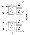
- Figure 1 shows a working (2) and protect (4) transmission line connected to respective working and protect receivers (6,8) via a 2x2 switch (10).
- the working and protect transmission lines (2',4') may be connected to the working and protect transmitters (6',8') via a 2x2 switch (10').
- a bi-directional 2x2 switch and a combination transmitter/receiver can be used before the outgoing and incoming paths are routed to transmitter and receiver respectively. This allows these two switches to be combined into one (not shown).
- a 2x2 switch allows independent connection of working and protection optical channels (or transmission lines) to working or protection receiver or transmitter as appropriate. This functionality is required in both 1+1 (in which the same data is simultaneously transmitted along both the working and protection lines, providing redundancy in the event of either of the lines failing) and 1:1 protection switching (in which high priority data is typically transmitted along the working line, low priority data along the protect line; in the event of the working line failing, the high priority data is routed along the protect line).
- FIG. 2 shows how such bi-directional 2x2 switches may be incorporated into an OSPR module 20, which includes an optical cross connect (oxc) 22.
- the OXC contains optical switches to route traffic off and on the shared protection as described in US application no. 09/349,349.
- An OSPR will be comprised of a number of such modules or nodes.
- optical switch can be used. Many systems, not limited to telecommunications may utilise such optical switching arrangements.
- the failure of a switch, or a part of the switch, inevitably affects connectivity between the inputs and outputs, as does removal of the switch for repair or maintenance.
- the present invention aims to address some of the problems of the prior art.
- the present invention provides an optical switching segment comprising at least one input, at least one output, at least one connector arranged to be connectable to a further segment so as to provide at least one of a further input and a further output, and a switch arranged to selectively connect between two of said input, said output and said connector.
- an optical switching segment comprising at least one input, at least one output, at least one connector arranged to be connectable to a further segment so as to provide at least one of a further input and a further output, and a switch arranged to selectively connect between two of said input, said output and said connector.
- said connector provides a further input and said switch is arranged to selectively connect said output to one of said input or said connector.
- said connector provides a further output and said switch is arranged to selectively connect said input to one of said output and said connector.
- the present invention provides an optical switch comprising at least two segments, each segment having a respective input and a respective output, arranged such that in use if a first segment is removed, a second segment can operate as a pass-through device.
- the present invention provides an optical switch distributed over at least two cards, the first card having a first input and a first output, and the second card having at least one of a second input and a second output, the switch further comprising a switching means arranged to selectively form a connection between two of said first input, said first output, and said second input and output, arranged such that said second card may be removed from communication with said first card whilst the switch is in use, said first card then being arranged to connect said first input to said first output.
- said cards are removably attached.
- detachment of the cards may require destruction or damage to one or more of any components that connect the cards, e.g. the cutting of an optical fibre connection.
- connecting means between the cards comprises at least one of a freespace optical beam path and a waveguide.
- said switching means comprises a selection from the group of polymer waveguides, mach-zehnders and MEMS (micro-electro mechanical systems).
- said switching means utilises the control of a selection from the group of reflection, refraction and diffraction to perform the switching.
- the switch may further comprise a port for providing control signals to said switch.
- the present invention provides a telecommunications system comprising a switch as claimed in claim 4.
- said switch is connected to a system, the respective inputs and outputs being selectively coupled together as required by an operator.
- a first portion of the switch is arranged to act as a pass-through device if a second portion of the switch is removed from the system.
- FIG. 3 illustrates a 2x2 switch 110 comprising two cards 112,114.
- the two cards have been labelled as a working card 112 and a protect card 114.
- the switch 110 is implemented utilising a combination of splitters 131,132,133,134 and 1x2 switches 141,142,143,143,144. If desired, each splitter could be replaced by a single 1x2 switch.
- each splitter 131,132,133,134 is connected to two 1x2 switches 141,142,143,143,144 via an optical waveguide such as optical fibre a,b,c,d,e,f,g,h.
- optical waveguide such as optical fibre a,b,c,d,e,f,g,h.
- a connector 150 is used to connect the optical fibres of the working card to the respective optical fibres of the protect card, i.e. a is connected to a', b is connected to b', c is connected to c', and d is connected to d'.
- the connection between each of these fibres is removable. This facilitates easy separation of the cards.
- W Tx (the working transmitter) can send a signal via the splitter 131 to both switch 142 via optical fibre e or via optical fibre d,d' to switch 143. It will therefore be appreciated that via appropriate control of the switches 142 and 143, the working transmitter may be connected to either or both of the working and protection transmission lines respectively via W OUT and P OUT . This switch therefore provides the function required in 1+1 and 1:1 protection switching.
- either card can be removed. Traffic can then still flow through either the working or the protection optical channel, i.e. with the retained card acting as a pass through device. It will therefore be appreciated that any single component within the switch can fail, and traffic may still flow through either the working or protection channel. Alternatively, either card may be removed for maintenance or repair, with the remaining card acting as a pass through device to permit traffic to flow through the remaining channel.
- FIG 4 shows how two such cards may be implemented in an OSPR module. As can be seen, the appropriate protect card inputs and outputs are connected directly to the optical cross connect (OXC).
- OXC optical cross connect
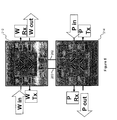
- FIG. 5 An alternative embodiment of a 2x2 optical switch is shown in figure 5, which is implemented using MEMS (micro electro mechanical systems) technology.
- the switching is performed utilising mirrors (231,232,233,234 and 241,242,243,244).
- the mirrors are controlled such that they are either in an upright position (as shown in the plan view illustrated by figure 5) or alternatively flat against the MEMS chip surface (i.e. lying in the plane of the paper) in which case they are out of the optical path.
- the switch 210 comprises a working card 212 and a protect card 214.
- Each card has a respective transmitter input (Tx), receiver output (Rx), and transmission line input and output (IN,OUT).
- Tx transmitter input
- Rx receiver output
- IN,OUT transmission line input and output
- each of the respective inputs and outputs are connected to a lens assembly 250 to ensure accurate collimation of the free space optical beam as a signal enters a card 212,214, and accurate. Focussing of the beam into the relevant fibre as the signal leaves the cards.
- the two cards are connected by two waveguides in the form of optical fibres 260,262. These fibres are removably attached to either one or both of the working and protect cards 212,214. It will be appreciated that in this instance only two fibres are required to propagate optical signals between the two cards, whilst in the previous embodiment four fibres were required.
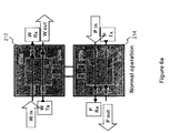
- FIG. 6a shows a typical "normal operation" of the switch, in which all of the mirrors 231-4,244-4 lie flat against the MEM chip surface. Consequently, each of the cards 212,214 act as pass through devices.
- the optical signal from the working channel (Win) is propagated along the free space path 272a to the working receiver, the signal from the working transmitter propagates along the free space path 274a to the working channel output, the protect channel signal propagating along path 276a to the protect receiver, and the signal from the protect transmitter propagating along path 278a to the protect channel output.
- Figure 6b shows an alternative state of the switch in which mirrors 231,234,241,244 are in the upright position. Consequently the working optical channels are connected to the protect transmitter and receiver via the optical path 272b and 274b.
- a signal from the working channel Win will enter the working card 212, be collimated from the fibre into a free space beam 272b by a lens assembly, reflect off mirror 231, then be forwarded into fibre 260 by a further lens assembly.
- the signal will then be transmitted along fibre 260 to the protect card 214, pass through a further lens assembly for collimation into another free space beam, reflect from mirror 241 into a further lens assembly which will focus the beam into the fibre for transmission to the protect receiver P RX .
- Figure 6c shows another state of the switch in which mirrors 233,232,243,242 are in the upright position.
- the protect optical channels are hence connected to the working transmitter and receiver via the optical path 278c and 276c.
- the switch could be implemented using polymer waveguide, mach zehnder, LC (liquid crystal), and/or a variety of MEMS switching technologies.
- LC liquid crystal
- Such an LC switch is manufactured by SpectraSwitch of Santa Rosa, California, USA and Chorum Technologies, Inc of Richardson, Texas, USA.
- optical and “light should be understood as pertaining not only to the visible part of the electromagnetic spectrum, but also to the infra-red and ultra-violet parts that bound the visible part.
Landscapes
- Engineering & Computer Science (AREA)
- Computer Networks & Wireless Communication (AREA)
- Use Of Switch Circuits For Exchanges And Methods Of Control Of Multiplex Exchanges (AREA)
- Optical Communication System (AREA)
- Mechanical Light Control Or Optical Switches (AREA)
Abstract
Description
- The present invention relates to an optical switch, and in particular to a distributed optical switch.
- Many industries utilise optical switches in their equipment. For instance, the telecommunications industry utilises optical switches in optical dedicated protection and optical shared protection rings (OSPR's). Optical transmission systems are often constructed with a fault recovery mechanism so that if there is a complete loss of transmission capability due to component and/or transmission line failure, the traffic can be reallocated to other physically diverse routes. Pending US application no. 09/349,349 (incorporated herein by reference) describes such an OSPR system.
- Switches are commonly incorporated in OSPR's at network nodes. At a network node, a 2x2 switch may be utilised to connect between working and protect transmitters/receivers and working and protect transmission lines. Although the OSPR is designed with a fault recovery mechanism, performance of the node will be seriously affected if a switch fails, or has to be removed for maintenance or in order to be replaced. In such an instance, switch failure maintenance can interrupt both working and protection traffic.
- Figure 1 shows a working (2) and protect (4) transmission line connected to respective working and protect receivers (6,8) via a 2x2 switch (10). Similarly, the working and protect transmission lines (2',4') may be connected to the working and protect transmitters (6',8') via a 2x2 switch (10'). Alternatively, a bi-directional 2x2 switch and a combination transmitter/receiver can be used before the outgoing and incoming paths are routed to transmitter and receiver respectively. This allows these two switches to be combined into one (not shown).
- A 2x2 switch allows independent connection of working and protection optical channels (or transmission lines) to working or protection receiver or transmitter as appropriate. This functionality is required in both 1+1 (in which the same data is simultaneously transmitted along both the working and protection lines, providing redundancy in the event of either of the lines failing) and 1:1 protection switching (in which high priority data is typically transmitted along the working line, low priority data along the protect line; in the event of the working line failing, the high priority data is routed along the protect line).
- Figure 2 shows how such bi-directional 2x2 switches may be incorporated into an
OSPR module 20, which includes an optical cross connect (oxc) 22. The OXC contains optical switches to route traffic off and on the shared protection as described in US application no. 09/349,349. An OSPR will be comprised of a number of such modules or nodes. - The above description is merely an example of how such an optical switch can be used. Many systems, not limited to telecommunications may utilise such optical switching arrangements. The failure of a switch, or a part of the switch, inevitably affects connectivity between the inputs and outputs, as does removal of the switch for repair or maintenance. The present invention aims to address some of the problems of the prior art.
- In a first aspect, the present invention provides an optical switching segment comprising at least one input, at least one output, at least one connector arranged to be connectable to a further segment so as to provide at least one of a further input and a further output, and a switch arranged to selectively connect between two of said input, said output and said connector. Thus, such a segment could be installed in a network as part of an optical switch that is distributed; thus failure of any one segment, or its removal, need not affect all of the connectivity of the switch.
- Preferably, said connector provides a further input and said switch is arranged to selectively connect said output to one of said input or said connector.
- Alternatively, said connector provides a further output and said switch is arranged to selectively connect said input to one of said output and said connector.
- In another aspect, the present invention provides an optical switch comprising at least two segments, each segment having a respective input and a respective output, arranged such that in use if a first segment is removed, a second segment can operate as a pass-through device.
- In a further aspect, the present invention provides an optical switch distributed over at least two cards, the first card having a first input and a first output, and the second card having at least one of a second input and a second output, the switch further comprising a switching means arranged to selectively form a connection between two of said first input, said first output, and said second input and output, arranged such that said second card may be removed from communication with said first card whilst the switch is in use, said first card then being arranged to connect said first input to said first output.
- Preferably, said cards are removably attached. Alternatively, detachment of the cards may require destruction or damage to one or more of any components that connect the cards, e.g. the cutting of an optical fibre connection.
- Preferably, connecting means between the cards comprises at least one of a freespace optical beam path and a waveguide.
- Preferably, said switching means comprises a selection from the group of polymer waveguides, mach-zehnders and MEMS (micro-electro mechanical systems).
- Preferably, said switching means utilises the control of a selection from the group of reflection, refraction and diffraction to perform the switching.
- The switch may further comprise a port for providing control signals to said switch.
- In another aspect, the present invention provides a telecommunications system comprising a switch as claimed in claim 4.
- Preferably, said switch is connected to a system, the respective inputs and outputs being selectively coupled together as required by an operator.
- Preferably, a first portion of the switch is arranged to act as a pass-through device if a second portion of the switch is removed from the system.
- In order to show how the invention may be carried into effect, embodiments of the invention are now described below by way of example only and with reference to the accompanying figures in which:-
- FIGURE 1 illustrates the typical connections of a 2x2 switch in an OSPR node (PRIOR ART);
- FIGURE 2 illustrates an OSPR module (PRIOR ART);
- FIGURE 3 illustrates a 2x2 switch according to an embodiment of the present invention;
- FIGURE 4 illustrates how the OSPR shown in figure 2 can be implemented utilising two of the switches shown in figure 3;
- FIGURE 5 illustrates a 2x2 switch in accordance with an alternative embodiment of the present invention;
- FIGURE 6a illustrates the normal operation of the switch shown in figure 5;
- FIGURE 6b illustrates a configuration of the switch shown in figure 5 in which the working optical channels are connected to the protect transmitter and receiver; and
- FIGURE 6c illustrates a configuration of the switch shown in figure 5 in which the protect optical channels are connected to the working transmitter and receiver.
-
- Figure 3 illustrates a
2x2 switch 110 comprising two cards 112,114. For convenience, to indicate their functionality within an OSPR module, the two cards have been labelled as aworking card 112 and aprotect card 114. - The
switch 110 is implemented utilising a combination of splitters 131,132,133,134 and 1x2 switches 141,142,143,143,144. If desired, each splitter could be replaced by a single 1x2 switch. - In the current implementation, each splitter 131,132,133,134 is connected to two 1x2 switches 141,142,143,143,144 via an optical waveguide such as optical fibre a,b,c,d,e,f,g,h. This particular embodiment relates to a unidirectional system, with the arrow heads in the diagram being indicative of the direction in which the optical signals would be transmitted.
- A
connector 150 is used to connect the optical fibres of the working card to the respective optical fibres of the protect card, i.e. a is connected to a', b is connected to b', c is connected to c', and d is connected to d'. The connection between each of these fibres is removable. This facilitates easy separation of the cards. - It will be appreciated that the switching function of the switch shown in figure 3 is the same as the 2x2 switches of the prior art. In the configuration shown, WTx (the working transmitter) can send a signal via the
splitter 131 to bothswitch 142 via optical fibre e or via optical fibre d,d' to switch 143. It will therefore be appreciated that via appropriate control of theswitches - As the two cards 112,114 are removably attached via connector 150 (with any other connecting means between the two cards also being removably attached), either card can be removed. Traffic can then still flow through either the working or the protection optical channel, i.e. with the retained card acting as a pass through device. It will therefore be appreciated that any single component within the switch can fail, and traffic may still flow through either the working or protection channel. Alternatively, either card may be removed for maintenance or repair, with the remaining card acting as a pass through device to permit traffic to flow through the remaining channel.
- Figure 4 shows how two such cards may be implemented in an OSPR module. As can be seen, the appropriate protect card inputs and outputs are connected directly to the optical cross connect (OXC).
- An alternative embodiment of a 2x2 optical switch is shown in figure 5, which is implemented using MEMS (micro electro mechanical systems) technology. In this particular instance, the switching is performed utilising mirrors (231,232,233,234 and 241,242,243,244). The mirrors are controlled such that they are either in an upright position (as shown in the plan view illustrated by figure 5) or alternatively flat against the MEMS chip surface (i.e. lying in the plane of the paper) in which case they are out of the optical path.
- An example of such a switch is described in "Free-Space Micromachined Optical Switches for Optical Networking", F Y Lin, E L Goldstein and R W Tkach, IEEE Journal of Selected Topics in Quantum Electronics, Vol. 5, No. 1, January/ February 1999.
- The switch 210 comprises a working
card 212 and aprotect card 214. Each card has a respective transmitter input (Tx), receiver output (Rx), and transmission line input and output (IN,OUT). In this particular embodiment, each of the respective inputs and outputs are connected to alens assembly 250 to ensure accurate collimation of the free space optical beam as a signal enters a card 212,214, and accurate. Focussing of the beam into the relevant fibre as the signal leaves the cards. - In this embodiment, the two cards are connected by two waveguides in the form of optical fibres 260,262. These fibres are removably attached to either one or both of the working and protect cards 212,214. It will be appreciated that in this instance only two fibres are required to propagate optical signals between the two cards, whilst in the previous embodiment four fibres were required.
- Operation of such a 2x2 switch is shown in figures 6a to 6c. Figure 6a shows a typical "normal operation" of the switch, in which all of the mirrors 231-4,244-4 lie flat against the MEM chip surface. Consequently, each of the cards 212,214 act as pass through devices. The optical signal from the working channel (Win) is propagated along the
free space path 272a to the working receiver, the signal from the working transmitter propagates along thefree space path 274a to the working channel output, the protect channel signal propagating along path 276a to the protect receiver, and the signal from the protect transmitter propagating alongpath 278a to the protect channel output. - If either card 212,214 is removed from the system in which such a switch is installed, it will be appreciated that the remaining card may continue to act as a pass through device.
- Figure 6b shows an alternative state of the switch in which mirrors 231,234,241,244 are in the upright position. Consequently the working optical channels are connected to the protect transmitter and receiver via the
optical path card 212, be collimated from the fibre into afree space beam 272b by a lens assembly, reflect off mirror 231, then be forwarded intofibre 260 by a further lens assembly. The signal will then be transmitted alongfibre 260 to theprotect card 214, pass through a further lens assembly for collimation into another free space beam, reflect from mirror 241 into a further lens assembly which will focus the beam into the fibre for transmission to the protect receiver PRX. - Figure 6c shows another state of the switch in which mirrors 233,232,243,242 are in the upright position. The protect optical channels are hence connected to the working transmitter and receiver via the
optical path - Whilst the preferred embodiments have described specific implementations of the invention, it will be appreciated that the invention may be implemented utilising a variety of alternate optical switching configurations and/or technologies.
- For instance, the switch could be implemented using polymer waveguide, mach zehnder, LC (liquid crystal), and/or a variety of MEMS switching technologies. Such an LC switch is manufactured by SpectraSwitch of Santa Rosa, California, USA and Chorum Technologies, Inc of Richardson, Texas, USA.
- For the purposes of this specification, the terms "optical" and "light should be understood as pertaining not only to the visible part of the electromagnetic spectrum, but also to the infra-red and ultra-violet parts that bound the visible part.
- Any range or device given herein may be extended or altered without losing the effect sought, as will be apparent to a skilled person from an understanding of the teaching herein. For instance, whilst the present invention has been described in relation to 2x2 switches, it will be appreciated that the invention can result in an NxM switch, arranged over two or more cards or portions, where N and M are both integers greater than 2. Equally, whilst the present invention has been illustrated by describing unidirectional 2x2 switches for bi-directional optical signals.
Claims (13)
- An optical switching segment comprising at least one input, at least one output, at least one connector arranged to be connectable to a further segment so as to provide at least one of a further input and a further output, and a switch arranged to selectively connect between two of said input, said output and said connector.
- A switching segment as claimed in claim 1, wherein said connector provides a further input and said switch is arranged to selectively connect said output to one of said input or said connector.
- A switching segment as claimed in claim 1 or claim 2, wherein said connector provides a further output and said switch is arranged to selectively connect said input to one of said output and said connector.
- An optical switch comprising at least two segments, each segment having a respective input and a respective output, arranged such that in use if a first segment is removed, a second segment can operate as a pass-through device.
- An optical switch distributed over at least two cards, the first card having a first input and a first output, and the second card having at least one of a second input and a second output, the switch further comprising a switching means arranged to selectively form a connection between two of said first input, said first output, and said second input and output, arranged such that said second card may be removed from communication with said first card whilst the switch is in use, said first card then being arranged to connect said first input to said first output.
- A switch as claimed in claim 5, wherein said cards are removably attached.
- A switch as claimed in claim 5 or claim 6, wherein connecting means between the cards comprises at least one of a freespace optical beam path and a waveguide.
- A switch as claimed in any of claims 5 to 7, wherein said switching means comprises a selection from the group of
polymer waveguides, mach-zehnders and MEM's (micro-electro mechanical systems). - A switch as claimed in any of claims 5 to 8, wherein said switching means utilises the control of a selection from the group of reflection, refraction and diffraction to perform the switching.
- A switch as claimed in any of claims 5 to 9, further comprising a port for providing control signals to said switch.
- A telecommunications system comprising an optical switch comprising at least two segments, each segment having a respective input and a respective output, arranged such that in use if a first segment is removed, a second segment can operate as a pass-through device.
- A method of operating an optical switch comprising at least two segments, each segment having a respective input and a respective output, arranged such that in use if a first segment is removed, a second segment can operate as a pass-through device, wherein said switch is connected to a system, said respective inputs and outputs being selectively coupled together as required by an operator.
- A method as claimed in claim 12, wherein a first portion of the switch is arranged to act as a pass-through device if a second portion of the switch is removed from the system.
Applications Claiming Priority (2)
| Application Number | Priority Date | Filing Date | Title |
|---|---|---|---|
| US09/470,630 US6396969B1 (en) | 1999-12-22 | 1999-12-22 | Distributed optical switching device |
| US470630 | 1999-12-22 |
Publications (3)
| Publication Number | Publication Date |
|---|---|
| EP1111954A2 true EP1111954A2 (en) | 2001-06-27 |
| EP1111954A3 EP1111954A3 (en) | 2003-11-12 |
| EP1111954B1 EP1111954B1 (en) | 2010-10-06 |
Family
ID=23868362
Family Applications (1)
| Application Number | Title | Priority Date | Filing Date |
|---|---|---|---|
| EP00310721A Expired - Lifetime EP1111954B1 (en) | 1999-12-22 | 2000-12-01 | Distributed optical switching device |
Country Status (4)
| Country | Link |
|---|---|
| US (1) | US6396969B1 (en) |
| EP (1) | EP1111954B1 (en) |
| CA (1) | CA2328534C (en) |
| DE (1) | DE60045065D1 (en) |
Cited By (2)
| Publication number | Priority date | Publication date | Assignee | Title |
|---|---|---|---|---|
| FR2906045A1 (en) * | 2006-09-20 | 2008-03-21 | Alcatel Sa | Optical wavelength processing module e.g. wavelength selector switch, wavelength static relay, controlling method for optical transparent or photonic switching node, involves producing signals for configuring module in state for channel |
| DE112005000732T5 (en) | 2004-03-25 | 2008-09-04 | Merck Patent Gmbh | Liquid crystal compounds, liquid crystal medium and liquid crystal display |
Families Citing this family (8)
| Publication number | Priority date | Publication date | Assignee | Title |
|---|---|---|---|---|
| US6623186B2 (en) * | 2001-04-26 | 2003-09-23 | Occam Networks | Optical ethernet overlay for loop topology network |
| US6563979B2 (en) * | 2001-06-22 | 2003-05-13 | Dorsal Networks, Inc. | Automatically switched redundant switch configurations |
| US20040105136A1 (en) * | 2001-05-08 | 2004-06-03 | Corvis Corporation | Interconnections and protection between optical communications networks |
| TW200827797A (en) * | 2006-12-20 | 2008-07-01 | Inventec Multimedia & Telecom | Switching device of light-beam channel of optical fiber network |
| TW200827799A (en) * | 2006-12-20 | 2008-07-01 | Inventec Multimedia & Telecom | Switching device of light-beam channel of optical fiber network |
| EP2536166A1 (en) * | 2011-06-14 | 2012-12-19 | Siemens Aktiengesellschaft | Signal path control device |
| US10735125B2 (en) * | 2017-09-30 | 2020-08-04 | Juniper Networks, Inc. | Optical multicast switch with broadcast capability |
| US12176945B2 (en) * | 2022-06-14 | 2024-12-24 | Mellanox Technologies, Ltd. | Transceiver module |
Citations (3)
| Publication number | Priority date | Publication date | Assignee | Title |
|---|---|---|---|---|
| US5739935A (en) | 1995-11-14 | 1998-04-14 | Telefonaktiebolaget Lm Ericsson | Modular optical cross-connect architecture with optical wavelength switching |
| EP0898440A2 (en) | 1997-08-21 | 1999-02-24 | Jds Fitel Inc. | Optical switch module |
| US6643464B1 (en) | 1999-07-07 | 2003-11-04 | Nortel Networks Limited | Constrained optical mesh protection for transmission systems |
Family Cites Families (4)
| Publication number | Priority date | Publication date | Assignee | Title |
|---|---|---|---|---|
| US5241610A (en) * | 1991-09-03 | 1993-08-31 | Scientific-Atlanta, Inc. | Optical switching in a fiber communication system and method using same |
| US5515361A (en) * | 1995-02-24 | 1996-05-07 | International Business Machines Corporation | Link monitoring and management in optical star networks |
| NL1001841C2 (en) * | 1995-12-07 | 1997-06-10 | Nederland Ptt | Optical coupling device and optical switch for use in the optical coupling device. |
| JPH10173598A (en) * | 1996-12-09 | 1998-06-26 | Fujitsu Ltd | Optical multiplexer / demultiplexer and optical transmission system using the same |
-
1999
- 1999-12-22 US US09/470,630 patent/US6396969B1/en not_active Expired - Lifetime
-
2000
- 2000-12-01 DE DE60045065T patent/DE60045065D1/en not_active Expired - Lifetime
- 2000-12-01 EP EP00310721A patent/EP1111954B1/en not_active Expired - Lifetime
- 2000-12-13 CA CA2328534A patent/CA2328534C/en not_active Expired - Fee Related
Patent Citations (3)
| Publication number | Priority date | Publication date | Assignee | Title |
|---|---|---|---|---|
| US5739935A (en) | 1995-11-14 | 1998-04-14 | Telefonaktiebolaget Lm Ericsson | Modular optical cross-connect architecture with optical wavelength switching |
| EP0898440A2 (en) | 1997-08-21 | 1999-02-24 | Jds Fitel Inc. | Optical switch module |
| US6643464B1 (en) | 1999-07-07 | 2003-11-04 | Nortel Networks Limited | Constrained optical mesh protection for transmission systems |
Cited By (3)
| Publication number | Priority date | Publication date | Assignee | Title |
|---|---|---|---|---|
| DE112005000732T5 (en) | 2004-03-25 | 2008-09-04 | Merck Patent Gmbh | Liquid crystal compounds, liquid crystal medium and liquid crystal display |
| FR2906045A1 (en) * | 2006-09-20 | 2008-03-21 | Alcatel Sa | Optical wavelength processing module e.g. wavelength selector switch, wavelength static relay, controlling method for optical transparent or photonic switching node, involves producing signals for configuring module in state for channel |
| EP1906574A1 (en) * | 2006-09-20 | 2008-04-02 | Alcatel Lucent | Control method for a shared protection module and device for processing optical wavelengths |
Also Published As
| Publication number | Publication date |
|---|---|
| CA2328534C (en) | 2010-02-16 |
| CA2328534A1 (en) | 2001-06-22 |
| US6396969B1 (en) | 2002-05-28 |
| EP1111954A3 (en) | 2003-11-12 |
| DE60045065D1 (en) | 2010-11-18 |
| EP1111954B1 (en) | 2010-10-06 |
Similar Documents
| Publication | Publication Date | Title |
|---|---|---|
| CA2318080C (en) | Wavelength-selective optical add/drop using tilting micro-mirrors | |
| CA2392704C (en) | System and method of optical switching | |
| US6344911B1 (en) | Upgradable optical communication system module | |
| US6631222B1 (en) | Reconfigurable optical switch | |
| EP3916445B1 (en) | Core selection switch and optical node device | |
| KR20030083742A (en) | Method and apparatus for transferring wdm signals between different wdm communications systems in optically transparent manner | |
| EP1016235A2 (en) | Wavelength-selective optical switching apparatus | |
| CA2655746A1 (en) | Optical communication system | |
| JPH10112700A (en) | Wavelength division multiplexing optical transmission equipment with ring configuration | |
| CA2328534C (en) | Distributed optical switching device | |
| US6219474B1 (en) | Configurable optical add/drop device | |
| US20040212897A1 (en) | Configurable wavelength routing device | |
| EP1064739B1 (en) | Protection of wdm-channels | |
| US6289148B1 (en) | Free-space micro-mirror wavelength add/drop multiplexers with full connectivity for two-fiber ring networks | |
| US8081875B2 (en) | Wavelength switch | |
| Helkey et al. | Design of large, MEMS-based photonic switches | |
| US6594412B2 (en) | Optical add/drop device | |
| WO2002095467A2 (en) | Reconfigurable optical add/drop module | |
| US6922530B1 (en) | Method and apparatus for optical channel switching in an optical add/drop multiplexer | |
| US6782201B2 (en) | Four fiber ring network optical switching circuit using branched inputs | |
| US7194206B2 (en) | Variable-density optical cross-connect architectures and upgrades | |
| US6594413B2 (en) | Optical switching device | |
| CA2267779A1 (en) | Method and apparatus for combining add/drop optical signal lines from a plurality of branching units | |
| WO2001067136A2 (en) | A ring interconnection architecture | |
| MXPA00002816A (en) | Wavelength-selective optical switching apparatus, optical communications apparatus using the same, and method for use in the optical communications apparatus |
Legal Events
| Date | Code | Title | Description |
|---|---|---|---|
| PUAI | Public reference made under article 153(3) epc to a published international application that has entered the european phase |
Free format text: ORIGINAL CODE: 0009012 |
|
| AK | Designated contracting states |
Kind code of ref document: A2 Designated state(s): AT BE CH CY DE DK ES FI FR GB GR IE IT LI LU MC NL PT SE TR |
|
| AX | Request for extension of the european patent |
Free format text: AL;LT;LV;MK;RO;SI |
|
| PUAL | Search report despatched |
Free format text: ORIGINAL CODE: 0009013 |
|
| RAP1 | Party data changed (applicant data changed or rights of an application transferred) |
Owner name: NORTEL NETWORKS LIMITED |
|
| AK | Designated contracting states |
Kind code of ref document: A3 Designated state(s): AT BE CH CY DE DK ES FI FR GB GR IE IT LI LU MC NL PT SE TR |
|
| AX | Request for extension of the european patent |
Extension state: AL LT LV MK RO SI |
|
| 17P | Request for examination filed |
Effective date: 20040512 |
|
| AKX | Designation fees paid |
Designated state(s): DE FR GB IT |
|
| 17Q | First examination report despatched |
Effective date: 20050503 |
|
| GRAP | Despatch of communication of intention to grant a patent |
Free format text: ORIGINAL CODE: EPIDOSNIGR1 |
|
| GRAS | Grant fee paid |
Free format text: ORIGINAL CODE: EPIDOSNIGR3 |
|
| GRAA | (expected) grant |
Free format text: ORIGINAL CODE: 0009210 |
|
| AK | Designated contracting states |
Kind code of ref document: B1 Designated state(s): DE FR GB IT |
|
| REG | Reference to a national code |
Ref country code: GB Ref legal event code: FG4D |
|
| REF | Corresponds to: |
Ref document number: 60045065 Country of ref document: DE Date of ref document: 20101118 Kind code of ref document: P |
|
| PLBE | No opposition filed within time limit |
Free format text: ORIGINAL CODE: 0009261 |
|
| STAA | Information on the status of an ep patent application or granted ep patent |
Free format text: STATUS: NO OPPOSITION FILED WITHIN TIME LIMIT |
|
| 26N | No opposition filed |
Effective date: 20110707 |
|
| REG | Reference to a national code |
Ref country code: DE Ref legal event code: R097 Ref document number: 60045065 Country of ref document: DE Effective date: 20110707 |
|
| PG25 | Lapsed in a contracting state [announced via postgrant information from national office to epo] |
Ref country code: IT Free format text: LAPSE BECAUSE OF FAILURE TO SUBMIT A TRANSLATION OF THE DESCRIPTION OR TO PAY THE FEE WITHIN THE PRESCRIBED TIME-LIMIT Effective date: 20101006 |
|
| PGFP | Annual fee paid to national office [announced via postgrant information from national office to epo] |
Ref country code: GB Payment date: 20141124 Year of fee payment: 15 |
|
| PGFP | Annual fee paid to national office [announced via postgrant information from national office to epo] |
Ref country code: FR Payment date: 20141124 Year of fee payment: 15 |
|
| PGFP | Annual fee paid to national office [announced via postgrant information from national office to epo] |
Ref country code: DE Payment date: 20141222 Year of fee payment: 15 |
|
| REG | Reference to a national code |
Ref country code: DE Ref legal event code: R119 Ref document number: 60045065 Country of ref document: DE |
|
| GBPC | Gb: european patent ceased through non-payment of renewal fee |
Effective date: 20151201 |
|
| REG | Reference to a national code |
Ref country code: FR Ref legal event code: ST Effective date: 20160831 |
|
| PG25 | Lapsed in a contracting state [announced via postgrant information from national office to epo] |
Ref country code: DE Free format text: LAPSE BECAUSE OF NON-PAYMENT OF DUE FEES Effective date: 20160701 Ref country code: GB Free format text: LAPSE BECAUSE OF NON-PAYMENT OF DUE FEES Effective date: 20151201 |
|
| PG25 | Lapsed in a contracting state [announced via postgrant information from national office to epo] |
Ref country code: FR Free format text: LAPSE BECAUSE OF NON-PAYMENT OF DUE FEES Effective date: 20151231 |