EP1111861B1 - Methods and devices providing wireless access to computer networks - Google Patents
Methods and devices providing wireless access to computer networks Download PDFInfo
- Publication number
- EP1111861B1 EP1111861B1 EP00403663A EP00403663A EP1111861B1 EP 1111861 B1 EP1111861 B1 EP 1111861B1 EP 00403663 A EP00403663 A EP 00403663A EP 00403663 A EP00403663 A EP 00403663A EP 1111861 B1 EP1111861 B1 EP 1111861B1
- Authority
- EP
- European Patent Office
- Prior art keywords
- address
- access point
- network
- terminal
- wireless
- Prior art date
- Legal status (The legal status is an assumption and is not a legal conclusion. Google has not performed a legal analysis and makes no representation as to the accuracy of the status listed.)
- Expired - Lifetime
Links
- 238000000034 method Methods 0.000 title claims abstract description 24
- 238000001914 filtration Methods 0.000 claims description 32
- 230000000694 effects Effects 0.000 claims description 9
- 238000004590 computer program Methods 0.000 claims description 6
- 230000001960 triggered effect Effects 0.000 claims 1
- 230000015654 memory Effects 0.000 abstract description 16
- 230000005540 biological transmission Effects 0.000 abstract description 13
- 238000012360 testing method Methods 0.000 description 29
- 238000012545 processing Methods 0.000 description 18
- 230000006870 function Effects 0.000 description 14
- 238000004891 communication Methods 0.000 description 12
- 238000010586 diagram Methods 0.000 description 12
- 230000008859 change Effects 0.000 description 10
- 230000008901 benefit Effects 0.000 description 6
- 238000012986 modification Methods 0.000 description 5
- 230000004048 modification Effects 0.000 description 5
- 230000004913 activation Effects 0.000 description 3
- 230000009849 deactivation Effects 0.000 description 3
- 238000005516 engineering process Methods 0.000 description 3
- 230000010365 information processing Effects 0.000 description 3
- 230000009467 reduction Effects 0.000 description 3
- 230000004044 response Effects 0.000 description 3
- 238000011161 development Methods 0.000 description 2
- 230000006978 adaptation Effects 0.000 description 1
- 238000012937 correction Methods 0.000 description 1
- 238000013461 design Methods 0.000 description 1
- 238000007429 general method Methods 0.000 description 1
- 238000005304 joining Methods 0.000 description 1
- 238000004519 manufacturing process Methods 0.000 description 1
- 230000011664 signaling Effects 0.000 description 1
- 238000003860 storage Methods 0.000 description 1
- 238000012546 transfer Methods 0.000 description 1
Images





Classifications
-
- H—ELECTRICITY
- H04—ELECTRIC COMMUNICATION TECHNIQUE
- H04W—WIRELESS COMMUNICATION NETWORKS
- H04W92/00—Interfaces specially adapted for wireless communication networks
- H04W92/02—Inter-networking arrangements
-
- H—ELECTRICITY
- H04—ELECTRIC COMMUNICATION TECHNIQUE
- H04W—WIRELESS COMMUNICATION NETWORKS
- H04W40/00—Communication routing or communication path finding
- H04W40/02—Communication route or path selection, e.g. power-based or shortest path routing
-
- H—ELECTRICITY
- H04—ELECTRIC COMMUNICATION TECHNIQUE
- H04W—WIRELESS COMMUNICATION NETWORKS
- H04W8/00—Network data management
- H04W8/26—Network addressing or numbering for mobility support
-
- H—ELECTRICITY
- H04—ELECTRIC COMMUNICATION TECHNIQUE
- H04W—WIRELESS COMMUNICATION NETWORKS
- H04W88/00—Devices specially adapted for wireless communication networks, e.g. terminals, base stations or access point devices
- H04W88/08—Access point devices
-
- H—ELECTRICITY
- H04—ELECTRIC COMMUNICATION TECHNIQUE
- H04W—WIRELESS COMMUNICATION NETWORKS
- H04W88/00—Devices specially adapted for wireless communication networks, e.g. terminals, base stations or access point devices
- H04W88/16—Gateway arrangements
Definitions
- the present invention relates to methods and devices for transmitting data packets in a telecommunications network, and to systems, information storage means and computer programs corresponding to them.
- the invention is effectively adopted in the field of the interconnection of wireless networks with cabled networks.
- the invention is described in its application to the learning of the MAC (" Medium Access Control ") address for a wireless point of access and a wireless terminal adaptor.
- MAC Medium Access Control
- DECT Digital Enhanced Cordless Telecommunications
- the access point When a source station, situated in the wireless network, transmits a data packet to the cabled network, the access point saves the source address of the packet. This saving of the source address is done for each packet received from a wireless terminal through the access point.
- This method has the drawback of consuming a substantially large radio bandwidth and is in particular adapted to an environment where the wireless equipment items are very mobile.
- the invention concerns the filtering of data packets from a first telecommunications network to a second telecommunications network.
- the apparatus effecting the bridge between the two networks and fulfilling the filtering function is referred to as the access point.
- the data packets include the network address of the transmitting device, referred to as the source address, and the network address of the receiving device, referred to as the destination address.
- the invention applies to the situation where a single terminal, having an address compatible with the first network, is accessible from the first network by means of the second network.
- a first terminal of a cabled network may be accessible through a second terminal of the cable network only by passing through a wireless telecommunications network, to which the first terminal is connected by means of a wireless terminal adaptor.
- the bridge In the field of the interconnection of local networks, it is well known to use a bridge between two networks.
- the bridge generally functions by means of a specific memory, which contains the table of addresses of the first network.
- the bridge For each packet coming from this network, the bridge generally compares the destination address with the addresses contained in the table. If the destination address corresponds to an address contained in the table, this means that the packet is intended for a terminal of the first network and the packet is not transmitted to the second network. In the contrary case, this means that the packet may be intended for a terminal in the second network; it is therefore transmitted to this second network.
- the document US-A-5 959 976 makes it possible to reduce the memory capacity of the table of addresses, keeping only a flag equal to 0 or 1 in place of the complete address.
- the document US-A-5 396 493 proposes to relieve the main processor of the comparison of the addresses, allocating this task to the network controller, again by means of a table.
- the access point is a bridge between a local network and a wireless network composed of terminal adaptors.
- the radio address of the terminal is allocated to the address of the adaptor to which it is connected.
- the adaptor can filter, at a wireless link, the packets intended for the terminal.
- such a system has the drawback of representing a load for the wireless network.
- the purpose of the present invention is to remedy the above drawbacks.
- this invention proposes a method of filtering data packets according to claim 1 and an access point according to claim 3.
- Other features are recited in the subclaims.
- the invention has many advantages, notably:
- the invention optimises the processing time for a packet received over the radio port of a wireless access point for learning the source address, in order to effect a filtering function.
- the invention makes it possible, in a wireless network, to filter the data coming from a cabled network with a higher transmission rate and is adapted to a system where the access point on the cabled network is intended to communicate with wireless terminal adaptors, to which only one item of network termination equipment can be connected, for example a printer, a computer or a digital copier.
- the present invention makes it possible to reduce the processing time for each packet, by reading the source address of an item of equipment connected to the wireless network, not for each packet, but only when this is necessary, that is to say when an item of equipment in the wireless network is likely to have been changed. This allows to improve the performance of the whole of the system.
- This invention makes it possible to dispense with the use of electronic components or additional memories for the filtering function, and therefore to reduce the development and manufacturing costs. This is because, on the one hand, the invention uses no additional memory, since the address to be filtered is allocated to the address proper of the network controller of the access point and, on the other hand, the invention does not require the use of a complex controller provided with functions for the filtering of several addresses.
- the access point with the address of the terminal is "transparent" seen from the first network.
- the invention makes it possible to completely effect the filtering at the access point, which reduces the load on the wireless network.
- the terminal whose network address it is sought to filter is for example a printer or computer or digital copier connected to a local network by means of a specific link such as a radio or infrared connection.
- the invention also has other advantages, notabiy:
- the invention also relates to a computer readable medium according to claim 4, microprocessor storing instructions of a computer program, making it possible and wich may be partially or totally removable.
- the invention also relates to a computer program according to claim 6.
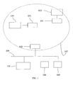
- Figure 1 depicts a wireless local network 107 which can be interconnected to a cabled local network 104 by means of a wireless access point 102.
- the wireless local network 107 consists of several items of terminal equipment 100, 103 having a communication interface with the network.
- the terminals 100 and 103 are digital copiers provided with an Ethernet interface.
- the context of a cabled network of the Ethernet type is given by way of in no way limitative example; the invention applies just as well to the interconnection with any other type of cabled network, for example a network of the token ring type.
- Each terminal is connected to the wireless local network by means of a wireless terminal adaptor 101, possibly integrated into the terminal.
- a terminal adaptor makes it possible to connect one and only one terminal.
- the wireless terminal adaptor is connected to the terminal by an interface of the 10 or 100 base T (Ethernet) type.
- the number of adaptors of the wireless local network terminal is limited by the capacity of the wireless access point.
- the number of terminal adaptors 101 supported by the access point 102 is limited to one.
- the wireless communication between the access point 102 and the wireless terminal adaptors 101 uses the DECT digital radio communication technology specified by the ETSI, EN 300 175, 1991.
- the cabled local network 104 is a network of the Ethernet type having a transmission rate of 10 and/or 100 Mbit/s.
- the items of equipment 105, 106 and 108 are terminals connected to the cabled network 104.
- the terminal 105 is a print server and the terminals 106 and 108 are computers.
- the DECT radio technology makes it possible to achieve a maximum transmission rate of 552 kbit/s whilst the transmission rate of the cabled network can attain 100 Mbit/s.
- the wireless access point 102 cannot therefore transfer over the radio medium all the data circulating on the cabled network without risk of unnecessarily loading the radio link or even losing data. It is necessary to filter the data packets coming from the cabled network before transmitting them over the wireless network. Only the packets intended for the wireless network terminals 100, 103 must be transferred over the radio medium.
- the packets are filtered at level 2 of the OSI (" Open Systems Interconnection ") model layer, that is to say at the level of the MAC (" Medium Access Control ”) layer of the Ethernet network.
- OSI Open Systems Interconnection
- MAC Medium Access Control
- Figure 2 depicts the structure of an Ethernet MAC data frame designated by the reference 200 in the drawing (defined by IEEE 802.3).
- This frame is composed of several fields.
- the first two fields 201 and 202 are particularly useful.
- the field “DA” 201 contains the MAC destination address of the packet, in 6 bytes.
- the field “SA” 202 contains the MAC source address, or original address of the packet, in 6 bytes.
- the field “L” contains the length of the data contained in the frame, in 2 bytes.
- the field “Info” contains the data proper, in a number of bytes which can vary from 0 to 1500.
- the field “Pad” contains binary padding elements, in 46 bytes at a maximum, so that the total number of bytes contained in the fields "DA”, “SA”, “L”, “Pad” and “FCS” is equal to 64.
- the field “FCS” (“ Frame Check Sequence ”) contains a check sequence allowing to detect transmission errors.
- the access point When the access point receives, from the cabled network 104, a data packet whose destination address 201 corresponds to the MAC address of one of the communication terminals 100 or 103 of the wireless network 107, this packet must then be transmitted over the radio medium. On the other hand, when the access point receives a packet whose destination address 201 does not correspond to the MAC address of one of the terminals 100 or 103, this packet must be not taken into account, except if the destination address 201 corresponds to a "broadcast" address. For this purpose, the access point effects a filtering of the data which reach it.
- the access point In order to be able to fulfil this filtering function, the access point must know the MAC addresses of the terminals connected to the wireless local network.
- the invention proposes an automatic learning method (that is to say without the intervention of an operator) for the MAC address, which makes it possible to form a filtering table at the wireless access point.
- the invention is independent of the chosen filtering method (whether the filtering function is carried out totally by software means implemented by a microprocessor, or the filtering function is performed by a specific adapted component of the CAM (" Content Addressable Memory ”) type.
- the invention applies only when the wireless terminal adaptor does not have its own MAC address, failing which the access point would not "see" the MAC address of the communication terminals.
- This absence of MAC address peculiar to the wireless adaptor has several advantages: it simplifies the design, reduces the cost of implementation and affords a saving in processing time.
- the access point 102 recovers the source address which corresponds to the MAC address of the terminal. This address becomes the MAC address of the access point 102.
- the access point 102 cannot be administered at a distance.
- the wireless terminal adaptor 101 which is transparent vis-à-vis the cabled network 104.
- the terminal 100 or 103 does not have its own address, it is the address of the wireless terminal adaptor 101 which becomes the original address of the packets coming from the terminal 100 or 103.
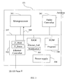
- Figure 3 depicts the electronic circuit of a wireless terminal adaptor 101 in accordance with the first aspect of the invention, using the DECT European standard, able to be connected to a 10 or 100 Mbit/s Ethernet terminal.
- the wireless terminal adaptor operates in the DECT mode as a portable part (that is to say mobile station).
- This wireless terminal adaptor can be integrated into an item of equipment of the computer, printer, digital copier etc type, or connected to one of the items of equipment cited above.
- the wireless terminal adaptor is connected to a terminal having an Ethernet interface.
- the electronic circuit 101 has, connected together by an address and data bus 307:
- an electrical power supply 306 is provided for supplying all the components of the electronic circuit 101 (the electrical links concerning the power supply are not shown).
- Link controller means here any means making it possible to determine whether there is an active terminal on the network, namely a terminal which is not switched off. Such a means is known to a person skilled in the art and will therefore not be described in detail here.
- the link controller 302 is a controller of the Ethernet type, which manages the Ethernet interface intended to communicate with a terminal of the wireless network 100, 103.
- the Ethernet controller 302 makes it possible to indicate to the microprocessor 303 any change in state of the Ethernet connection, as explained below in relation to Figures 7A and 7B.
- the Ethernet controller 302 contains two registers " IT_Status " and " IT_Mask " defined below.
- microprocessor is also adapted to implement the method of the invention and in particular the flow diagram illustrated in Figures 6A, 6B, 7A and 7B.
- the random access memory 305 contains registers which, for convenience, each bear the same name as the data which they contain, notably:
- the read only memory 304 contains registers which, for convenience, each bear the same name as the data which they contain, notably:
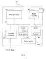
- Figure 4 depicts the electronic circuit of the wireless access point 102 according to the first aspect of the invention, using the DECT European standard, able to be connected to an Ethernet network having a transmission rate of 10 or 100 Mbit/s.
- the wireless access point operates in the DECT mode as a fixed part (that is to say base station).
- the electronic circuit 102 has, connected together by an address and data bus 407:
- an electrical power supply 406 is provided for supplying all the components of the electronic circuit 102 (the electrical links concerning the power supply are not shown).
- the link controller 402 is, in the particular embodiment described here, a controller of the Ethernet type, which manages the Ethernet interface intended to communicate with the cabled network 104.
- microprocessor is also adapted to implement the method of the invention and in particular the flow diagram illustrated in Figures 5A and 5B.
- the random access memory 405 contains registers which, for convenience, each bear the same name as the data which they contain, notably:
- the read only memory 404 contains registers which, for convenience, each bear the same name as the data which they contain, notably:
- the filter of the wireless access point 102 that is to say the register " Filter " , is initialised after powering up, so that the access point transmits over the radio medium only the frames intended for broadcast: these are the frames whose destination address 201 (see Figure 2) is equal to FF-FF-FF-FF-FF in hexadecimal.
- a radio connection In order to be able to exchange data between the access point and one or more wireless terminal adaptors, a radio connection must have previously been established between the terminal adaptor and the access point. It is the wireless terminal adaptor which initialises the radio connection with the access point.
- FIG. 5A depicts the processings executed by the microprocessor 403 of the access point 102 in accordance with the first aspect of the invention when, during a step 500, a radio connection is received by the access point 102 from one of the wireless terminal adaptors 101, this adaptor being designated here as ATi.
- the microprocessor 403 then performs an activation operation 501, which consists of setting to the value TRUE the element situated at the position corresponding to the adaptor ATi in the array " Read_Address " of the RAM 405. This element is denoted Read_Address[ATi] in Figure 5A. The effect of this operation is to activate the automatic address learning mode.
- Figure 5B depicts the processings executed by the microprocessor 403 of the access point 102 in accordance with the first aspect of the invention when, during a step 502, a data packet is received on a radio connection from the adaptor ATi.
- the microprocessor 403 then performs a test 503 on the value of the element in the array "Read_Address" situated at the position corresponding to the adaptor ATi.
- the microprocessor 403 then directly performs a transmission operation 505 described below.
- the operation of reading, updating and deactivation 504 consists of reading the source address 202 (see Figure 2) of the packet received (that is to say the MAC address of the communication terminal which sent the packet), and then updating the filter of the wireless access point 102 with this new address. If no address was previously associated with the adaptor ATi in the filter, this address is then initialised with the source address value of the packet currently being processed. If any address was already associated with the adaptor ATi, this address remains unchanged in the case where the address read in the received packet is identical to it. In the contrary case, this address is then replaced by the new address read in the packet currently being processed.
- microprocessor 403 deactivates the automatic address learning function, by setting to FALSE, in the random access memory 405, the element in the array "Read_Address" corresponding to the adaptor ATi.
- the processing phase corresponding to the automatic learning of the address of the terminal associated with the wireless adaptor ATi is then terminated.
- the Ethernet controller 402 is then responsible for transmitting this packet over the cabled network 104.
- Figure 6A depicts the processings carried out by the microprocessor 303 of the wireless terminal adaptor 101 according to the first aspect of the invention after powering up.
- Figure 6B depicts the processings carried out by the microprocessor 303 of the wireless terminal adaptor 101 according to the first aspect of the invention after the Ethernet controller 302 has signalled to the microprocessor 303 a change in state of the Ethernet link, this change in state being signalled by setting to the value TRUE the variable "Modification" contained in a register of the random access memory 305 (step 603).
- the microprocessor then performs a test 604, in order to know the value of the variable "Ethernet_Link".
- the result of test 604 is positive when the Ethernet link has changed from the inactive state to the active state. If test 604 is positive, a connection operation 605, which consists in establishing a connection with the access point 102, is then performed. If the result of test 604 is negative, a disconnection operation 606, which consists in breaking the connection established with the access point 102, is performed.
- the microprocessor 303 After either one of the connection 605 or disconnection 606 operations, the microprocessor 303 performs an updating step 607, which consists of resetting the variable " Modification " to FALSE, indicating that the taking into account of the change of state has been effected and making it possible to await a new notification of the change in the Ethernet link.
- Ethernet controller 302 of the wireless terminal adaptor 101 contains two registers:
- Figure 7A depicts the processings performed by the microprocessor 303 of the wireless terminal adaptor 101 according to the first aspect of the invention during the initialisation phase 600 illustrated in Figure 6A.
- the microprocessor 303 After either one of the updating operations 703 or 704, the microprocessor 303 performs an interrupt enable operation 705 which consists of positioning, in the register "IT_Mask", the field “Link” at the value logic "1” so as to enable the interrupt on the interrupt bus 308, so that the latter indicates any change in state of the Ethernet link.
- an interrupt enable operation 705 which consists of positioning, in the register "IT_Mask", the field “Link” at the value logic "1” so as to enable the interrupt on the interrupt bus 308, so that the latter indicates any change in state of the Ethernet link.
- Figure 7B shows the processings carried out by the microprocessor 303 of the terminal adaptor 101 in accordance with the first aspect of the invention when an interrupt is received from the Ethernet controller 302.
- a reading operation 707 is then performed, which consists of reading the register " IT_Status " .
- An updating operation 709 is then performed, which consists of setting the variable " Ethernet_Link “ to the value ACTIVE. If test 708 is negative, an updating operation 710 is then performed, which consists of setting the variable " Ethernet_Link " to the value INACTIVE.
- the microprocessor After either one of the updating operations 709 or 710, the microprocessor performs an operation 711 of change in state of the link, which consists of positioning the variable "Modification" to TRUE, then making it possible to start off the processings described above with the help of the flow diagram of Figure 6B.
- Figure 8 depicts an example of the flow of packets exchanged between the cabled network 104 and the terminal 103 connected to the wireless network 107, in accordance with the first aspect of the invention. The same description would apply to an exchange of packets between the cabled network 104 and the terminal 100, illustrated in Figure 1, also connected to the wireless network 107.
- the access point 102 After initialisation of the adaptor 101, the latter detects that the Ethernet link is active, and can therefore establish a connection 800 with the access point 102. After having received the connection from the adaptor 101, the access point 102 activates the automatic source address learning mode (activation operation 501 illustrated in Figure 5A).
- the filter of the access point is initialised in order to transmit only the packets of the general broadcast type.
- a packet 801 received from the cabled network, which is for example a packet from the terminal 105 intended for the terminal 106 also connected to the cabled network, is not transmitted to the wireless network 107.
- a packet 802 which is a packet of the general broadcast type (the general broadcast address being designated symbolically by the word "All" in Figure 8), is transmitted to the wireless adaptor 101, which then transmits it to the terminal 103.
- the packet 802 can be a packet of the ARP (" Address Resolution Protocol ") request type, containing the network address of the terminal 103.
- the terminal 103 must then reply to this message by a packet 803 of the ARP response type to the source of the packet 802, that is to say to the terminal 105 connected to the cabled network.
- the packet 803 is transmitted by the adaptor 101 to the access point 102.
- the access point 102 reads the source address of the packet 803 and initialises the filter with this address. Next it deactivates the automatic learning; thus the source address of the next packets received over this same connection will not be analysed (reading, updating and deactivation operation 504 illustrated in Figure 5B).
- the packet 803 is then transmitted by the access point 102 to the cabled network 104.
- the packet 805 is the response of the terminal 103 to the packet 804.
- the adaptor 101 is then disconnected from the access point 102 (disconnection 806). If a packet 807, whose destination address if that of the terminal 103, is received by the access point 102 coming from the terminal 105 of the cable network, this packet is not transmitted, since the connection with the terminal 103 is no longer active.
- the adaptor 101 then establishes a new connection 808 with the access point 102.
- the access point 102 then once again activates the automatic learning mode for the source address.
- the filter still contains the address of the terminal 103.
- the terminal 109 after it is powered up, the terminal 109, newly connected in place of the terminal 103, sends a general broadcast message 809, which is transmitted to the access point 102 by means of the adaptor 101.
- the access point 102 On reception of the packet 809, the access point 102 reads the source address (that of the terminal 109), which is different from that contained in the filter (which stored the address of the terminal 103). The old address (that of the terminal 103) is therefore replaced by the new address (that of the terminal 109).
- the filter is updated in real time. A terminal which has left the wireless local network 107 is thus rapidly erased from the filter.
- the learning mode is once again deactivated (operation 504 illustrated in Figure 5B) and the packet 809 is transmitted over the cable network 104.
- the terminal 105 of the cabled network and the terminal 109 can exchange packets, such as the packets 810 and 811, illustrated by way of in no way limitative example in Figure 8.
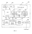
- Figure 9 depicts the electronic circuit 900 of a wireless access point 102 in accordance with the second aspect of the invention, which can be connected to an Ethernet network having a transmission rate of 10 or 100 Mbit/s, and a wireless terminal adaptor 101 in accordance with the second aspect of the invention, provided with an Ethernet interface.
- the wireless terminal adaptor 101 can be integrated into equipment of the computer, printer, digital copier etc type or connected to one of these items of equipment having an Ethernet interface.
- the wireless terminal adaptor 101 is an external device, distinct from the terminal 100 or 103, which makes it possible to develop the same architecture and to use the same electronic components as for the wireless access point.
- the electronic circuit 900 has, connected together by a control signal, address and data bus 913:
- the network controller 906 is an Ethernet controller, since an example is described where the cabled network 104 is of the Ethernet type. However, this example is in no case limitative and, in general terms, the two networks which communicate together by means of the access point can be of any type.
- the main processor 901 is adapted to implement the filtering method of the invention and in particular the flow diagrams described in Figures 10, 11 and 12.
- the processor manages a radio controller 905 which transmits and receives radio frames by means of an antenna 912.
- the read only memory 902 contains operating programs for the processor 901 (" Program3 " and " Program4 ”) , whilst the random access memory 903 temporarily stores the data processed, that is to say the data bits contained in the packets arriving at the circuit 900, either on the radio side, via the antenna 912, or on the Ethernet side, via the 10/100 Base T interface.
- the EEPROM memory 904 makes it possible to store configuration parameters, such as identifiers, such as for example the radio address peculiar to the terminal 100 or 103, and signalling or correction parameters, allowing for example to adjust operating parameters of the radio module.
- a two-position switch 910 connected to the processor 901 gives the operator the possibility of choosing, either the access point mode, or the terminal adaptor mode.
- the processor will execute the program called " Program3 " , otherwise it will execute the program called " Program4 " . Any change in position of the switch 910 generates an interrupt, which is processed by the processor 901.
- a serial interface 909 makes it possible to control the processor 901 by means of an external console and in particular to write in the memory 902 possible new versions of the programs " Program3 " and/or " Program4 " .
- the Ethernet controller 906 has its own MAC address and manages the Ethernet interface by means of a transceiver 907, which can be integrated into the controller 906.
- a transformer 908 effects the adaptation with an Ethernet interface, which is a 10/100 Base T interface in a preferred embodiment.
- an electrical power supply 911 is provided for supplying all the components of the electronic circuit 900 (the electrical links concerning the power supply are not shown).
- the program executed by the processor 901 is capable of managing a radio protocol, for example the one described in the DECT standard, specified by the ETSI (EN 300 175, 1991). Consequently the radio controller 905 and its antenna 912 are compatible with the radio standard used.
- the flow diagram of Figure 10 describes the procedure which unfolds when the electronic circuit 900 is powered up, during a step 1001, in accordance with the second aspect of the invention.
- an Ethernet controller can be used in at least one of the following two modes:
- Ethernet controller 906 On powering up, the Ethernet controller 906 is first used in a mode without filtering.
- the processor 901 determines the position of the switch 910 by testing for example whether the switch is in a position "1", designating arbitrarily the access point operating mode. If such is the case, the circuit 900 will execute "Program3" (step 1004) for an access point; if not, it will execute "Program4" (step 1006) for a terminal adaptor.
- the programs "Program3" and "Program4" will have to be capable of responding at any time to a change in position of the switch (test 1005 or 1007). In the case of a positive response to test 1005 or 1007, the start-up step 1002 described above is returned to.
- the processor activates the filtering mode for the Ethernet controller (step 1008).
- FIG. 11 describes the functioning of the access point 102 in accordance with the second aspect of the invention, in the case where, during test 1003 illustrated in Figure 10, the processor 901 is controlled by the switch 910 in order to execute "Program3" (task 1101).
- the processor 901 recovers the source address of the received packet, which corresponds to the MAC address of the terminal 100 or 103. Next it allocates this address to the Ethernet controller 906, by programming of the controller registers, and transmits the received packet to it. The Ethernet controller then sends this packet over the 10/100 Base T interface. These operations are grouped together in step 1103.
- the Ethernet controller 906 In the case of reception of an Ethernet packet over the 10/100 Base T interface, detected during a test 1104, the Ethernet controller 906 automatically performs a test 1105 on the nature of the packet. If the packet received is a general broadcast packet, it is transmitted to the processor 901, which is responsible for retransmitting it over the radio, during a step 1107. For the other packets, the Ethernet controller 906 makes a comparison of the destination address of the received packet with its own MAC address (test 1106), which corresponds to the MAC address of the terminal 100 or 103. In the case of a negative result, that is to say if the destination address is different from the MAC address of the Ethernet controller, the packet is rejected, given that it is not intended for the terminal 100 or 103; otherwise, it is transmitted over the radio during step 1107.
- the program performs a continual loop; however, this may be interrupted by an intervention by the operator, who can actuate the switch 910, as described above with the help of Figure 10.
- the flow diagram in Figure 12 describes the functioning of the terminal adaptor 101 in accordance with the second aspect of the invention, in the case where, during test 1003 illustrated in Figure 10, the processor 901 is controlled by the switch 910 in order to execute "Program4" (task 1201).
- the processor 901 transmits the packet to the Ethernet controller 906, which is responsible for sending it over the 10/100 Base T interface. These instructions are grouped together in step 1203.
- the Ethernet controller 906 transmits the packet to the processor 901, which is responsible for retransmitting it over the radio (step 1205).
- the program effects a continual loop; however, this can be interrupted by an intervention from the operator, who can actuate the switch 910, as described above with the help of Figure 10.
Landscapes
- Engineering & Computer Science (AREA)
- Computer Networks & Wireless Communication (AREA)
- Signal Processing (AREA)
- Mobile Radio Communication Systems (AREA)
- Small-Scale Networks (AREA)
- Computer And Data Communications (AREA)
Abstract
Description
- The present invention relates to methods and devices for transmitting data packets in a telecommunications network, and to systems, information storage means and computer programs corresponding to them.
- Especially, the invention is effectively adopted in the field of the interconnection of wireless networks with cabled networks.
- More precisely, according to a first aspect, the invention is described in its application to the learning of the MAC ("Medium Access Control") address for a wireless point of access and a wireless terminal adaptor.
- The European standard EN 301 649, 1999, DECT ("Digital Enhanced Cordless Telecommunications") describes the use of DECT radio technology for interconnection with equipment or networks of the Ethernet type (IEEE 802.3).
- Document ANSI/IEEE Std 802.1 D, 1998 Edition, "Part 3: Media Access Control (MAC) Bridges", also designated as ISO/IEC 15802-3:1998, describes a general method for the operation of MAC Bridges, for the purpose of compatible interconnection of data processing equipment using the IEEE 802 MAC Service supported by interconnected IEEE 802 Local Area Networks using different or identical Media Access Control methods.
- Through the document
US-A-5 339 316 a local wireless network system is known which comprises: - a local cabled network, and
- at least one local wireless network cooperating with the cabled network through an access point which has a gateway function.
- When a source station, situated in the wireless network, transmits a data packet to the cabled network, the access point saves the source address of the packet. This saving of the source address is done for each packet received from a wireless terminal through the access point.
- It may be useful to ensure the learning of the source address on each packet in this case where there is great mobility in the wireless network:
- new terminals joining the wireless network,
- terminals moving from one cell in the wireless network to another,
- etc.
- However, in a system where the equipment items in the wireless network are not very mobile, as is the case for example with digital copiers, the frequency at which the equipment items are likely to be changed is very small. Therefore, in this situation, reading the source address on each packet constitutes a drawback.
- There are also known, through the document
US-A-5 812 531 , a method and apparatus for interconnecting a wireless network with a cabled network. In order to be able to obtain the address of all the wireless nodes, the method uses a topology determination message which is regularly broadcast in the wireless network to all the terminals. - This method has the drawback of consuming a substantially large radio bandwidth and is in particular adapted to an environment where the wireless equipment items are very mobile.
- According to a second aspect, the invention concerns the filtering of data packets from a first telecommunications network to a second telecommunications network. As seen above, the apparatus effecting the bridge between the two networks and fulfilling the filtering function is referred to as the access point. The data packets include the network address of the transmitting device, referred to as the source address, and the network address of the receiving device, referred to as the destination address.
- The invention applies to the situation where a single terminal, having an address compatible with the first network, is accessible from the first network by means of the second network. For example, a first terminal of a cabled network may be accessible through a second terminal of the cable network only by passing through a wireless telecommunications network, to which the first terminal is connected by means of a wireless terminal adaptor.
- In the field of the interconnection of local networks, it is well known to use a bridge between two networks. The bridge generally functions by means of a specific memory, which contains the table of addresses of the first network.
- For each packet coming from this network, the bridge generally compares the destination address with the addresses contained in the table. If the destination address corresponds to an address contained in the table, this means that the packet is intended for a terminal of the first network and the packet is not transmitted to the second network. In the contrary case, this means that the packet may be intended for a terminal in the second network; it is therefore transmitted to this second network.
- It is known from document
EP-A-0 695 059 to use an access point as an internetworking device that relays data packets based on address which are registered with the access point. - Improvements to this filtering system are known. For example, the document
US-A-5 959 976 makes it possible to reduce the memory capacity of the table of addresses, keeping only a flag equal to 0 or 1 in place of the complete address. Moreover, the documentUS-A-5 396 493 proposes to relieve the main processor of the comparison of the addresses, allocating this task to the network controller, again by means of a table. - Nevertheless, in spite of these improvements, the use of such a table of addresses notably has the drawbacks of requiring the presence of an additional memory and the use of a complex controller provided with specific functions for filtering several addresses.
- In addition, through the document
EP-A-0 785 658 the allocation of an address for filtering is known. In this document, the access point is a bridge between a local network and a wireless network composed of terminal adaptors. The radio address of the terminal is allocated to the address of the adaptor to which it is connected. Thus the adaptor can filter, at a wireless link, the packets intended for the terminal. However, such a system has the drawback of representing a load for the wireless network. - The purpose of the present invention is to remedy the above drawbacks.
- To remedy such drawbacks, this invention proposes a method of filtering data packets according to
claim 1 and an access point according to claim 3. Other features are recited in the subclaims. - The invention has many advantages, notably:
- it affords a reduction in the processing time spent for the automatic learning of the address;
- it allows real-time updating of the information for filtering the data packets coming from the cabled network before transmission over the radio medium (this advantage is explained below);
- it constitutes a solution which can be achieved without any additional electronic component, by software means, whence a low cost;
- it is a solution independent of the filtering method chosen (by software or dedicated electronic component);
- it is a solution specially adapted to make it possible to provide positioning mobility to heavy and not very mobile equipment items, such as digital copiers, that is to say it confers great flexibility for changing the position of these equipment items if necessary.
- Thus, the invention optimises the processing time for a packet received over the radio port of a wireless access point for learning the source address, in order to effect a filtering function.
- In addition, the invention makes it possible, in a wireless network, to filter the data coming from a cabled network with a higher transmission rate and is adapted to a system where the access point on the cabled network is intended to communicate with wireless terminal adaptors, to which only one item of network termination equipment can be connected, for example a printer, a computer or a digital copier.
- The present invention makes it possible to reduce the processing time for each packet, by reading the source address of an item of equipment connected to the wireless network, not for each packet, but only when this is necessary, that is to say when an item of equipment in the wireless network is likely to have been changed. This allows to improve the performance of the whole of the system.
- This invention makes it possible to dispense with the use of electronic components or additional memories for the filtering function, and therefore to reduce the development and manufacturing costs. This is because, on the one hand, the invention uses no additional memory, since the address to be filtered is allocated to the address proper of the network controller of the access point and, on the other hand, the invention does not require the use of a complex controller provided with functions for the filtering of several addresses.
- Moreover, according to the present invention, the access point with the address of the terminal is "transparent" seen from the first network. The invention makes it possible to completely effect the filtering at the access point, which reduces the load on the wireless network.
- The terminal whose network address it is sought to filter is for example a printer or computer or digital copier connected to a local network by means of a specific link such as a radio or infrared connection.
- The invention also has other advantages, notabiy:
- it affords a reduction in the processing time for each packet without the development of specific software;
- it is a solution which does not use the resources of the main processor, given that the network controller is responsible for the operation;
- it allows a reduction in the load on the network providing the link with the terminal and the access point;
- in the case where the terminal is connected to a terminal adaptor, the electronic cards are identical for the access point and the adaptor.
- The invention also relates to a computer readable medium according to claim 4, microprocessor storing instructions of a computer program, making it possible and wich may be partially or totally removable.
- The invention also relates to a computer program according to claim 6.
- The particular characteristics not expressly mentioned above and the advantages of the computer readable medium and of the computer program being the same as those of the method according to the invention, they are not repeated here.
- Other particular characteristics and advantages of the invention will emerge from a reading of the following detailed description of particular embodiments, given by way of in no way limitative examples. The description refers to the drawings which accompany it, in which:
- Figure 1 depicts schematically a local wireless telecommunications network, able to be connected to a local cabled telecommunications network by means of a wireless access point;
- Figure 2 depicts schematically the structure of an Ethernet MAC data frame;
- Figure 3 depicts schematically the structure of a wireless terminal adaptor in accordance with the first aspect of the invention, in a particular embodiment;
- Figure 4 depicts schematically the structure of a wireless access point according to the invention, in a particular embodiment;
- Figures 5A and 5B are flow diagrams illustrating the functioning of a wireless access point according to the invention, in a particular embodiment;
- Figures 6A, 6B, 7A and 7B are flow diagrams illustrating the functioning of a wireless terminal adaptor according to the invention, in a particular embodiment;
- Figure 8 depicts schematically the information flows exchanged by a communication terminal, the wireless terminal adaptor which is associated with it, a wireless access point and a cabled network, such as the ones illustrated in Figure 1, when the method of the invention is implemented, in a particular embodiment;
- Figure 9 depicts schematically the structure of a wireless access point and a wireless terminal adaptor according to the second aspect of the invention, in the form of an electronic circuit, in a particular embodiment;
- Figure 10 is a flow diagram illustrating the functioning of the electronic circuit of Figure 9 on powering up, in a particular embodiment;
- Figure 11 is a flow diagram illustrating the functioning of a wireless access point according to the second aspect of the invention, in a particular embodiment; and
- Figure 12 is a flow diagram illustrating the functioning of a wireless terminal adaptor according to the second aspect of the invention, in a particular embodiment.
- Figure 1 depicts a wireless
local network 107 which can be interconnected to a cabledlocal network 104 by means of awireless access point 102. - The wireless
local network 107 consists of several items ofterminal equipment - In a preferred embodiment of the invention, the
terminals - Each terminal is connected to the wireless local network by means of a
wireless terminal adaptor 101, possibly integrated into the terminal. - A terminal adaptor makes it possible to connect one and only one terminal.
- According to a preferred embodiment of the invention, the wireless terminal adaptor is connected to the terminal by an interface of the 10 or 100 base T (Ethernet) type.
- The number of adaptors of the wireless local network terminal is limited by the capacity of the wireless access point.
- According to a preferred embodiment of the invention, the number of
terminal adaptors 101 supported by theaccess point 102 is limited to one. - According to a preferred embodiment of the invention, the wireless communication between the
access point 102 and thewireless terminal adaptors 101 uses the DECT digital radio communication technology specified by the ETSI, EN 300 175, 1991. - According to a preferred embodiment of the invention, the cabled
local network 104 is a network of the Ethernet type having a transmission rate of 10 and/or 100 Mbit/s. - The items of
equipment network 104. For example, the terminal 105 is a print server and theterminals - The DECT radio technology makes it possible to achieve a maximum transmission rate of 552 kbit/s whilst the transmission rate of the cabled network can attain 100 Mbit/s. The
wireless access point 102 cannot therefore transfer over the radio medium all the data circulating on the cabled network without risk of unnecessarily loading the radio link or even losing data. It is necessary to filter the data packets coming from the cabled network before transmitting them over the wireless network. Only the packets intended for thewireless network terminals - The packets are filtered at level 2 of the OSI ("Open Systems Interconnection") model layer, that is to say at the level of the MAC ("Medium Access Control") layer of the Ethernet network.
- Figure 2 depicts the structure of an Ethernet MAC data frame designated by the
reference 200 in the drawing (defined by IEEE 802.3). - This frame is composed of several fields. For the present invention, the first two
fields - The field "L" contains the length of the data contained in the frame, in 2 bytes. The field "Info" contains the data proper, in a number of bytes which can vary from 0 to 1500. The field "Pad" contains binary padding elements, in 46 bytes at a maximum, so that the total number of bytes contained in the fields "DA", "SA", "L", "Pad" and "FCS" is equal to 64. The field "FCS" ("Frame Check Sequence") contains a check sequence allowing to detect transmission errors.
- When the access point receives, from the cabled
network 104, a data packet whosedestination address 201 corresponds to the MAC address of one of thecommunication terminals wireless network 107, this packet must then be transmitted over the radio medium. On the other hand, when the access point receives a packet whosedestination address 201 does not correspond to the MAC address of one of theterminals destination address 201 corresponds to a "broadcast" address. For this purpose, the access point effects a filtering of the data which reach it. - In order to be able to fulfil this filtering function, the access point must know the MAC addresses of the terminals connected to the wireless local network. The invention proposes an automatic learning method (that is to say without the intervention of an operator) for the MAC address, which makes it possible to form a filtering table at the wireless access point. The invention is independent of the chosen filtering method (whether the filtering function is carried out totally by software means implemented by a microprocessor, or the filtering function is performed by a specific adapted component of the CAM ("Content Addressable Memory") type.
- On the other hand, given that the access point supports only one MAC address per wireless terminal adaptor (which is equivalent to a single MAC address per radio connection, since there is one radio connection with the access point per adaptor), which is the address to be taken into account during the learning (it will be seen later that the access point reads the source address on the first data packet received), the invention applies only when the wireless terminal adaptor does not have its own MAC address, failing which the access point would not "see" the MAC address of the communication terminals. This absence of MAC address peculiar to the wireless adaptor has several advantages: it simplifies the design, reduces the cost of implementation and affords a saving in processing time.
- In accordance with the invention, at the time of the reception, over the radio link, of a packet coming from one of the
terminals access point 102 recovers the source address which corresponds to the MAC address of the terminal. This address becomes the MAC address of theaccess point 102. - With regard to the
wireless terminal adaptor 101, no filtering function is necessary. All the packets received over the radio are retransmitted over the 10/100 Base T interface, and all the packets received over the 10/100 Base T interface are retransmitted over the radio. - On the other hand, given that, for the
access point 102, two items of network equipment (the terminal 100 or 103 and the access point 102) have the same MAC address, theaccess point 102 cannot be administered at a distance. The same applies for thewireless terminal adaptor 101, which is transparent vis-à-vis the cablednetwork 104. - In a variant, if the terminal 100 or 103 does not have its own address, it is the address of the
wireless terminal adaptor 101 which becomes the original address of the packets coming from the terminal 100 or 103. - Figure 3 depicts the electronic circuit of a
wireless terminal adaptor 101 in accordance with the first aspect of the invention, using the DECT European standard, able to be connected to a 10 or 100 Mbit/s Ethernet terminal. - The wireless terminal adaptor operates in the DECT mode as a portable part (that is to say mobile station). This wireless terminal adaptor can be integrated into an item of equipment of the computer, printer, digital copier etc type, or connected to one of the items of equipment cited above.
- According to a preferred embodiment of the invention, the wireless terminal adaptor is connected to a terminal having an Ethernet interface.
- The
electronic circuit 101 has, connected together by an address and data bus 307: - a
radio unit 301, provided with an antenna, - a
link controller 302, - a
microprocessor 303, - a read only
memory ROM 304, and - a random
access memory RAM 305. - In addition, an
electrical power supply 306 is provided for supplying all the components of the electronic circuit 101 (the electrical links concerning the power supply are not shown). - "Link controller" means here any means making it possible to determine whether there is an active terminal on the network, namely a terminal which is not switched off. Such a means is known to a person skilled in the art and will therefore not be described in detail here.
- In the particular embodiment described here, the
link controller 302 is a controller of the Ethernet type, which manages the Ethernet interface intended to communicate with a terminal of thewireless network bus 308, theEthernet controller 302 makes it possible to indicate to themicroprocessor 303 any change in state of the Ethernet connection, as explained below in relation to Figures 7A and 7B. TheEthernet controller 302 contains two registers "IT_Status" and "IT_Mask" defined below. - All the components illustrated in Figure 3 are well known to a person skilled in the art of communication circuits with processor and, more generally, information processing circuits. They are therefore not detailed here. The
electronic circuit 101 and, in particular, themicroprocessor 303 is adapted to exploit all the capabilities of the DECT standard known at the time of the present invention. - The microprocessor is also adapted to implement the method of the invention and in particular the flow diagram illustrated in Figures 6A, 6B, 7A and 7B.
- The
random access memory 305 contains registers which, for convenience, each bear the same name as the data which they contain, notably: - a register "Ethernet_Link", in which there is stored the state of the Ethernet link, which can take the value ACTIVE or INACTIVE, depending on whether or not there is an active communication terminal (that is to say one which is powered up) connected to the
terminal adaptor 101, and - a register "Modification", which indicates, when its state is TRUE, that a modification of the Ethernet link has been signalled by an interrupt on the interrupt
bus 308. - The read only
memory 304 contains registers which, for convenience, each bear the same name as the data which they contain, notably: - a register "
Program 1", in which there is stored the operating program of themicroprocessor 303. - Figure 4 depicts the electronic circuit of the
wireless access point 102 according to the first aspect of the invention, using the DECT European standard, able to be connected to an Ethernet network having a transmission rate of 10 or 100 Mbit/s. - The wireless access point operates in the DECT mode as a fixed part (that is to say base station).
- The
electronic circuit 102 has, connected together by an address and data bus 407: - a
radio unit 401, provided with an antenna, - a
link controller 402, - a
microprocessor 403, - a read only
memory ROM 404, and - a random
access memory RAM 405. - In addition, an
electrical power supply 406 is provided for supplying all the components of the electronic circuit 102 (the electrical links concerning the power supply are not shown). - The
link controller 402 is, in the particular embodiment described here, a controller of the Ethernet type, which manages the Ethernet interface intended to communicate with the cablednetwork 104. - All the components illustrated in Figure 4 are well known to a person skilled in the art of communication circuits with processor, and, more generally, information processing circuits. They are therefore not detailed here. The
electronic circuit 102 and in particular themicroprocessor 403 is adapted to exploit all the capabilities of the DECT standard known at the time of the present invention. - The microprocessor is also adapted to implement the method of the invention and in particular the flow diagram illustrated in Figures 5A and 5B.
- The
random access memory 405 contains registers which, for convenience, each bear the same name as the data which they contain, notably: - a register "Filter", containing an array with as many elements as there are wireless terminal adaptors connected to the
wireless network 107; this array establishes a match between MAC addresses and radio addresses (that is to say identifying a given radio connection); and - a register "Read_Address", containing an array with as many Booleans as there are wireless terminal adaptors connected to the
wireless network 107; the Booleans in this register have the value TRUE if the activation of the learning of the address is necessary for the corresponding wireless terminal adaptor, or the value FALSE otherwise. - The read only
memory 404 contains registers which, for convenience, each bear the same name as the data which they contain, notably: - a register "Program2", in which there is stored the operating program of the
microprocessor 403. - The filter of the
wireless access point 102, that is to say the register "Filter", is initialised after powering up, so that the access point transmits over the radio medium only the frames intended for broadcast: these are the frames whose destination address 201 (see Figure 2) is equal to FF-FF-FF-FF-FF-FF in hexadecimal. - In order to be able to exchange data between the access point and one or more wireless terminal adaptors, a radio connection must have previously been established between the terminal adaptor and the access point. It is the wireless terminal adaptor which initialises the radio connection with the access point.
- Thus, after initialisation of the filtering function of the
wireless access point 102, no frame from the cablednetwork 104 is transmitted over the radio medium as long as no radio connection is established by awireless terminal adaptor 101 with thewireless access point 102. - Figure 5A depicts the processings executed by the
microprocessor 403 of theaccess point 102 in accordance with the first aspect of the invention when, during astep 500, a radio connection is received by theaccess point 102 from one of thewireless terminal adaptors 101, this adaptor being designated here as ATi. - The
microprocessor 403 then performs anactivation operation 501, which consists of setting to the value TRUE the element situated at the position corresponding to the adaptor ATi in the array "Read_Address" of theRAM 405. This element is denoted Read_Address[ATi] in Figure 5A. The effect of this operation is to activate the automatic address learning mode. - Figure 5B depicts the processings executed by the
microprocessor 403 of theaccess point 102 in accordance with the first aspect of the invention when, during astep 502, a data packet is received on a radio connection from the adaptor ATi. - The
microprocessor 403 then performs atest 503 on the value of the element in the array "Read_Address" situated at the position corresponding to the adaptor ATi. - If this element is equal to TRUE, then an operation of reading, updating and
deactivation 504 described below is performed. - If this element is equal to FALSE, the
microprocessor 403 then directly performs atransmission operation 505 described below. - If the element is equal to TRUE, the operation of reading, updating and
deactivation 504 consists of reading the source address 202 (see Figure 2) of the packet received (that is to say the MAC address of the communication terminal which sent the packet), and then updating the filter of thewireless access point 102 with this new address. If no address was previously associated with the adaptor ATi in the filter, this address is then initialised with the source address value of the packet currently being processed. If any address was already associated with the adaptor ATi, this address remains unchanged in the case where the address read in the received packet is identical to it. In the contrary case, this address is then replaced by the new address read in the packet currently being processed. - Next the
microprocessor 403 deactivates the automatic address learning function, by setting to FALSE, in therandom access memory 405, the element in the array "Read_Address" corresponding to the adaptor ATi. - The processing phase corresponding to the automatic learning of the address of the terminal associated with the wireless adaptor ATi is then terminated.
- The
transmission operation 505, which consists of transmitting the packet to theEthernet controller 402, is then executed. TheEthernet controller 402 is then responsible for transmitting this packet over the cablednetwork 104. - The processings which have just been described in relation to Figures 5A and 5B make it possible:
- to activate the terminal address learning mode each time a new radio connection is established between the access point and a terminal, by means of a wireless adaptor of the latter, and
- to deactivate the address learning mode as soon as the terminal address has been read from the source address of the first packet received over a given connection.
- Thus the reading of the source address is effected only on the first packet received over a given radio connection, which reduces the processing time for the following packets.
- Figure 6A depicts the processings carried out by the
microprocessor 303 of thewireless terminal adaptor 101 according to the first aspect of the invention after powering up. - After an
initialisation phase 600, described below in relation to Figure 7A, themicroprocessor 303 checks the state of the activity of the Ethernet link during atest 601, by testing the value of the variable "Ethernet_Link" contained in therandom access memory 305. Iftest 601 is positive ("Ethernet_Link" = ACTIVE), this means that there is indeed an active communication terminal (that is to say one which is powered up) connected to the terminal adaptor. Aconnection operation 602 is then performed, which consists of establishing a radio connection between theadaptor 101 and theaccess point 102. If thetest 601 is negative, nothing happens as long as the Ethernet link does not become active. - Figure 6B depicts the processings carried out by the
microprocessor 303 of thewireless terminal adaptor 101 according to the first aspect of the invention after theEthernet controller 302 has signalled to the microprocessor 303 a change in state of the Ethernet link, this change in state being signalled by setting to the value TRUE the variable "Modification" contained in a register of the random access memory 305 (step 603). - The microprocessor then performs a
test 604, in order to know the value of the variable "Ethernet_Link". The result oftest 604 is positive when the Ethernet link has changed from the inactive state to the active state. Iftest 604 is positive, aconnection operation 605, which consists in establishing a connection with theaccess point 102, is then performed. If the result oftest 604 is negative, adisconnection operation 606, which consists in breaking the connection established with theaccess point 102, is performed. - After either one of the
connection 605 ordisconnection 606 operations, themicroprocessor 303 performs an updatingstep 607, which consists of resetting the variable "Modification" to FALSE, indicating that the taking into account of the change of state has been effected and making it possible to await a new notification of the change in the Ethernet link. - The processings which have just been described in relation to Figures 6A and 6B make it possible:
- to detect in real time the presence or absence of an active terminal (one which is powered up) connected to a
terminal adaptor 101, and - to establish a radio connection with the access point only when there is an active terminal connected to the
terminal adaptor 101. - The combination of the processings illustrated by Figures 5A, 5B, 6A and 6B makes it possible to activate the automatic learning of the address of a terminal each time a new radio connection is established, that is to say each time the equipment item connected to the wireless terminal adaptor is likely to have been changed:
- either after the powering up of the terminal adaptor,
- or after the disconnection and then reconnection of the Ethernet cable between the terminal 100 or 103 and the
wireless terminal adaptor 101. - As described in relation to Figure 3, the
Ethernet controller 302 of thewireless terminal adaptor 101 contains two registers: - "IT_Status": This register contains different information fields enabling to identify the state of the Ethernet controller. Notably, a field "Link" makes it possible to identify the state of the link: if this field contains a logic "1", this means that the link is active, otherwise, that the link is inactive. Other fields of the register "IT_Status" can make it possible to identify the reception of an Ethernet packet, the end of transmission of a packet and other information necessary to the control of the Ethernet controller by the
microprocessor 303; - "IT_Mask": This register contains different information fields making it possible to validate or not the interrupt on the interrupt
bus 308 for different types of event. Notably, a field "Link" makes it possible to enable the generation of an interrupt during a change in state of the link. Other links can make it possible to enable the generation of an interrupt during the reception of an Ethernet packet or the end of transmission of a packet by the Ethernet controller. In general terms, if a field in the register "IT_Mask" contains a logic "1", this means that an interrupt is enabled. - Figure 7A depicts the processings performed by the
microprocessor 303 of thewireless terminal adaptor 101 according to the first aspect of the invention during theinitialisation phase 600 illustrated in Figure 6A. - The microprocessor checks the state of the activity of the Ethernet link by performing first of all a reading of the register "IT_Status" (reading operation 701). Then, during a
test 702, themicroprocessor 303 tests the value of the field "Link' in this register. Iftest 702 is positive (Field "Link" = 1), this means that there is indeed an active terminal connected to the terminal adaptor. An updatingoperation 703 is then performed, which consists of setting the variable "Ethernet_Link" to the value ACTIVE. Iftest 702 is negative, an updatingoperation 704 is then performed, which consists of setting the variable "Ethernet_Link" to the value INACTIVE. - After either one of the updating
operations microprocessor 303 performs an interrupt enableoperation 705 which consists of positioning, in the register "IT_Mask", the field "Link" at the value logic "1" so as to enable the interrupt on the interruptbus 308, so that the latter indicates any change in state of the Ethernet link. - Figure 7B shows the processings carried out by the
microprocessor 303 of theterminal adaptor 101 in accordance with the first aspect of the invention when an interrupt is received from theEthernet controller 302. - During a
step 706, such an interrupt is signalled by the interruptbus 308. Areading operation 707 is then performed, which consists of reading the register "IT_Status". Then, during atest 708, themicroprocessor 303 tests the value of the field "Link" of this register. If thetest 708 is positive (Field "Link" = 1), this means that there is indeed an active terminal connected to the terminal adaptor. An updatingoperation 709 is then performed, which consists of setting the variable "Ethernet_Link" to the value ACTIVE. Iftest 708 is negative, an updatingoperation 710 is then performed, which consists of setting the variable "Ethernet_Link" to the value INACTIVE. - After either one of the updating
operations operation 711 of change in state of the link, which consists of positioning the variable "Modification" to TRUE, then making it possible to start off the processings described above with the help of the flow diagram of Figure 6B. - Figure 8 depicts an example of the flow of packets exchanged between the cabled
network 104 and the terminal 103 connected to thewireless network 107, in accordance with the first aspect of the invention. The same description would apply to an exchange of packets between the cablednetwork 104 and the terminal 100, illustrated in Figure 1, also connected to thewireless network 107. - After initialisation of the
adaptor 101, the latter detects that the Ethernet link is active, and can therefore establish aconnection 800 with theaccess point 102. After having received the connection from theadaptor 101, theaccess point 102 activates the automatic source address learning mode (activation operation 501 illustrated in Figure 5A). - After powering up, the filter of the access point is initialised in order to transmit only the packets of the general broadcast type. By way of non-limitative example, a
packet 801, received from the cabled network, which is for example a packet from the terminal 105 intended for the terminal 106 also connected to the cabled network, is not transmitted to thewireless network 107. On the other hand, apacket 802, which is a packet of the general broadcast type (the general broadcast address being designated symbolically by the word "All" in Figure 8), is transmitted to thewireless adaptor 101, which then transmits it to the terminal 103. - For example, the
packet 802 can be a packet of the ARP ("Address Resolution Protocol") request type, containing the network address of the terminal 103. The terminal 103 must then reply to this message by apacket 803 of the ARP response type to the source of thepacket 802, that is to say to the terminal 105 connected to the cabled network. Thepacket 803 is transmitted by theadaptor 101 to theaccess point 102. As the automatic source address learning mode is activated, theaccess point 102 reads the source address of thepacket 803 and initialises the filter with this address. Next it deactivates the automatic learning; thus the source address of the next packets received over this same connection will not be analysed (reading, updating anddeactivation operation 504 illustrated in Figure 5B). Thepacket 803 is then transmitted by theaccess point 102 to the cablednetwork 104. - Next a
packet 804, coming from theterminal 105 of the cabled network, intended for the terminal 103, can be transmitted over the radio medium, since the filter of theaccess point 102 has been programmed with the address of the terminal 103. Thepacket 805 is the response of the terminal 103 to thepacket 804. - If after the sending of the
packet 805 the user disconnects the Ethernet cable between thewireless adaptor 101 and the terminal 103, theadaptor 101 is then disconnected from the access point 102 (disconnection 806). If apacket 807, whose destination address if that of the terminal 103, is received by theaccess point 102 coming from theterminal 105 of the cable network, this packet is not transmitted, since the connection with the terminal 103 is no longer active. - If the user next reconnects a
new terminal 109 in place of the terminal 103, theadaptor 101 then establishes anew connection 808 with theaccess point 102. Theaccess point 102 then once again activates the automatic learning mode for the source address. At this moment, the filter still contains the address of the terminal 103. Thus, if thesame terminal 103 is subsequently reconnected to theadaptor 101, the system can refunction immediately, without a new learning being necessary. - In the non-limitative example given here, after it is powered up, the terminal 109, newly connected in place of the terminal 103, sends a
general broadcast message 809, which is transmitted to theaccess point 102 by means of theadaptor 101. On reception of thepacket 809, theaccess point 102 reads the source address (that of the terminal 109), which is different from that contained in the filter (which stored the address of the terminal 103). The old address (that of the terminal 103) is therefore replaced by the new address (that of the terminal 109). Thus the filter is updated in real time. A terminal which has left the wirelesslocal network 107 is thus rapidly erased from the filter. After reading of the address of the terminal 109, the learning mode is once again deactivated (operation 504 illustrated in Figure 5B) and thepacket 809 is transmitted over thecable network 104. Next theterminal 105 of the cabled network and the terminal 109 can exchange packets, such as thepackets - Figure 9 depicts the
electronic circuit 900 of awireless access point 102 in accordance with the second aspect of the invention, which can be connected to an Ethernet network having a transmission rate of 10 or 100 Mbit/s, and awireless terminal adaptor 101 in accordance with the second aspect of the invention, provided with an Ethernet interface. - The
wireless terminal adaptor 101 can be integrated into equipment of the computer, printer, digital copier etc type or connected to one of these items of equipment having an Ethernet interface. In a preferred embodiment of the invention, thewireless terminal adaptor 101 is an external device, distinct from the terminal 100 or 103, which makes it possible to develop the same architecture and to use the same electronic components as for the wireless access point. - The
electronic circuit 900 has, connected together by a control signal, address and data bus 913: - a microprocessor or
main processor 901, - a
network controller 906, - a read only
memory ROM 902, - a random
access memory RAM 903, - an electrically erasable and
programmable memory EEPROM 904. - In the particular embodiment described here, the
network controller 906 is an Ethernet controller, since an example is described where the cablednetwork 104 is of the Ethernet type. However, this example is in no case limitative and, in general terms, the two networks which communicate together by means of the access point can be of any type. - The
main processor 901 is adapted to implement the filtering method of the invention and in particular the flow diagrams described in Figures 10, 11 and 12. By means of aninterface bus 914, the processor manages aradio controller 905 which transmits and receives radio frames by means of anantenna 912. - The read only
memory 902 contains operating programs for the processor 901 ("Program3" and "Program4"), whilst therandom access memory 903 temporarily stores the data processed, that is to say the data bits contained in the packets arriving at thecircuit 900, either on the radio side, via theantenna 912, or on the Ethernet side, via the 10/100 Base T interface. - The
EEPROM memory 904 makes it possible to store configuration parameters, such as identifiers, such as for example the radio address peculiar to the terminal 100 or 103, and signalling or correction parameters, allowing for example to adjust operating parameters of the radio module. - A two-
position switch 910 connected to theprocessor 901 gives the operator the possibility of choosing, either the access point mode, or the terminal adaptor mode. In the first case, the processor will execute the program called "Program3", otherwise it will execute the program called "Program4". Any change in position of theswitch 910 generates an interrupt, which is processed by theprocessor 901. - A
serial interface 909 makes it possible to control theprocessor 901 by means of an external console and in particular to write in thememory 902 possible new versions of the programs "Program3" and/or "Program4". - The
Ethernet controller 906 has its own MAC address and manages the Ethernet interface by means of atransceiver 907, which can be integrated into thecontroller 906. Atransformer 908 effects the adaptation with an Ethernet interface, which is a 10/100 Base T interface in a preferred embodiment. - In addition, an
electrical power supply 911 is provided for supplying all the components of the electronic circuit 900 (the electrical links concerning the power supply are not shown). - All the components illustrated in Figure 9 are well known to a person skilled in the art of communication circuits with processors, and, more generally, information processing circuits. They are therefore not detailed any further here.
- In order to be able to exchange data between the
access point 102 and theterminal adaptor 101, the program executed by theprocessor 901 is capable of managing a radio protocol, for example the one described in the DECT standard, specified by the ETSI (EN 300 175, 1991). Consequently theradio controller 905 and itsantenna 912 are compatible with the radio standard used. - The flow diagram of Figure 10 describes the procedure which unfolds when the
electronic circuit 900 is powered up, during astep 1001, in accordance with the second aspect of the invention. - During a start-up
step 1002, theprocessor 901 initialises the MAC address of theEthernet controller 906 to the value 0 and its filtering function, in the deactivated state, which results in a writing operation in the internal registers of the controller. As a general rule, an Ethernet controller can be used in at least one of the following two modes: - a deactivated filtering mode, where all the packets received are accepted, or
- an activated filtering mode, where the only ones accepted are the received packets having a "Broadcast" and "Multicast" address, and the packets intended for the Ethernet controller, a filtering on the destination MAC address being carried out.
- On powering up, the
Ethernet controller 906 is first used in a mode without filtering. - Then, during a
test 1003, theprocessor 901 determines the position of theswitch 910 by testing for example whether the switch is in a position "1", designating arbitrarily the access point operating mode. If such is the case, thecircuit 900 will execute "Program3" (step 1004) for an access point; if not, it will execute "Program4" (step 1006) for a terminal adaptor. - The programs "Program3" and "Program4" will have to be capable of responding at any time to a change in position of the switch (
test 1005 or 1007). In the case of a positive response to test 1005 or 1007, the start-upstep 1002 described above is returned to. - Before executing "Program3" in the case of the access point, the processor activates the filtering mode for the Ethernet controller (step 1008).
- The flow diagram of Figure 11 describes the functioning of the
access point 102 in accordance with the second aspect of the invention, in the case where, duringtest 1003 illustrated in Figure 10, theprocessor 901 is controlled by theswitch 910 in order to execute "Program3" (task 1101). - The operations which are not determinant for the invention (for example the radio connection) are not described here.
- In the case of the reception of an Ethernet packet over the radio, detected during a
test 1102, theprocessor 901 recovers the source address of the received packet, which corresponds to the MAC address of the terminal 100 or 103. Next it allocates this address to theEthernet controller 906, by programming of the controller registers, and transmits the received packet to it. The Ethernet controller then sends this packet over the 10/100 Base T interface. These operations are grouped together instep 1103. - In the case of reception of an Ethernet packet over the 10/100 Base T interface, detected during a
test 1104, theEthernet controller 906 automatically performs atest 1105 on the nature of the packet. If the packet received is a general broadcast packet, it is transmitted to theprocessor 901, which is responsible for retransmitting it over the radio, during astep 1107. For the other packets, theEthernet controller 906 makes a comparison of the destination address of the received packet with its own MAC address (test 1106), which corresponds to the MAC address of the terminal 100 or 103. In the case of a negative result, that is to say if the destination address is different from the MAC address of the Ethernet controller, the packet is rejected, given that it is not intended for the terminal 100 or 103; otherwise, it is transmitted over the radio duringstep 1107. - The program performs a continual loop; however, this may be interrupted by an intervention by the operator, who can actuate the
switch 910, as described above with the help of Figure 10. - The flow diagram in Figure 12 describes the functioning of the
terminal adaptor 101 in accordance with the second aspect of the invention, in the case where, duringtest 1003 illustrated in Figure 10, theprocessor 901 is controlled by theswitch 910 in order to execute "Program4" (task 1201). - The operations which are not determinant for the invention (for example the radio connection) are not described here.
- In the case of the reception of an Ethernet packet over the radio, detected during a
test 1202, theprocessor 901 transmits the packet to theEthernet controller 906, which is responsible for sending it over the 10/100 Base T interface. These instructions are grouped together instep 1203. - In the case of reception of an Ethernet packet over the 10/100 Base T interface, detected during a
test 1204, theEthernet controller 906 transmits the packet to theprocessor 901, which is responsible for retransmitting it over the radio (step 1205). - The program effects a continual loop; however, this can be interrupted by an intervention from the operator, who can actuate the
switch 910, as described above with the help of Figure 10.
Claims (6)
- A method of filtering data packets coming from a first telecommunication network (104) towards a wireless second telecommunication network (107) by an access point (102), wherein:said second telecommunication network (107) interconnects one or more terminals (100, 103) with said access point,said terminals (100, 103) have addresses compatible with said first network (104),said data packets have a source address and a destination address, andsaid access point (102) has an address registered in the first telecommunication network (104) and wherein said method comprises the steps of:said method being characterised in that it further comprises a step of allocating said read source address of said one terminal to the access point by replacing said access point registered address by said read source address, and in that during the filtering step, said data packets are forwarded to said one terminal of said second network (107) if the destination address (201) of said data packets is either said registered address of said access point, a multicast address or a broadcast address.reading, at said access point (102), the source address (202) contained in a data packet received from one terminal (100, 103) of said second network (107); andfiltering data packets transmitted from said first network (104) to said second network (107) at said access point (102),
- A method according to claim 1, wherein said second telecommunication network (107) interconnects said one or more terminals (100, 103) through adapters (101), each adapter being attached to one terminal, said method being characterised in that a radio connection (800) is established between said access point (102) and the adapter (101) attached to said one terminal and is triggered according to the activity of the terminal attached to that adapter.
- An access point (102) in a wireless second telecommunication network (107), said access point (102) having an address registered in the first telecommunication network (104) and comprising:means for filtering data packets coming from a first telecommunication network (104) towards said second network (107), andmeans for reading the source address (202) contained in a data packet received from said one terminal (100, 103) of said second network (107),wherein:said second network (107) is adapted to interconnect one or more terminals (100, 103) with said access point (102),said terminals (100, 103) have addresses compatible with said first network (104) andsaid data packets have a source address and a destination address, said access point (102) being characterised in that:it further comprises means adapted to allocate said read source address of said one terminal to said access point by replacing said access point registered address by said read source address, and in thatsaid means for filtering data packets transmitted from said first network (104) to said second network (107) are adapted to forward data packets to said one terminal of said second network (107) if the destination address (201) of said data packets is either said registered address of said access point, a multicast address or a broadcast address.
- A computer readable medium comprising program code adapted to carry out the method of claim 1 or 2 when run on a computer.
- A computer readable medium according to claim 4, characterised in that it is partially or totally removable.
- A computer program comprising computer program code means adapted to perform the steps of the method of claim 1 or 2 when run on a computer.
Applications Claiming Priority (4)
| Application Number | Priority Date | Filing Date | Title |
|---|---|---|---|
| FR9916460 | 1999-12-24 | ||
| FR9916461A FR2803151A1 (en) | 1999-12-24 | 1999-12-24 | METHOD AND DEVICE FOR THE AUTOMATIC LEARNING OF ADDRESSES IN A TELECOMMUNICATIONS NETWORK, AND SYSTEMS IMPLEMENTING THEM |
| FR9916460 | 1999-12-24 | ||
| FR9916461 | 1999-12-24 |
Publications (2)
| Publication Number | Publication Date |
|---|---|
| EP1111861A1 EP1111861A1 (en) | 2001-06-27 |
| EP1111861B1 true EP1111861B1 (en) | 2007-07-11 |
Family
ID=26235194
Family Applications (1)
| Application Number | Title | Priority Date | Filing Date |
|---|---|---|---|
| EP00403663A Expired - Lifetime EP1111861B1 (en) | 1999-12-24 | 2000-12-22 | Methods and devices providing wireless access to computer networks |
Country Status (3)
| Country | Link |
|---|---|
| EP (1) | EP1111861B1 (en) |
| AT (1) | ATE367031T1 (en) |
| DE (1) | DE60035476T2 (en) |
Families Citing this family (4)
| Publication number | Priority date | Publication date | Assignee | Title |
|---|---|---|---|---|
| US20040165539A1 (en) * | 2003-02-21 | 2004-08-26 | Huckins Jeffrey L. | Processing wireless messages to reduce host power consumption |
| US10097996B2 (en) | 2016-08-01 | 2018-10-09 | At&T Intellectual Property I, L.P. | Method and system to dynamically authenticate and grant access to non-trusted anonymous Wi-Fi |
| US11044240B2 (en) | 2016-08-01 | 2021-06-22 | At&T Intellectual Property I, L.P. | Method and system to manage access to a wireless local area network |
| JP2019036923A (en) * | 2017-08-21 | 2019-03-07 | キヤノン株式会社 | Information processing apparatus, program, and control method |
Family Cites Families (4)
| Publication number | Priority date | Publication date | Assignee | Title |
|---|---|---|---|---|
| KR960014983B1 (en) * | 1992-08-31 | 1996-10-23 | 가부시끼가이샤 도시바 | Local area network bridge apparatus with dedicated packet fittering mechanism |
| GB9223890D0 (en) * | 1992-11-13 | 1993-01-06 | Ncr Int Inc | Wireless local area network system |
| CA2129199C (en) * | 1994-07-29 | 1999-07-20 | Roger Y.M. Cheung | Method and apparatus for bridging wireless lan to a wired lan |
| FR2739510A1 (en) * | 1995-10-02 | 1997-04-04 | Canon Kk | COMMUNICATION CONVERTER, COMMUNICATION DEVICES, IDENTIFICATION METHOD, FRAME TRANSMISSION METHOD, AND COMMUNICATION SYSTEMS IMPLEMENTING THE SAME |
-
2000
- 2000-12-22 EP EP00403663A patent/EP1111861B1/en not_active Expired - Lifetime
- 2000-12-22 DE DE60035476T patent/DE60035476T2/en not_active Expired - Lifetime
- 2000-12-22 AT AT00403663T patent/ATE367031T1/en not_active IP Right Cessation
Non-Patent Citations (1)
| Title |
|---|
| THE INSTITUTE OF ELECTRICAL AND ELECTRONIC ENGINEERS (IEEE), 1998, pages I-XIX, 1 - 355, XP002241251 * |
Also Published As
| Publication number | Publication date |
|---|---|
| EP1111861A1 (en) | 2001-06-27 |
| DE60035476T2 (en) | 2007-11-29 |
| ATE367031T1 (en) | 2007-08-15 |
| DE60035476D1 (en) | 2007-08-23 |
Similar Documents
| Publication | Publication Date | Title |
|---|---|---|
| CA2323649C (en) | Reconfigurable network interface | |
| US6681259B1 (en) | Method for coupling a wireless terminal to a data transmission network and a wireless terminal | |
| TW484066B (en) | Network interface device which allows peripherals to utilize network transport services | |
| EP0621713B1 (en) | Communication of local area network based applications on a switched network | |
| US5678006A (en) | Network switch having network management agent functions distributed among multiple trunk and service modules | |
| US6137802A (en) | Automatic media switching apparatus and method | |
| US7000035B1 (en) | Electronic device with USB interface | |
| US7720057B2 (en) | Packet relay apparatus and control method for data relay apparatus | |
| EP0751651B1 (en) | Interface between agent and managed device | |
| EP0473066A1 (en) | Inter-local area network connecting system | |
| US20060203804A1 (en) | Method and apparatus for routing data over multiple wireless networks | |
| US5408609A (en) | Computer architecture having elements distributed over and adaptable to a plurality of local area networks of various types, and a microprograms architecture therefore | |
| US6421317B1 (en) | Method and apparatus for an automatic load balancing and back-up of a multi-users network | |
| US7499440B2 (en) | Communication system, network router and network connection method | |
| US20040001513A1 (en) | Network element, and associated method, for facilitating communication of data between elemental devices | |
| JP2002511993A (en) | Process and system for controlling use of satellite transmission capacity in terrestrial networks | |
| EP1111861A1 (en) | Methods and devices providing wireless access to computer networks | |
| US7245618B2 (en) | Communication device for automatically setting a router configuration and method of controlling the device | |
| CN113194494A (en) | Air interface resource control method, device, network side equipment and terminal | |
| US5991275A (en) | Communication converter, communication devices, identification method, frame transmission method and communication systems using them | |
| CN119012415A (en) | Method and device for connecting Wi-Fi module to cloud server and intelligent device | |
| EP0193095A2 (en) | Data communication network | |
| JPH09326810A (en) | Connection changeover method on occurrence of fault | |
| JP2738362B2 (en) | Network connection device | |
| US20030112794A1 (en) | System and method for multiple PDP contexts with a single PDP address at a GGSN |
Legal Events
| Date | Code | Title | Description |
|---|---|---|---|
| PUAI | Public reference made under article 153(3) epc to a published international application that has entered the european phase |
Free format text: ORIGINAL CODE: 0009012 |
|
| AK | Designated contracting states |
Kind code of ref document: A1 Designated state(s): AT BE CH CY DE DK ES FI FR GB GR IE IT LI LU MC NL PT SE TR |
|
| AX | Request for extension of the european patent |
Free format text: AL;LT;LV;MK;RO;SI |
|
| 17P | Request for examination filed |
Effective date: 20011114 |
|
| AKX | Designation fees paid |
Free format text: AT BE CH CY DE DK ES FI FR GB GR IE IT LI LU MC NL PT SE TR |
|
| 17Q | First examination report despatched |
Effective date: 20040728 |
|
| GRAP | Despatch of communication of intention to grant a patent |
Free format text: ORIGINAL CODE: EPIDOSNIGR1 |
|
| GRAS | Grant fee paid |
Free format text: ORIGINAL CODE: EPIDOSNIGR3 |
|
| GRAA | (expected) grant |
Free format text: ORIGINAL CODE: 0009210 |
|
| AK | Designated contracting states |
Kind code of ref document: B1 Designated state(s): AT BE CH CY DE DK ES FI FR GB GR IE IT LI LU MC NL PT SE TR |
|
| REG | Reference to a national code |
Ref country code: GB Ref legal event code: FG4D |
|
| REG | Reference to a national code |
Ref country code: CH Ref legal event code: EP |
|
| REF | Corresponds to: |
Ref document number: 60035476 Country of ref document: DE Date of ref document: 20070823 Kind code of ref document: P |
|
| REG | Reference to a national code |
Ref country code: IE Ref legal event code: FG4D |
|
| ET | Fr: translation filed | ||
| PG25 | Lapsed in a contracting state [announced via postgrant information from national office to epo] |
Ref country code: NL Free format text: LAPSE BECAUSE OF FAILURE TO SUBMIT A TRANSLATION OF THE DESCRIPTION OR TO PAY THE FEE WITHIN THE PRESCRIBED TIME-LIMIT Effective date: 20070711 Ref country code: FI Free format text: LAPSE BECAUSE OF FAILURE TO SUBMIT A TRANSLATION OF THE DESCRIPTION OR TO PAY THE FEE WITHIN THE PRESCRIBED TIME-LIMIT Effective date: 20070711 Ref country code: ES Free format text: LAPSE BECAUSE OF FAILURE TO SUBMIT A TRANSLATION OF THE DESCRIPTION OR TO PAY THE FEE WITHIN THE PRESCRIBED TIME-LIMIT Effective date: 20071022 Ref country code: PT Free format text: LAPSE BECAUSE OF FAILURE TO SUBMIT A TRANSLATION OF THE DESCRIPTION OR TO PAY THE FEE WITHIN THE PRESCRIBED TIME-LIMIT Effective date: 20071211 |
|
| REG | Reference to a national code |
Ref country code: CH Ref legal event code: PL |
|
| NLV1 | Nl: lapsed or annulled due to failure to fulfill the requirements of art. 29p and 29m of the patents act | ||
| PG25 | Lapsed in a contracting state [announced via postgrant information from national office to epo] |
Ref country code: AT Free format text: LAPSE BECAUSE OF FAILURE TO SUBMIT A TRANSLATION OF THE DESCRIPTION OR TO PAY THE FEE WITHIN THE PRESCRIBED TIME-LIMIT Effective date: 20070711 Ref country code: LI Free format text: LAPSE BECAUSE OF FAILURE TO SUBMIT A TRANSLATION OF THE DESCRIPTION OR TO PAY THE FEE WITHIN THE PRESCRIBED TIME-LIMIT Effective date: 20070711 Ref country code: CH Free format text: LAPSE BECAUSE OF FAILURE TO SUBMIT A TRANSLATION OF THE DESCRIPTION OR TO PAY THE FEE WITHIN THE PRESCRIBED TIME-LIMIT Effective date: 20070711 |
|
| PG25 | Lapsed in a contracting state [announced via postgrant information from national office to epo] |
Ref country code: BE Free format text: LAPSE BECAUSE OF FAILURE TO SUBMIT A TRANSLATION OF THE DESCRIPTION OR TO PAY THE FEE WITHIN THE PRESCRIBED TIME-LIMIT Effective date: 20070711 |
|
| PG25 | Lapsed in a contracting state [announced via postgrant information from national office to epo] |
Ref country code: DK Free format text: LAPSE BECAUSE OF FAILURE TO SUBMIT A TRANSLATION OF THE DESCRIPTION OR TO PAY THE FEE WITHIN THE PRESCRIBED TIME-LIMIT Effective date: 20070711 Ref country code: GR Free format text: LAPSE BECAUSE OF FAILURE TO SUBMIT A TRANSLATION OF THE DESCRIPTION OR TO PAY THE FEE WITHIN THE PRESCRIBED TIME-LIMIT Effective date: 20071012 |
|
| PLBE | No opposition filed within time limit |
Free format text: ORIGINAL CODE: 0009261 |
|
| STAA | Information on the status of an ep patent application or granted ep patent |
Free format text: STATUS: NO OPPOSITION FILED WITHIN TIME LIMIT |
|
| 26N | No opposition filed |
Effective date: 20080414 |
|
| PG25 | Lapsed in a contracting state [announced via postgrant information from national office to epo] |
Ref country code: SE Free format text: LAPSE BECAUSE OF FAILURE TO SUBMIT A TRANSLATION OF THE DESCRIPTION OR TO PAY THE FEE WITHIN THE PRESCRIBED TIME-LIMIT Effective date: 20071011 |
|
| PG25 | Lapsed in a contracting state [announced via postgrant information from national office to epo] |
Ref country code: MC Free format text: LAPSE BECAUSE OF NON-PAYMENT OF DUE FEES Effective date: 20071231 |
|
| PG25 | Lapsed in a contracting state [announced via postgrant information from national office to epo] |
Ref country code: IE Free format text: LAPSE BECAUSE OF NON-PAYMENT OF DUE FEES Effective date: 20071224 |
|
| PG25 | Lapsed in a contracting state [announced via postgrant information from national office to epo] |
Ref country code: CY Free format text: LAPSE BECAUSE OF FAILURE TO SUBMIT A TRANSLATION OF THE DESCRIPTION OR TO PAY THE FEE WITHIN THE PRESCRIBED TIME-LIMIT Effective date: 20070711 |
|
| PG25 | Lapsed in a contracting state [announced via postgrant information from national office to epo] |
Ref country code: LU Free format text: LAPSE BECAUSE OF NON-PAYMENT OF DUE FEES Effective date: 20071222 |
|
| PG25 | Lapsed in a contracting state [announced via postgrant information from national office to epo] |
Ref country code: TR Free format text: LAPSE BECAUSE OF FAILURE TO SUBMIT A TRANSLATION OF THE DESCRIPTION OR TO PAY THE FEE WITHIN THE PRESCRIBED TIME-LIMIT Effective date: 20070711 |
|
| PG25 | Lapsed in a contracting state [announced via postgrant information from national office to epo] |
Ref country code: IT Free format text: LAPSE BECAUSE OF NON-PAYMENT OF DUE FEES Effective date: 20071231 |
|
| REG | Reference to a national code |
Ref country code: FR Ref legal event code: PLFP Year of fee payment: 16 |
|
| REG | Reference to a national code |
Ref country code: FR Ref legal event code: PLFP Year of fee payment: 17 |
|
| REG | Reference to a national code |
Ref country code: FR Ref legal event code: PLFP Year of fee payment: 18 |
|
| REG | Reference to a national code |
Ref country code: FR Ref legal event code: PLFP Year of fee payment: 19 |
|
| PGFP | Annual fee paid to national office [announced via postgrant information from national office to epo] |
Ref country code: DE Payment date: 20181211 Year of fee payment: 19 |
|
| PGFP | Annual fee paid to national office [announced via postgrant information from national office to epo] |
Ref country code: FR Payment date: 20181221 Year of fee payment: 19 Ref country code: GB Payment date: 20181231 Year of fee payment: 19 |
|
| REG | Reference to a national code |
Ref country code: DE Ref legal event code: R119 Ref document number: 60035476 Country of ref document: DE |
|
| GBPC | Gb: european patent ceased through non-payment of renewal fee |
Effective date: 20191222 |
|
| PG25 | Lapsed in a contracting state [announced via postgrant information from national office to epo] |
Ref country code: DE Free format text: LAPSE BECAUSE OF NON-PAYMENT OF DUE FEES Effective date: 20200701 Ref country code: FR Free format text: LAPSE BECAUSE OF NON-PAYMENT OF DUE FEES Effective date: 20191231 Ref country code: GB Free format text: LAPSE BECAUSE OF NON-PAYMENT OF DUE FEES Effective date: 20191222 |