EP1111737A1 - Molding and tentatively retaining mold and method of molding and tentative retention - Google Patents
Molding and tentatively retaining mold and method of molding and tentative retention Download PDFInfo
- Publication number
- EP1111737A1 EP1111737A1 EP00311395A EP00311395A EP1111737A1 EP 1111737 A1 EP1111737 A1 EP 1111737A1 EP 00311395 A EP00311395 A EP 00311395A EP 00311395 A EP00311395 A EP 00311395A EP 1111737 A1 EP1111737 A1 EP 1111737A1
- Authority
- EP
- European Patent Office
- Prior art keywords
- molding
- mold
- cavities
- tentatively
- movable
- Prior art date
- Legal status (The legal status is an assumption and is not a legal conclusion. Google has not performed a legal analysis and makes no representation as to the accuracy of the status listed.)
- Granted
Links
Images




Classifications
-
- H—ELECTRICITY
- H01—ELECTRIC ELEMENTS
- H01R—ELECTRICALLY-CONDUCTIVE CONNECTIONS; STRUCTURAL ASSOCIATIONS OF A PLURALITY OF MUTUALLY-INSULATED ELECTRICAL CONNECTING ELEMENTS; COUPLING DEVICES; CURRENT COLLECTORS
- H01R43/00—Apparatus or processes specially adapted for manufacturing, assembling, maintaining, or repairing of line connectors or current collectors or for joining electric conductors
- H01R43/18—Apparatus or processes specially adapted for manufacturing, assembling, maintaining, or repairing of line connectors or current collectors or for joining electric conductors for manufacturing bases or cases for contact members
Definitions
- the present invention relates to a molding and tentatively retaining mold and a method of molding and tentative retention in which a plurality of kinds of independent parts of different shapes are molded in a plurality of cavities formed between a fixed mold and a plurality of movable molds, and at least one part after molding is relatively moved with respect to another part by the movable mold so as to set the parts in a tentatively retained state.
- JP-A-8-250183 discloses one which is comprised of an unillustrated fixed mold, a first movable mold 101 which is movable in vertical directions in Fig. 11, a pair of second movable molds 102 which are movable in left- and rightward directions in Fig. 11, and a pair of third movable molds 103 which are movable in directions substantially perpendicular to the second movable molds 102.
- the connector 110 with rear holders is comprised of a housing 111 having a plurality of terminal accommodating chambers 113 and a pair of rear holders 112 which are respectively retained on both sides of the housing 111.
- Inner surfaces of the first and second movable molds 101 and 102 respectively form a cavity for molding the housing 111 of the connector 110 with rear holders in cooperation with the fixed mold.
- outer surfaces of the first movable mold 101, inner surfaces of the second movable molds 102, and inner surfaces of the third movable molds 103 respectively form cavities for molding the respective rear holders 112 of the connector 110 with rear holders in cooperation with the fixed mold.
- the charging of the resin material into the cavities by using the runners is effected through a pinpoint gate 114 in order to avoid the various mechanical parts inside the molds.
- the housing 111 and the rear holders 112 of the connector 110 with rear holders are independently molded, respectively.
- the first movable mold 101 is moved upwardly in Fig. 11, and the second movable molds 102 are respectively moved in the directions of arrows in Fig. 11. Consequently, predetermined gaps are respectively produced between the respective rear holders 112 and the housing 111.
- the third movable molds 103 are respectively moved toward the housing 111 so as to tentatively retain the rear holders 112 onto the side surfaces of the housing 111, respectively.
- the third movable molds 103 are respectively returned to their original positions. Then, the connector 110 with rear holders in the tentatively retained state is removed from the mold.
- the object of the invention is to provide a molding and tentatively retaining mold and a method of molding and tentative retention which make it possible to reliably prevent the shakiness or the like of another part during tentative retention without especially requiring the means for holding the other part after molding, thereby making it possible to reliably effect the tentative retention of the parts.
- a molding material is charged into a plurality of cavities formed between the fixed mold and the movable molds through runners. Consequently, a plurality of kinds of independent parts of different shapes are respectively molded in the cavities.
- the movable mold After the molding of the respective parts, the movable mold relatively moves at least one part with respect to another part, thereby setting the parts in a tentatively retained state.
- the runner for the cavity for molding the other part remains connected to the other part through the tunnel gate. Consequently, the shakiness and the like of the other part during tentative retention can be prevented.
- the connection between the other part and the tunnel gate is cut off as the parts are removed from the mold after the tentative retention of the parts.
- a molding material is charged into a plurality of cavities formed between the fixed mold and the movable molds through runners. Consequently, a plurality of kinds of independent parts of different shapes are respectively molded in the cavities.
- the movable mold After the molding of the respective parts, the movable mold relatively moves at least one part with respect to another part, thereby setting the parts in a tentatively retained state.
- a molding material is charged into a plurality of cavities formed between a fixed mold and a plurality of movable molds provided in such a manner as to be relatively movable with respect to the fixed mold, through runners respectively provided for the cavities. Consequently, a plurality of kinds of independent parts of different shapes are respectively molded in the cavities.
- At least one part after molding is relatively moved with respect to another part, thereby setting the parts in a tentatively retained state.
- the runner for the cavity for molding the other part is kept connected to the other part through the tunnel gate. Consequently, the shakiness and the like of the other part during tentative retention is prevented.
- the connection between the other part and the tunnel gate is cut off as the parts are removed from the mold after the tentative retention of the parts.
- a molding material is charged into a plurality of cavities formed between a fixed mold and a plurality of movable molds provided in such a manner as to be relatively movable with respect to the fixed mold, through runners respectively provided for the cavities. Consequently, a plurality of kinds of independent parts of different shapes are respectively molded in the cavities.
- At least one part after molding is relatively moved with respect to another part, thereby setting the parts in a tentatively retained state.
- Fig. 1 is a schematic plan view illustrating runners for cavities and a connector with rear holders of a molding and tentatively retaining mold in accordance with an embodiment of the invention.
- Fig. 2 is a schematic cross-sectional view of Fig. 1
- Fig. 3 is a plan view schematically illustrating Fig. 1.
- Fig. 4 is a schematic cross-sectional view illustrating a state during molding by the molding and tentatively retaining mold.
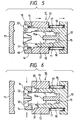
- Fig. 5 is a schematic cross-sectional view illustrating a state prior to tentative retention after molding by the molding and tentatively retaining mold.
- Fig. 6 is a schematic cross-sectional view illustrating a state during tentative retention by the molding and tentatively retaining mold.
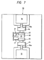
- Fig. 7 is a schematic plan view illustrating a state prior to tentative retention by a pair of rear-holder tentatively retaining cylinders of the molding and tentatively retaining mold.
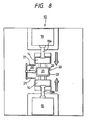
- Fig. 8 is a schematic plan view illustrating a state after the tentative retention by the rear-holder tentatively retaining cylinders of the molding and tentatively retaining mold.
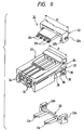
- Fig. 9 is an exploded perspective view illustrating a connector with rear holders.
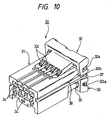
- Fig. 10 is a perspective view illustrating a state of tentative retention of the connector with rear holders in Fig. 9.
- a molding and tentatively retaining mold 10 is comprised of a fixed mold 11 and first to fourth movable molds 12, 13, 14, and 15, and compression springs 16 are interposed between the first movable mold 12 and the second movable molds 13, respectively. These compression springs 16 constantly urge the first and second movable molds 12 and 13 in directions in which they move away from each other (in the left- and rightward directions in Fig. 4).
- the movable molds 12, 13, 14, and 15 are respectively provided in such a manner as to be relatively movable with respect to the fixed mold 11, and mold a housing 31 and rear holders 32 and 33 of a connector 30 with rear holders respectively independently within a plurality of cavities 17 and 18 formed in cooperation with the fixed mold 11.
- the housing 31 and the rear holders 32 and 33 are set in a tentatively retained state.
- Inner surfaces of the first movable mold 12 and outer surfaces of the fourth movable mold 15 respectively form the cavity 17 for molding the housing 31 of the connector 30 with rear holders 30 in cooperation with inner surfaces of the fixed mold 11. Further, outer surfaces of the first movable mold 12 and inner surfaces of the third movable molds 14 respectively form the cavities 18 for molding the rear holders 32 and 33 of the connector 30 with rear holders in cooperation with the fixed mold 11.
- the second movable molds 13 support the first movable mold 12 movably along the left- and rightward directions in Fig. 4, and support the third movable molds 14 movably along the vertical direction in Fig. 4.
- the third movable molds 14 are moved toward the housing 31 side along the vertical directions in Fig. 4 so as to tentatively retain the rear holders 32 and 33 onto the housing 31.
- the fourth movable mold 15 is supported by the first movable mold 12, is movable in the left- and rightward directions in Fig. 4 in interlocking relation to the first movable mold 12, and holds the housing 31 during the tentative retention of the rear holders 32 and 33. Namely, when the rear holders 32 and 33 after molding are relatively moved with respect to the housing 31 by the third movable molds 14 and are tentatively retained, the fourth movable mold 15 moves in the rightward direction in Fig. 5 in interlocking relation to the movement of the first movable mold 12 in the same direction. At this juncture, a portion 15a of the fourth movable mold 15 for molding the cavity of the housing 31 is held as fitted to the housing 31 (in the state shown in Figs. 5 and 6).
- the fixed mold 11 and the movable molds 12, 13, 14, and 15 are provided with runners 20 and 21 serving as channels for the resin material to be charged for the respective cavities 17 and 18.
- the runners 20 and 21 have diameters which are set for the respective cavities 17 and 18 so as to obtain a molding balance in the cavities 17 and 18, respectively. Namely, the ratio of the diameter between the runners 20 and 21 is set to a value whereby the charging of the resin material into the cavities 17 and 18 is completed substantially at the same time.
- the diameter of the runner 20 for the cavity 17 in the housing 31 is set to about 4-fold in an area ratio with respect to the diameter of the runner 21 for the cavity 18 in each of the rear holders 32 and 33.
- the runner 20 for the cavity 17 in the housing 31 remains connected to the housing 31 through a tunnel gate 20a.
- the connection between the housing 31 and the tunnel gate 20a is cut off when the connector 30 with rear holders is removed from the mold after the tentative retention of the housing 31 and the rear holders 32 and 33.
- the runners 21 for the cavities 18 in the respective rear holders 32 and 33 are respectively located at parting lines between the fixed mold 11 and the movable molds 12, 13, 14, and 15. During molding, the runners 21 are connected to the rear holders 32 and 33 through tunnel gates 21a, respectively, and the connection is cut off in conjunction with the relative movement of the movable molds 12, 13, and 14 with respect to the fixed mold 11.
- the connector 30 with rear holders includes the housing 31 having a plurality of terminal accommodating chambers 34, as well as the pair of rear holders 32 and 33 which are retained on the upper and lower side surfaces, as viewed in Fig. 1, of the housing 31.
- Connecting terminals (not shown) attached to wires or the like are respectively inserted into the terminal accommodating chambers 34 of the housing 31, and are electrically connected thereto.
- Both left and right side surfaces, as viewed in Fig. 9, of the housing 31 are respectively provided with a pair of upper and lower tentatively retaining projections 35 (as viewed in Fig. 9) having tapered surfaces, a pair of upper and lower retaining steps 36 (as viewed in Fig. 9) formed in a tapered manner, a protecting rib 37, and a finally retaining projection 38.
- each tentatively retaining projection 35 on the upper side in Fig. 9 is fitted in a retaining hole 32a provided in the rear holder 32 on the upper side in Fig. 9 (hereafter, referred to as the upper rear holder 32), the upper tentatively retaining projection 35 tentatively retains the upper rear holder 32 onto the housing 31.
- the lower tentatively retaining projection 35 tentatively retains the lower rear holder 33 onto the housing 31.
- each retaining step 36 on the upper side in Fig. 9 is engaged with a retaining pawl 32b provided on the upper rear holder 32. Meanwhile, when the rear holders 32 and 33 are tentatively retained onto the housing 31 inside the molding and tentatively retaining mold 10, each retaining step 36 on the lower side in Fig. 9 is engaged with a retaining pawl 33b provided on the lower rear holder 33.
- the interval A between the protecting ribs 37 on both left and right sides surfaces, as viewed in Fig. 9, of the housing 31 is set to be larger than the transverse width B of each of the rear holders 32 and 33. Consequently, the rear holders 32 and 33 are prevented from coming off the housing 31 when the connector 30 with rear holders in the tentatively retained state is released from the mold.
- the connecting terminals inserted in the connector 30 with rear holders set in the tentatively retained state and released from the mold are primarily retained by housing lances (not shown) in the terminal accommodating chambers 34 in the housing 31, the finally retaining projections 38 are respectively fitted in the retaining holes 32a and 33a of the rear holders 32 and 33, so as to finally retain the rear holders 32 and 33 onto the housing 31.
- the connecting terminals are secondarily retained.
- the resin material is charged into the cavities 17 and 18 for molding the housing 31 and the rear holders 32 and 33 of the connector 30 with rear holders through the runners 20 and 21 corresponding to the cavities 17 and 18 in the state in which the fixed mold 11 and the movable molds 12, 13, 14, and 15 are joined together.
- the resin material is charged into the cavity 17 for the housing 31 from the runner 20 through a tunnel gate 20a, while the resin material is charged into the respective cavities 18 for the rear holders 32 and 33 from the runners 21 through tunnel gates 21a. Consequently, the housing 31 and the rear holders 32 and 33 are independently molded inside the cavities 17 and 18, respectively.
- the runner 20 for the cavity 17 in the housing 31 remains connected to the housing 31 through the tunnel gate 20a. Further, the portion 15a of the fourth movable mold 15 for forming the cavity in the housing 31 is held as fitted to the housing 31 (in the state shown in Figs. 5 and 6). Consequently, the shaking and the like of the housing 31 during tentative retention can be prevented.
- the resin material is first charged into the cavities 17 and 18 formed in the mold through the runners 20 and 21 corresponding to the cavities 17 and 18.
- the housing 31 and the rear holders 32 and 33 are respectively molded independently in the cavities 17 and 18.
- the movable molds 12, 13, 14, and 15 are respectively moved from the fixed mold 11 by predetermined amounts in the rightward direction in Fig. 5, and the first movable mold 12 is moved by a predetermined amount in the rightward direction in Fig. 5 with respect to the second movable molds 13 by the urging forces of the compression springs 16.
- the fourth movable mold 15 is relatively moved by a predetermined amount with respect to the second movable molds 13 in interlocking relation to the first movable mold 12 up to a position for forming cavities in a right end portion, as viewed in Fig. 5, of the molded housing 31 by a left end portion, as viewed in Fig. 5, of the fourth movable mold 15. Further, predetermined gap are formed on the inner sides of the third movable molds 14 by the movement of the first movable mold 12.
- the third movable molds 14 are respectively moved by the rear-holder tentatively retaining cylinders 19 in the directions of arrows in Figs. 6 and 8, so as to press the molded rear holders 32 and 33, respectively, toward the housing 31 and tentatively retain them onto the housing 31.
- the runner 20 for the cavity 17 in the housing 31 is kept in the state of being connected to the housing 31 through the tunnel gate 20a. Further, the portion 15a of the fourth movable mold 15 for forming the cavity in the housing 31 is held as fitted to the housing 31 (in the state shown in Figs. 5 and 6) . Consequently, the shaking and the like of the housing 31 during tentative retention is prevented.
- the runner 20 for the cavity 17 for molding the housing 31 remains connected to the housing 31 through the tunnel gate 20a, and the portion 15a of the fourth movable mold 15 for forming the cavity 17 in the housing 31 remains fitted to the housing 31 as it was during molding.
- the runner for the cavity for molding the other part remains connected to the other part through a tunnel gate.
- the connection between the other part and the tunnel gate is cut off when the parts are removed from the mold after the tentative retention of the parts.
- At least one part after molding is relatively moved with respect to the other part and is tentatively retained by movable molds, at least one movable mold for forming the cavity for forming the other part remains fitted to the other part as it was during molding.
Landscapes
- Engineering & Computer Science (AREA)
- Manufacturing & Machinery (AREA)
- Moulds For Moulding Plastics Or The Like (AREA)
- Injection Moulding Of Plastics Or The Like (AREA)
- Manufacturing Of Electrical Connectors (AREA)
Abstract
Description
- The present invention relates to a molding and tentatively retaining mold and a method of molding and tentative retention in which a plurality of kinds of independent parts of different shapes are molded in a plurality of cavities formed between a fixed mold and a plurality of movable molds, and at least one part after molding is relatively moved with respect to another part by the movable mold so as to set the parts in a tentatively retained state.
- The present application is based on Japanese Patent Application No. Hei. 11-361280, which is incorporated herein by reference.
- Referring to Fig. 11, as a conventional molding and tentatively retaining
mold 100 for effecting the molding and tentative retention of aconnector 110 with rear holders in its interior, JP-A-8-250183 discloses one which is comprised of an unillustrated fixed mold, a firstmovable mold 101 which is movable in vertical directions in Fig. 11, a pair of secondmovable molds 102 which are movable in left- and rightward directions in Fig. 11, and a pair of thirdmovable molds 103 which are movable in directions substantially perpendicular to the secondmovable molds 102. - It should be noted that the
connector 110 with rear holders is comprised of ahousing 111 having a plurality ofterminal accommodating chambers 113 and a pair ofrear holders 112 which are respectively retained on both sides of thehousing 111. - Inner surfaces of the first and second
movable molds housing 111 of theconnector 110 with rear holders in cooperation with the fixed mold. In addition, outer surfaces of the firstmovable mold 101, inner surfaces of the secondmovable molds 102, and inner surfaces of the thirdmovable molds 103 respectively form cavities for molding the respectiverear holders 112 of theconnector 110 with rear holders in cooperation with the fixed mold. - In the above-described molding and tentatively retaining
mold 100, when the molding and tentative retention of theconnector 110 with rear holders is effected, a resin material is charged into the respective cavities, for instance, from the upper direction in Fig. 11 through unillustrated runners for the respective cavities in a state in which the fixed mold and themovable molds - Namely, as shown in Fig. 12, the charging of the resin material into the cavities by using the runners is effected through a
pinpoint gate 114 in order to avoid the various mechanical parts inside the molds. - Consequently, the
housing 111 and therear holders 112 of theconnector 110 with rear holders are independently molded, respectively. - Next, the first
movable mold 101 is moved upwardly in Fig. 11, and the secondmovable molds 102 are respectively moved in the directions of arrows in Fig. 11. Consequently, predetermined gaps are respectively produced between the respectiverear holders 112 and thehousing 111. In this state, the thirdmovable molds 103 are respectively moved toward thehousing 111 so as to tentatively retain therear holders 112 onto the side surfaces of thehousing 111, respectively. - After the
housing 111 and therear holders 112 are tentatively retained, the thirdmovable molds 103 are respectively returned to their original positions. Then, theconnector 110 with rear holders in the tentatively retained state is removed from the mold. - With the above-described conventional molding and tentatively retaining
mold 100, there has been a problem in that when therear holders 112 are tentatively retained onto thehousing 111 after the molding of thehousing 111 and therear holders 112, trouble occurs in tentative retention owing to the shakiness or the like of thehousing 111. Accordingly, some means or other has been required for holding thehousing 111 after molding. - The object of the invention is to provide a molding and tentatively retaining mold and a method of molding and tentative retention which make it possible to reliably prevent the shakiness or the like of another part during tentative retention without especially requiring the means for holding the other part after molding, thereby making it possible to reliably effect the tentative retention of the parts.
- The above object of the invention can be attained by the following arrangements.
- (1) A molding and tentatively retaining mold comprising:
- a fixed mold;
- a plurality of movable molds provided in such a manner as to be relatively movable with respect to said fixed mold and adapted to respectively mold a plurality of kinds of independent parts of different shapes in a plurality of cavities formed in cooperation with said fixed mold, and to relatively move at least one part with respect to another part after molding to thereby set said parts in a tentatively retained state; and
- a plurality of runners respectively provided for the cavities to charge a molding material into the cavities;
- wherein, when at least one of said parts after molding is relatively moved with respect to said other part by said movable molds and is tentatively retained, a runner for a cavity for molding said other part remains connected to said other part through a tunnel gate, and
- the connection between said other part and said tunnel gate is cut off when said parts are removed from said mold after the tentative retention of said parts.
- (2) A molding and tentatively retaining mold comprising:
- a fixed mold;
- a plurality of movable molds provided in such a manner as to be relatively movable with respect to said fixed mold and adapted to respectively mold a plurality of kinds of independent parts of different shapes in a plurality of cavities formed in cooperation with said fixed mold, and to relatively move at least one part with respect to another part after molding to thereby set said parts in a tentatively retained state; and
- a plurality of runners respectively provided for the cavities to charge a molding material into the cavities;
- wherein, when at least one of said parts after molding is relatively moved with respect to said other part by said movable molds and is tentatively retained, at least one of said movable molds for forming a cavity for molding said other part remains fitted to said other part as it was during molding.
- (3) A method of molding and tentatively retaining,
comprising the steps of:
- forming a plurality of cavities between a fixed mold and a plurality of movable molds provided in such a manner as to be relatively movable with respect to said fixed mold;
- charging a molding material into said cavities through runners respectively provided for said cavities;
- molding a plurality of kinds of independent parts of different shapes in said cavities;
- moving relatively at least one of said movable molds with respect to said another movable mold to thereby tentatively retain at least one of said parts to said other part, keeping at least one of said runners for a cavity for molding said other part connected to said other part through a tunnel gate, and
- removing said parts from said mold to cut off the connection between said other part and said tunnel gate.
- (4) A method of molding and tentatively retaining,
comprising the steps of:
- forming a plurality of cavities between a fixed mold and a plurality of movable molds provided in such a manner as to be relatively movable with respect to said fixed mold;
- charging a molding material into said cavities through runners respectively provided for said cavities;
- molding a plurality of kinds of independent parts of different shapes in said of cavities; and
- moving relatively at least one of said movable molds with respect to said another movable mold to thereby tentatively retain at least one of said parts to said other part, while remaining at least one of said movable molds for molding said other part fitted to said other part as it was during molding.
-
- In the molding and tentatively retaining mold constructed in (1) above in accordance with the invention, a molding material is charged into a plurality of cavities formed between the fixed mold and the movable molds through runners. Consequently, a plurality of kinds of independent parts of different shapes are respectively molded in the cavities.
- After the molding of the respective parts, the movable mold relatively moves at least one part with respect to another part, thereby setting the parts in a tentatively retained state.
- At this juncture, the runner for the cavity for molding the other part remains connected to the other part through the tunnel gate. Consequently, the shakiness and the like of the other part during tentative retention can be prevented. The connection between the other part and the tunnel gate is cut off as the parts are removed from the mold after the tentative retention of the parts.
- In the molding and tentatively retaining mold constructed in (2) above in accordance with the invention, a molding material is charged into a plurality of cavities formed between the fixed mold and the movable molds through runners. Consequently, a plurality of kinds of independent parts of different shapes are respectively molded in the cavities.
- After the molding of the respective parts, the movable mold relatively moves at least one part with respect to another part, thereby setting the parts in a tentatively retained state.
- At this juncture, at least one of the movable molds for forming the cavity for molding the other part remains fitted to the other part as it was during molding. Consequently, the shakiness and the like of the other part during tentative retention can be prevented.
- In the method of molding and tentative retention arranged in (3) above in accordance with the invention, a molding material is charged into a plurality of cavities formed between a fixed mold and a plurality of movable molds provided in such a manner as to be relatively movable with respect to the fixed mold, through runners respectively provided for the cavities. Consequently, a plurality of kinds of independent parts of different shapes are respectively molded in the cavities.
- Next, at least one part after molding is relatively moved with respect to another part, thereby setting the parts in a tentatively retained state.
- At this juncture, the runner for the cavity for molding the other part is kept connected to the other part through the tunnel gate. Consequently, the shakiness and the like of the other part during tentative retention is prevented. The connection between the other part and the tunnel gate is cut off as the parts are removed from the mold after the tentative retention of the parts.
- In the method of molding and tentative retention arranged in (4) above in accordance with the invention, a molding material is charged into a plurality of cavities formed between a fixed mold and a plurality of movable molds provided in such a manner as to be relatively movable with respect to the fixed mold, through runners respectively provided for the cavities. Consequently, a plurality of kinds of independent parts of different shapes are respectively molded in the cavities.
- Next, at least one part after molding is relatively moved with respect to another part, thereby setting the parts in a tentatively retained state.
- At this juncture, at least one of the movable molds for forming the cavity for molding the other part is kept fitted to the other part as it was during molding. Consequently, the shakiness and the like of the other part during tentative retention is prevented.
-
- Fig. 1 is a schematic plan view illustrating runners for cavities of a molding and tentatively retaining mold and a connector with rear holders in accordance with an embodiment of the invention;
- Fig. 2 is a schematic cross-sectional view of Fig. 1;
- Fig. 3 is a plan view schematically representing Fig. 1;
- Fig. 4 is a schematic cross-sectional view illustrating a state during molding by the molding and tentatively retaining mold;
- Fig. 5 is a schematic cross-sectional view illustrating a state prior to tentative retention after molding by the molding and tentatively retaining mold;
- Fig. 6 is a schematic cross-sectional view illustrating a state during tentative retention by the molding and tentatively retaining mold;
- Fig. 7 is a schematic plan view illustrating a state prior to tentative retention by a pair of rear-holder tentatively retaining cylinders of the molding and tentatively retaining mold;
- Fig. 8 is a schematic plan view illustrating a state after the tentative retention by the rear-holder tentatively retaining cylinders of the molding and tentatively retaining mold;
- Fig. 9 is an exploded perspective view illustrating a connector with rear holders;
- Fig. 10 is a perspective view illustrating a state of tentative retention of the connector with rear holders in Fig. 9;
- Fig. 11 is a schematic perspective view illustrating a conventional molding and tentatively retaining mold; and
- Fig. 12 is a schematic cross-sectional view illustrating a pinpoint gate of the molding and tentatively retaining mold and the connector with rear holders shown in Fig. 11.
-
- Referring now to the drawings, a description will be given of an embodiment of the invention.
- Fig. 1 is a schematic plan view illustrating runners for cavities and a connector with rear holders of a molding and tentatively retaining mold in accordance with an embodiment of the invention. Fig. 2 is a schematic cross-sectional view of Fig. 1, and Fig. 3 is a plan view schematically illustrating Fig. 1.
- In addition, Fig. 4 is a schematic cross-sectional view illustrating a state during molding by the molding and tentatively retaining mold. Fig. 5 is a schematic cross-sectional view illustrating a state prior to tentative retention after molding by the molding and tentatively retaining mold. Fig. 6 is a schematic cross-sectional view illustrating a state during tentative retention by the molding and tentatively retaining mold. Fig. 7 is a schematic plan view illustrating a state prior to tentative retention by a pair of rear-holder tentatively retaining cylinders of the molding and tentatively retaining mold. Fig. 8 is a schematic plan view illustrating a state after the tentative retention by the rear-holder tentatively retaining cylinders of the molding and tentatively retaining mold.
- Further, Fig. 9 is an exploded perspective view illustrating a connector with rear holders. Fig. 10 is a perspective view illustrating a state of tentative retention of the connector with rear holders in Fig. 9.
- Referring to Figs. 1 to 8, a molding and tentatively retaining
mold 10 is comprised of a fixedmold 11 and first to fourthmovable molds movable mold 12 and the secondmovable molds 13, respectively. These compression springs 16 constantly urge the first and secondmovable molds - The
movable molds mold 11, and mold ahousing 31 andrear holders connector 30 with rear holders respectively independently within a plurality ofcavities mold 11. As therear holders housing 31, thehousing 31 and therear holders - Inner surfaces of the first
movable mold 12 and outer surfaces of the fourthmovable mold 15 respectively form thecavity 17 for molding thehousing 31 of theconnector 30 withrear holders 30 in cooperation with inner surfaces of the fixedmold 11. Further, outer surfaces of the firstmovable mold 12 and inner surfaces of the thirdmovable molds 14 respectively form thecavities 18 for molding therear holders connector 30 with rear holders in cooperation with the fixedmold 11. - The second
movable molds 13 support the firstmovable mold 12 movably along the left- and rightward directions in Fig. 4, and support the thirdmovable molds 14 movably along the vertical direction in Fig. 4. - As a pair of
cylinder rods 19a of a pair of rear-holder tentatively retaining cylinders 19 (see Figs. 7 and 8) project, the thirdmovable molds 14 are moved toward thehousing 31 side along the vertical directions in Fig. 4 so as to tentatively retain therear holders housing 31. - The fourth
movable mold 15 is supported by the firstmovable mold 12, is movable in the left- and rightward directions in Fig. 4 in interlocking relation to the firstmovable mold 12, and holds thehousing 31 during the tentative retention of therear holders rear holders housing 31 by the thirdmovable molds 14 and are tentatively retained, the fourthmovable mold 15 moves in the rightward direction in Fig. 5 in interlocking relation to the movement of the firstmovable mold 12 in the same direction. At this juncture, aportion 15a of the fourthmovable mold 15 for molding the cavity of thehousing 31 is held as fitted to the housing 31 (in the state shown in Figs. 5 and 6). - The fixed
mold 11 and themovable molds runners respective cavities - The
runners respective cavities cavities runners cavities runner 20 for thecavity 17 in thehousing 31 is set to about 4-fold in an area ratio with respect to the diameter of therunner 21 for thecavity 18 in each of therear holders - When the
rear holders housing 31 by themovable molds runner 20 for thecavity 17 in thehousing 31 remains connected to thehousing 31 through atunnel gate 20a. The connection between thehousing 31 and thetunnel gate 20a is cut off when theconnector 30 with rear holders is removed from the mold after the tentative retention of thehousing 31 and therear holders - Further, the
runners 21 for thecavities 18 in the respectiverear holders mold 11 and themovable molds runners 21 are connected to therear holders tunnel gates 21a, respectively, and the connection is cut off in conjunction with the relative movement of themovable molds mold 11. - Next, referring to Figs. 9 and 10, a detailed description will be given of the
connector 30 with rear holders. - Namely, the
connector 30 with rear holders includes thehousing 31 having a plurality of terminalaccommodating chambers 34, as well as the pair ofrear holders housing 31. Connecting terminals (not shown) attached to wires or the like are respectively inserted into the terminalaccommodating chambers 34 of thehousing 31, and are electrically connected thereto. - Both left and right side surfaces, as viewed in Fig. 9, of the
housing 31 are respectively provided with a pair of upper and lower tentatively retaining projections 35 (as viewed in Fig. 9) having tapered surfaces, a pair of upper and lower retaining steps 36 (as viewed in Fig. 9) formed in a tapered manner, a protectingrib 37, and a finally retainingprojection 38. - As each tentatively retaining
projection 35 on the upper side in Fig. 9 is fitted in a retaininghole 32a provided in therear holder 32 on the upper side in Fig. 9 (hereafter, referred to as the upper rear holder 32), the upper tentatively retainingprojection 35 tentatively retains the upperrear holder 32 onto thehousing 31. Meanwhile, as each tentatively retainingprojection 35 on the lower side in Fig. 9 is fitted in a retaininghole 33a provided in therear holder 33 on the lower side in Fig. 9 (hereafter, referred to as the lower rear holder 33), the lower tentatively retainingprojection 35 tentatively retains the lowerrear holder 33 onto thehousing 31. - when the
rear holders housing 31 inside the molding and tentatively retainingmold 10, each retainingstep 36 on the upper side in Fig. 9 is engaged with a retainingpawl 32b provided on the upperrear holder 32. Meanwhile, when therear holders housing 31 inside the molding and tentatively retainingmold 10, each retainingstep 36 on the lower side in Fig. 9 is engaged with a retaining pawl 33b provided on the lowerrear holder 33. - The interval A between the protecting
ribs 37 on both left and right sides surfaces, as viewed in Fig. 9, of thehousing 31 is set to be larger than the transverse width B of each of therear holders rear holders housing 31 when theconnector 30 with rear holders in the tentatively retained state is released from the mold. - Further, when the connecting terminals inserted in the
connector 30 with rear holders set in the tentatively retained state and released from the mold are primarily retained by housing lances (not shown) in the terminalaccommodating chambers 34 in thehousing 31, the finally retainingprojections 38 are respectively fitted in the retainingholes rear holders rear holders housing 31. In this state, as secondarily retainingprojections rear holders accommodating chambers 34 of thehousing 31, the connecting terminals are secondarily retained. - A description will be given of the operation in accordance with this embodiment.
- In the molding and tentatively retaining
mold 10, the resin material is charged into thecavities housing 31 and therear holders connector 30 with rear holders through therunners cavities mold 11 and themovable molds - Namely, the resin material is charged into the
cavity 17 for thehousing 31 from therunner 20 through atunnel gate 20a, while the resin material is charged into therespective cavities 18 for therear holders runners 21 throughtunnel gates 21a. Consequently, thehousing 31 and therear holders cavities - As the
movable molds mold 11 after the molding of thehousing 31 and therear holders runners 21 for thecavities 18 in therear holders rear holders tunnel gates 21a are respectively cut off. - In this state, as the third
movable molds 14 relatively move therear holders housing 31, theconnector 30 with rear holders is set in a tentatively retained state. - At this juncture, the
runner 20 for thecavity 17 in thehousing 31 remains connected to thehousing 31 through thetunnel gate 20a. Further, theportion 15a of the fourthmovable mold 15 for forming the cavity in thehousing 31 is held as fitted to the housing 31 (in the state shown in Figs. 5 and 6). Consequently, the shaking and the like of thehousing 31 during tentative retention can be prevented. - Referring now to Figs. 4 to 8, a description will be given of a method of molding and tentatively retaining a
connector 30 with rear holders by using the molding and tentatively retainingmold 10 in accordance with this embodiment. - Referring to Fig. 4, in the state in which the fixed
mold 11 and themovable molds cavities runners cavities housing 31 and therear holders cavities - At this juncture, since the diameters of the
runners respective cavities respective cavities - Next, referring to Fig. 5, the
movable molds mold 11 by predetermined amounts in the rightward direction in Fig. 5, and the firstmovable mold 12 is moved by a predetermined amount in the rightward direction in Fig. 5 with respect to the secondmovable molds 13 by the urging forces of the compression springs 16. - At this juncture, the fourth
movable mold 15 is relatively moved by a predetermined amount with respect to the secondmovable molds 13 in interlocking relation to the firstmovable mold 12 up to a position for forming cavities in a right end portion, as viewed in Fig. 5, of the moldedhousing 31 by a left end portion, as viewed in Fig. 5, of the fourthmovable mold 15. Further, predetermined gap are formed on the inner sides of the thirdmovable molds 14 by the movement of the firstmovable mold 12. - Further, referring to Figs. 6 to 8, the third
movable molds 14 are respectively moved by the rear-holder tentatively retainingcylinders 19 in the directions of arrows in Figs. 6 and 8, so as to press the moldedrear holders housing 31 and tentatively retain them onto thehousing 31. - Namely, as the
rear holders movable molds 14 in the directions of arrows in Figs. 6 and 8, the tentatively retainingprojections 35 of thehousing 31 are fitted in the retainingholes pows 32b and 33b are fitted to the retaining means 36. Consequently, therear holders housing 31. - At this juncture, the
runner 20 for thecavity 17 in thehousing 31 is kept in the state of being connected to thehousing 31 through thetunnel gate 20a. Further, theportion 15a of the fourthmovable mold 15 for forming the cavity in thehousing 31 is held as fitted to the housing 31 (in the state shown in Figs. 5 and 6) . Consequently, the shaking and the like of thehousing 31 during tentative retention is prevented. - As described above, in accordance with the above-described embodiment, when the
rear holders housing 31 by themovable molds runner 20 for thecavity 17 for molding thehousing 31 remains connected to thehousing 31 through thetunnel gate 20a, and theportion 15a of the fourthmovable mold 15 for forming thecavity 17 in thehousing 31 remains fitted to thehousing 31 as it was during molding. - Accordingly, while it is possible to attain the simplification of the mold structure without especially requiring a means for holding the
housing 31 after molding, it is possible to reliably prevent the shaking and the like of thehousing 31 during tentative retention of therear holders housing 31. Consequently, the tentative retention of therear holders housing 31 can be effected reliably. - As described above, in accordance with the invention, when at least one part after molding is relatively moved with respect to another part by movable molds and is tentatively retained, the runner for the cavity for molding the other part remains connected to the other part through a tunnel gate. The connection between the other part and the tunnel gate is cut off when the parts are removed from the mold after the tentative retention of the parts.
- Accordingly, it is possible to reliably prevent the shaking and the like of the other part during tentative retention without especially requiring a means for holding the other part after molding. Consequently, the tentative retention of the respective parts can be effected reliably.
- In addition, in accordance with the invention, when at least one part after molding is relatively moved with respect to the other part and is tentatively retained by movable molds, at least one movable mold for forming the cavity for forming the other part remains fitted to the other part as it was during molding.
- Accordingly, it is possible to reliably prevent the shaking and the like of the other part during tentative retention without especially requiring a means for holding the other part after molding. Consequently, the tentative retention of the respective parts can be effected reliably.
Claims (4)
- A molding and tentatively retaining mold comprising:a fixed mold;a plurality of movable molds provided in such a manner as to be relatively movable with respect to said fixed mold and adapted to respectively mold a plurality of kinds of independent parts of different shapes in a plurality of cavities formed in cooperation with said fixed mold, and to relatively move at least one part with respect to another part after molding to thereby set said parts in a tentatively retained state; anda plurality of runners respectively provided for the cavities to charge a molding material into the cavities;wherein, when at least one of said parts after molding is relatively moved with respect to said other part by said movable molds and is tentatively retained, a runner for a cavity for molding said other part remains connected to said other part through a tunnel gate, andthe connection between said other part and said tunnel gate is cut off when said parts are removed from said mold after the tentative retention of said parts.
- A molding and tentatively retaining mold comprising:a fixed mold;a plurality of movable molds provided in such a manner as to be relatively movable with respect to said fixed mold and adapted to respectively mold a plurality of kinds of independent parts of different shapes in a plurality of cavities formed in cooperation with said fixed mold, and to relatively move at least one part with respect to another part after molding to thereby set said parts in a tentatively retained state; anda plurality of runners respectively provided for the cavities to charge a molding material into the cavities;wherein, when at least one of said parts after molding is relatively moved with respect to said other part by said movable molds and is tentatively retained, at least one of said movable molds for molding said other part remains fitted to said other part as it was during molding.
- A method of molding and tentatively retaining, comprising the steps of:forming a plurality of cavities between a fixed mold and a plurality of movable molds provided in such a manner as to be relatively movable with respect to said fixed mold;charging a molding material into said cavities through runners respectively provided for said cavities;molding a plurality of kinds of independent parts of different shapes in said cavities;moving relatively at least one of said movable molds with respect to said another movable mold to thereby tentatively retain at least one of said parts to said other part, while keeping at least one of said runners for a cavity for molding said other part connected to said other part through a tunnel gate, andremoving said parts from said mold to thereby cut off the connection between said other part and said tunnel gate.
- A method of molding and tentatively retaining, comprising the steps of:forming a plurality of cavities between a fixed mold and a plurality of movable molds provided in such a manner as to be relatively movable with respect to said fixed mold;charging a molding material into said cavities through runners respectively provided for said cavities;molding a plurality of kinds of independent parts of different shapes in said of cavities; andmoving relatively at least one of said movable molds with respect to said another movable mold to thereby tentatively retain at least one of said parts to said other part, while remaining at least one of said movable molds for molding said other part fitted to said other part as it was during molding.
Applications Claiming Priority (2)
| Application Number | Priority Date | Filing Date | Title |
|---|---|---|---|
| JP36128099 | 1999-12-20 | ||
| JP36128099A JP3625167B2 (en) | 1999-12-20 | 1999-12-20 | Molding temporary locking mold and molding temporary locking method |
Publications (2)
| Publication Number | Publication Date |
|---|---|
| EP1111737A1 true EP1111737A1 (en) | 2001-06-27 |
| EP1111737B1 EP1111737B1 (en) | 2004-07-14 |
Family
ID=18472931
Family Applications (1)
| Application Number | Title | Priority Date | Filing Date |
|---|---|---|---|
| EP00311395A Expired - Lifetime EP1111737B1 (en) | 1999-12-20 | 2000-12-19 | Molding and tentatively retaining mold and method of molding and tentative retention |
Country Status (5)
| Country | Link |
|---|---|
| US (1) | US6596211B2 (en) |
| EP (1) | EP1111737B1 (en) |
| JP (1) | JP3625167B2 (en) |
| DE (1) | DE60012123T2 (en) |
| PT (1) | PT1111737E (en) |
Families Citing this family (5)
| Publication number | Priority date | Publication date | Assignee | Title |
|---|---|---|---|---|
| JP3690785B2 (en) * | 1999-08-24 | 2005-08-31 | 矢崎総業株式会社 | Connector with rear holder and manufacturing method thereof |
| JP3625168B2 (en) * | 1999-12-20 | 2005-03-02 | 矢崎総業株式会社 | Molding temporary locking mold and molding temporary locking method |
| JP3859215B2 (en) * | 2003-02-06 | 2006-12-20 | 株式会社小糸製作所 | Molding method and molding apparatus for resin parts for vehicle lamp |
| CN103640127B (en) * | 2013-12-09 | 2016-07-06 | 安徽宁国中鼎模具制造有限公司 | A kind of automobile guiding pin dust-proof cover die |
| US10507600B2 (en) | 2015-09-14 | 2019-12-17 | Bell Helicopter Textron Inc. | Modular tooling for manufacturing multi-cavity composite structures |
Citations (2)
| Publication number | Priority date | Publication date | Assignee | Title |
|---|---|---|---|---|
| EP0732780A2 (en) * | 1995-03-15 | 1996-09-18 | SUMITOMO WIRING SYSTEMS, Ltd. | Connector manufacturing method and metal mold therefore |
| US5911935A (en) * | 1995-04-24 | 1999-06-15 | Sumitomo Wiring Systems, Ltd. | Method for manufacturing a connector and a retainer |
Family Cites Families (8)
| Publication number | Priority date | Publication date | Assignee | Title |
|---|---|---|---|---|
| US3013308A (en) * | 1957-10-08 | 1961-12-19 | Plax Corp | Method for molding and assembling dispenser fitment |
| US4012827A (en) * | 1975-06-09 | 1977-03-22 | Gilbert Lawrence Abrams | Method for molding composite articles |
| JPS57135133A (en) * | 1981-02-14 | 1982-08-20 | Matsushita Electric Works Ltd | Simultaneous forming process for plural parts with coaxial structure and apparatus therefor |
| US5200132A (en) * | 1987-03-31 | 1993-04-06 | Plastro Gvat | Method and an apparatus for producing a drip-irrigation emitter |
| JP3000883B2 (en) | 1995-03-13 | 2000-01-17 | 住友電装株式会社 | connector |
| US5915760A (en) * | 1995-03-16 | 1999-06-29 | Sumitomo Wiring Systems, Ltd. | Method of producing resin-molded product |
| JP3266782B2 (en) * | 1995-06-05 | 2002-03-18 | 矢崎総業株式会社 | Manufacturing method of connector with rear holder |
| DK172527B1 (en) * | 1996-11-21 | 1998-11-23 | C Hansen Vaerktoejsfabrik As A | Injection molding tool for making a bucket with a swivel handle |
-
1999
- 1999-12-20 JP JP36128099A patent/JP3625167B2/en not_active Expired - Fee Related
-
2000
- 2000-12-19 EP EP00311395A patent/EP1111737B1/en not_active Expired - Lifetime
- 2000-12-19 PT PT00311395T patent/PT1111737E/en unknown
- 2000-12-19 DE DE60012123T patent/DE60012123T2/en not_active Expired - Lifetime
- 2000-12-20 US US09/739,652 patent/US6596211B2/en not_active Expired - Lifetime
Patent Citations (2)
| Publication number | Priority date | Publication date | Assignee | Title |
|---|---|---|---|---|
| EP0732780A2 (en) * | 1995-03-15 | 1996-09-18 | SUMITOMO WIRING SYSTEMS, Ltd. | Connector manufacturing method and metal mold therefore |
| US5911935A (en) * | 1995-04-24 | 1999-06-15 | Sumitomo Wiring Systems, Ltd. | Method for manufacturing a connector and a retainer |
Also Published As
| Publication number | Publication date |
|---|---|
| DE60012123D1 (en) | 2004-08-19 |
| US20010015511A1 (en) | 2001-08-23 |
| JP3625167B2 (en) | 2005-03-02 |
| DE60012123T2 (en) | 2005-08-25 |
| EP1111737B1 (en) | 2004-07-14 |
| US6596211B2 (en) | 2003-07-22 |
| JP2001170973A (en) | 2001-06-26 |
| PT1111737E (en) | 2004-10-29 |
Similar Documents
| Publication | Publication Date | Title |
|---|---|---|
| US5926952A (en) | Method of fabricating a connector using a pre-molded connector structure | |
| KR101418665B1 (en) | Method for producing resin molded article by injection molding, and injection molding device | |
| US5038468A (en) | Method of insert molding with web placed in the mold | |
| US20010013672A1 (en) | Molding and tentatively retaining mold and method of molding and tentative retention | |
| EP1113535B1 (en) | Connector having rear holders and method of manufacturing thereof | |
| EP1111737B1 (en) | Molding and tentatively retaining mold and method of molding and tentative retention | |
| US8253519B2 (en) | Coil former and coil body for an electromagnetic relay | |
| US6705854B2 (en) | Rear holder-attached connector and method of producing the same | |
| EP1110704B1 (en) | Method of molding and tentative retention | |
| JP3147753B2 (en) | Mold and method for manufacturing resin molded assembly | |
| JPH05134142A (en) | Optical fiber connector | |
| JP4484128B2 (en) | Injection molding method and injection molding apparatus | |
| US6416700B1 (en) | Method of producing resin-molded assembly and method producing double-retaining connector | |
| US6536108B2 (en) | Method of and apparatus for producing rear holder-attached connector | |
| JP3278366B2 (en) | Method of manufacturing resin assembly and method of manufacturing double locking connector | |
| JPH0989165A (en) | Binding band forming method and binding band | |
| JP2530555B2 (en) | Power connector | |
| JP3518167B2 (en) | Waterproof connector and manufacturing method thereof | |
| JP4014141B2 (en) | Injection molding body manufacturing equipment | |
| JP3250214B2 (en) | Method of manufacturing waterproof connector and mold for manufacturing the same | |
| JPH11144793A (en) | Waterproof connector, manufacture thereof and die for manufacture | |
| JP2003011178A (en) | Mold for molding a lead storage battery | |
| JPH0588493B2 (en) | ||
| JPH10109329A (en) | Injection mold | |
| JP2000166166A (en) | Motor |
Legal Events
| Date | Code | Title | Description |
|---|---|---|---|
| PUAI | Public reference made under article 153(3) epc to a published international application that has entered the european phase |
Free format text: ORIGINAL CODE: 0009012 |
|
| AK | Designated contracting states |
Kind code of ref document: A1 Designated state(s): DE FR GB PT |
|
| AX | Request for extension of the european patent |
Free format text: AL;LT;LV;MK;RO;SI |
|
| 17P | Request for examination filed |
Effective date: 20011205 |
|
| AKX | Designation fees paid |
Free format text: DE FR GB PT |
|
| 17Q | First examination report despatched |
Effective date: 20030530 |
|
| GRAP | Despatch of communication of intention to grant a patent |
Free format text: ORIGINAL CODE: EPIDOSNIGR1 |
|
| GRAS | Grant fee paid |
Free format text: ORIGINAL CODE: EPIDOSNIGR3 |
|
| GRAA | (expected) grant |
Free format text: ORIGINAL CODE: 0009210 |
|
| AK | Designated contracting states |
Kind code of ref document: B1 Designated state(s): DE FR GB PT |
|
| REG | Reference to a national code |
Ref country code: GB Ref legal event code: FG4D |
|
| REF | Corresponds to: |
Ref document number: 60012123 Country of ref document: DE Date of ref document: 20040819 Kind code of ref document: P |
|
| REG | Reference to a national code |
Ref country code: PT Ref legal event code: SC4A Free format text: AVAILABILITY OF NATIONAL TRANSLATION Effective date: 20040907 |
|
| ET | Fr: translation filed | ||
| PLBE | No opposition filed within time limit |
Free format text: ORIGINAL CODE: 0009261 |
|
| STAA | Information on the status of an ep patent application or granted ep patent |
Free format text: STATUS: NO OPPOSITION FILED WITHIN TIME LIMIT |
|
| 26N | No opposition filed |
Effective date: 20050415 |
|
| PGFP | Annual fee paid to national office [announced via postgrant information from national office to epo] |
Ref country code: GB Payment date: 20141217 Year of fee payment: 15 |
|
| PGFP | Annual fee paid to national office [announced via postgrant information from national office to epo] |
Ref country code: FR Payment date: 20141208 Year of fee payment: 15 |
|
| GBPC | Gb: european patent ceased through non-payment of renewal fee |
Effective date: 20151219 |
|
| REG | Reference to a national code |
Ref country code: FR Ref legal event code: ST Effective date: 20160831 |
|
| PG25 | Lapsed in a contracting state [announced via postgrant information from national office to epo] |
Ref country code: GB Free format text: LAPSE BECAUSE OF NON-PAYMENT OF DUE FEES Effective date: 20151219 |
|
| PG25 | Lapsed in a contracting state [announced via postgrant information from national office to epo] |
Ref country code: FR Free format text: LAPSE BECAUSE OF NON-PAYMENT OF DUE FEES Effective date: 20151231 |
|
| PGFP | Annual fee paid to national office [announced via postgrant information from national office to epo] |
Ref country code: PT Payment date: 20191219 Year of fee payment: 20 Ref country code: DE Payment date: 20191203 Year of fee payment: 20 |
|
| REG | Reference to a national code |
Ref country code: DE Ref legal event code: R071 Ref document number: 60012123 Country of ref document: DE |
|
| PG25 | Lapsed in a contracting state [announced via postgrant information from national office to epo] |
Ref country code: PT Free format text: LAPSE BECAUSE OF EXPIRATION OF PROTECTION Effective date: 20210104 |