EP1111728A2 - Connector with an improved guide portion for guiding connection of the connector and an object to be connected thereto - Google Patents
Connector with an improved guide portion for guiding connection of the connector and an object to be connected thereto Download PDFInfo
- Publication number
- EP1111728A2 EP1111728A2 EP00127483A EP00127483A EP1111728A2 EP 1111728 A2 EP1111728 A2 EP 1111728A2 EP 00127483 A EP00127483 A EP 00127483A EP 00127483 A EP00127483 A EP 00127483A EP 1111728 A2 EP1111728 A2 EP 1111728A2
- Authority
- EP
- European Patent Office
- Prior art keywords
- connector
- hood
- guide portion
- mating
- insulator
- Prior art date
- Legal status (The legal status is an assumption and is not a legal conclusion. Google has not performed a legal analysis and makes no representation as to the accuracy of the status listed.)
- Granted
Links
Images





Classifications
-
- H—ELECTRICITY
- H01—ELECTRIC ELEMENTS
- H01R—ELECTRICALLY-CONDUCTIVE CONNECTIONS; STRUCTURAL ASSOCIATIONS OF A PLURALITY OF MUTUALLY-INSULATED ELECTRICAL CONNECTING ELEMENTS; COUPLING DEVICES; CURRENT COLLECTORS
- H01R13/00—Details of coupling devices of the kinds covered by groups H01R12/70 or H01R24/00 - H01R33/00
- H01R13/02—Contact members
- H01R13/04—Pins or blades for co-operation with sockets
- H01R13/05—Resilient pins or blades
-
- H—ELECTRICITY
- H01—ELECTRIC ELEMENTS
- H01R—ELECTRICALLY-CONDUCTIVE CONNECTIONS; STRUCTURAL ASSOCIATIONS OF A PLURALITY OF MUTUALLY-INSULATED ELECTRICAL CONNECTING ELEMENTS; COUPLING DEVICES; CURRENT COLLECTORS
- H01R13/00—Details of coupling devices of the kinds covered by groups H01R12/70 or H01R24/00 - H01R33/00
- H01R13/62—Means for facilitating engagement or disengagement of coupling parts or for holding them in engagement
- H01R13/627—Snap or like fastening
- H01R13/6275—Latching arms not integral with the housing
-
- H—ELECTRICITY
- H01—ELECTRIC ELEMENTS
- H01R—ELECTRICALLY-CONDUCTIVE CONNECTIONS; STRUCTURAL ASSOCIATIONS OF A PLURALITY OF MUTUALLY-INSULATED ELECTRICAL CONNECTING ELEMENTS; COUPLING DEVICES; CURRENT COLLECTORS
- H01R13/00—Details of coupling devices of the kinds covered by groups H01R12/70 or H01R24/00 - H01R33/00
- H01R13/62—Means for facilitating engagement or disengagement of coupling parts or for holding them in engagement
- H01R13/629—Additional means for facilitating engagement or disengagement of coupling parts, e.g. aligning or guiding means, levers, gas pressure electrical locking indicators, manufacturing tolerances
- H01R13/631—Additional means for facilitating engagement or disengagement of coupling parts, e.g. aligning or guiding means, levers, gas pressure electrical locking indicators, manufacturing tolerances for engagement only
- H01R13/6315—Additional means for facilitating engagement or disengagement of coupling parts, e.g. aligning or guiding means, levers, gas pressure electrical locking indicators, manufacturing tolerances for engagement only allowing relative movement between coupling parts, e.g. floating connection
-
- H—ELECTRICITY
- H01—ELECTRIC ELEMENTS
- H01R—ELECTRICALLY-CONDUCTIVE CONNECTIONS; STRUCTURAL ASSOCIATIONS OF A PLURALITY OF MUTUALLY-INSULATED ELECTRICAL CONNECTING ELEMENTS; COUPLING DEVICES; CURRENT COLLECTORS
- H01R13/00—Details of coupling devices of the kinds covered by groups H01R12/70 or H01R24/00 - H01R33/00
- H01R13/02—Contact members
- H01R13/22—Contacts for co-operating by abutting
- H01R13/24—Contacts for co-operating by abutting resilient; resiliently-mounted
- H01R13/2407—Contacts for co-operating by abutting resilient; resiliently-mounted characterized by the resilient means
- H01R13/2421—Contacts for co-operating by abutting resilient; resiliently-mounted characterized by the resilient means using coil springs
-
- H—ELECTRICITY
- H01—ELECTRIC ELEMENTS
- H01R—ELECTRICALLY-CONDUCTIVE CONNECTIONS; STRUCTURAL ASSOCIATIONS OF A PLURALITY OF MUTUALLY-INSULATED ELECTRICAL CONNECTING ELEMENTS; COUPLING DEVICES; CURRENT COLLECTORS
- H01R2201/00—Connectors or connections adapted for particular applications
- H01R2201/16—Connectors or connections adapted for particular applications for telephony
Definitions
- This invention relates to a connector having a guide portion for guiding connection of the connector and an object to be connected thereto.
- a connector of the type having a guide portion is disclosed, for example, in Japanese Unexamined Patent Publications (JP-A) Nos. H07-335296 and H09-320684.
- the guide portion is formed as a part integral with an insulator made of a hard material and holding a contact.
- a mobile telephone is provided with a connector to be used when a battery is charged.
- the contact used in the connector is of a butt-contact type in which the contact and a mating contact of a mating connector as an object are pressed against each other in a predetermined direction.
- the insulator is provided with a lock mechanism for stably holding the contact and the mating contact in a contacting state.
- the connector of the above-mentioned structure is connected to the mating connector and thereafter disconnected therefrom without releasing the lock mechanism.
- an excessive force may be applied in a direction perpendicular to the predetermined direction, so that the insulator is damaged, for example, cracked. This is because the insulator is poor in flexibility.
- a connector having a principal surface to be faced to an object in a first direction and a guide portion protruding from the principal surface in the first direction for guiding connection of the connector and the object, wherein the guide portion has elasticity so as to be elastically bent in a second direction transverse to the first direction.
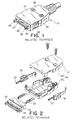
- a connector illustrated in Figs. 1 and 2 is a plug connector 21 comprising a plurality of electroconductive contacts 22, an insulator 23 holding the contacts 22, and a hood 24 covering the insulator 23.
- the insulator 23 has a pair of guide portions 25 protruding from positions near to opposite ends thereof to be in parallel to each other.
- Each of the guide portions 25 is made of a heat-resistant hard material and formed as an integral part integral with the insulator 23.
- the guide portions 25 serve to guide coupling of the plug connector 21 and a mating connector which will later be described.
- Each of the guide portions 25 is provided with a slide groove for receiving a locking claw 27 connected to a lock mechanism operating portion 26.
- the hood 24 comprises a pair of hood components 28 butted to each other and fixed by a fixture such as a screw.
- the lock mechanism operating portion 26 is movably held by the hood 24.
- the mating connector is a receptacle connector 31 to be coupled and connected to the plug connector 21 in Figs. 1 and 2 in a first direction.
- the receptacle connector 31 comprises an insulator 32 and a plurality of electroconductive mating contacts 33 held between opposite ends 32a and 32b of the insulator 32.
- the insulator 32 is provided with a pair of recessed portions 34 formed at the opposite ends 32a and 32b for receiving the guide portions 25, respectively. To each of the recessed portions 34, a lock plate 35 is fixed. The lock plate 35 has a locking hole 36 to be engaged with the locking claw 27 of the plug connector 21.
- the recessed portion 34 has an internal dimension H1 greater than an external dimension H2 of the guide portion 25. Therefore, as illustrated in Fig. 6, a gap is formed between the inner surface of the recessed portion 34 and the outer surface of the guide portion 25 when the plug connector 21 is coupled to the mating connector 31. Due to the presence of the gap, mutual contact between the contacts 22 and the mating contacts 33 is unstable.
- the guide portion 25 is made of the heat-resistant hard material and formed as the integral part integral with the insulator 23, the guide portion 25 is poor in flexibility. Therefore, if the plug connector 21 is subjected to an external force as depicted by a thick white arrow in Fig. 7, cracks may often be produced as depicted by reference numerals 37 and 38 in the figure.
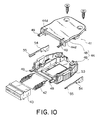
- the connector illustrated in Figs. 8 through 10 is a plug connector 41 to be coupled and connected to a mating connector (which will later be described) in a first direction A1.
- the plug connector 41 comprises a plurality of electroconductive contacts 42, an insulator 43 holding the contacts 42, and a hood 44 covering the insulator 43.
- Each of the contacts 42 is of a butt-contact type and has a part protruding in the first direction A1 from the insulator 43 faced to the mating connector.
- the hood 44 has a principal surface 44a to be faced to the mating connector in the first direction A1.
- the hood 44 is provided with a pair of guide portions 45 protruding from the principal surface 44a in the first direction A1 to guide connection of the plug connector 41 and the mating connector.
- the guide portion 45 has elasticity so as to be elastically bendable in a second direction A2 perpendicular to the first direction A1.
- the hood 44 comprises a pair of hood components 48 butted to each other in the second direction A2 and fixed by a fixture such as a screw.
- Each of the guide portions 45 comprises a combination of a pair of protruding portions 49 integral with the hood components 48, respectively.
- the protruding portions 49 are faced to each other in the second direction A2.
- Each of the protruding portions 49 has elasticity to be elastically bendable in the second direction A2. Between the protruding portions 49, a gap or a slit 51 is left to provide the elasticity.
- the hood 44 has a hood center portion 44b located at the center in a third direction A3 perpendicular to the first and the second directions A1 and A2, and a pair of hood end portions 44c located at opposite ends in the third direction A3. Between the hood center portion 44b and each of the hood end portions 44c, a slit 44d is formed. The guide portion 45 protrudes from each of the hood end portions 44c in the first direction A1.
- the plug connector 41 further comprises a lock mechanism 52 for locking a connected state between the plug connector 41 and the mating connector.
- the lock mechanism 52 comprises an operating portion 53 formed on the hood 44 to be movable in the first direction A1, and a lock spring 54 located between the protruding portions 49 and cooperating with the operating portion 53.
- the lock spring 54 has a locking claw 55 to be engaged with the mating connector in the first direction A1.
- the mating connector is a receptacle connector 61 to be coupled and connected to the plug connector 41 in Figs. 8 through 10 in the first direction A1.
- the receptacle connector 61 comprises an insulator 62 and a plurality of electroconductive mating contacts 63 held between opposite ends 62a and 62b of the insulator 62.
- the insulator 62 is provided with a pair of recessed portions 64 formed at opposite ends 62a and 62b to receive the guide portions 45, respectively. To each of the recessed portions 64, a lock plate 65 is fixed. Each of the lock plates 65 has a locking hole 66 to be engaged with the locking claw 54 of the plug connector 41.
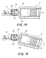
- the recessed portion 64 has an internal dimension H3 slightly smaller than an external dimension H4 of the guide portion 45. Therefore, as illustrated in Fig. 14, no gap is produced between the inner surface of the recessed portion 64 and the outer surface of the guide portion 45 when the plug connector 41 is coupled to the receptacle connector 61. Thus, it is possible to prevent mutual contact between the contacts 42 and the mating contacts 63 from being unstable due to presence of a gap therebetween.
- the guide portion 45 is rich in flexibility. Therefore, as illustrated in Fig. 15, the guide portion 45 is elastically bent if an external force is applied as depicted by a thick white arrow in the figure to cause relative vibration between the plug connector 41 and the receptacle connector 61. It is therefore possible to prevent occurrence of local cracks.
- the receptacle connector 61 is assembled into a terminal apparatus 71 such as a mobile telephone.
- the plug connector 41 is connected to a cord 72.
- the terminal apparatus 71 can be supplied with an electric signal through the plug connector 41 and the receptacle connector 61. Even if external force is applied to the cord 72 in various directions as depicted by thick white arrows in the figure, there is little possibility of causing the above-mentioned problems.
- the plug connector 41 and the receptacle connector 61 are connected to each other and locked by the lock mechanism 52 without operating the operating portion 53.
- the operating portion 53 is operated only when the plug connector 41 is disconnected from the receptacle connector 61.
- the locking claw 55 is engaged with an edge of the locking hole 66 of the lock plate 65 with the lock spring 54 elastically deformed.
- a locked state is achieved.
- the connector comprising the contacts of the butt-contact type is described.
- this invention is also applicable to a connector including a plurality of contacts of a different type.
Landscapes
- Details Of Connecting Devices For Male And Female Coupling (AREA)
- Coupling Device And Connection With Printed Circuit (AREA)
- Connector Housings Or Holding Contact Members (AREA)
Abstract
Description
Claims (10)
- A connector having a principal surface to be faced to an object in a first direction and a guide portion protruding from said principal surface in said first direction for guiding connection of said connector and said object, wherein said guide portion has elasticity so as to be elastically bent in a second direction transverse to said first direction.
- A connector as claimed in claim 1, wherein said guide portion has a slit to provide the elasticity.
- A connector as claimed in claim 1, said connector comprising an electroconductive contact to be contacted to said object, an insulator holding said contact, and a hood covering said insulator, said guide portion being formed as an integral part integral with said hood.
- A connector as claimed in claim 1, wherein said hood has a hood center portion located at the center in a third direction perpendicular to said first and said second directions, and a hood end portion located at an end in said third direction, said guide portion protruding from said hood end portion in said first direction.
- A connector as claimed in claim 4, wherein said hood comprises a pair of hood components butted to each other in said second direction, said guide portion comprising a pair of protruding portions integral with said hood components, respectively, said protruding portions being faced to each other in said second direction, each of said protruding portions having elasticity so as to be elastically bendable in said second direction.
- A connector as claimed in claim 5, further comprising a lock mechanism for locking a connected state between said connector and said object, said lock mechanism having a locking claw located between said protruding portions to be engaged with said object in said first direction.
- A connector as claimed in claim 6, wherein said lock mechanism further comprises a movable operating portion formed on said hood, said locking claw being engaged with and disengaged from said object in cooperation with said operating portion.
- A connector as claimed in claim 5, wherein a gap is left between said protruding portions.
- A mating connector as an object to be connected to and disconnected from a connector claimed in claim 8, said mating connector comprising a mating insulator having a space for receiving said guide portion, said space having an internal dimension smaller than an external dimension of said guide portion.
- A mating connector as claimed in claim 9, said mating connector including a lock plate held by said mating insulator, said lock plate having a locking portion faced to said space to be engaged with said locking claw.
Applications Claiming Priority (2)
| Application Number | Priority Date | Filing Date | Title |
|---|---|---|---|
| JP36281699 | 1999-12-21 | ||
| JP36281699A JP3425690B2 (en) | 1999-12-21 | 1999-12-21 | connector |
Publications (3)
| Publication Number | Publication Date |
|---|---|
| EP1111728A2 true EP1111728A2 (en) | 2001-06-27 |
| EP1111728A3 EP1111728A3 (en) | 2001-12-12 |
| EP1111728B1 EP1111728B1 (en) | 2004-08-25 |
Family
ID=18477804
Family Applications (1)
| Application Number | Title | Priority Date | Filing Date |
|---|---|---|---|
| EP00127483A Expired - Lifetime EP1111728B1 (en) | 1999-12-21 | 2000-12-14 | Connector with an improved guide portion for guiding connection of the connector and an object to be connected thereto |
Country Status (7)
| Country | Link |
|---|---|
| US (1) | US6454592B2 (en) |
| EP (1) | EP1111728B1 (en) |
| JP (1) | JP3425690B2 (en) |
| KR (1) | KR100392135B1 (en) |
| CN (1) | CN1196234C (en) |
| DE (1) | DE60013236T2 (en) |
| TW (1) | TW561650B (en) |
Cited By (6)
| Publication number | Priority date | Publication date | Assignee | Title |
|---|---|---|---|---|
| FR2842036A1 (en) * | 2002-07-08 | 2004-01-09 | Cit Alcatel | ELECTRICAL CONNECTION DEVICE |
| WO2004054043A1 (en) * | 2002-12-12 | 2004-06-24 | Sony Ericsson Mobile Communications Ab | Semi- rigid plug |
| EP1284525A3 (en) * | 2001-08-02 | 2005-03-23 | Hosiden Corporation | Plug type connector |
| EP1524733A1 (en) * | 2003-10-15 | 2005-04-20 | J.S.T. Mfg. Co., Ltd. | Connector |
| WO2005096452A1 (en) * | 2004-03-19 | 2005-10-13 | Molex Incorporated | Electrical connector assembly |
| KR20140035828A (en) * | 2012-09-14 | 2014-03-24 | 타이코 일렉트로닉스 저팬 지.케이. | Connector |
Families Citing this family (35)
| Publication number | Priority date | Publication date | Assignee | Title |
|---|---|---|---|---|
| US6692312B1 (en) * | 1999-11-10 | 2004-02-17 | Ralph Semmeling | Receptacle and plug connectors |
| US6648668B1 (en) * | 2002-07-19 | 2003-11-18 | Hon Hai Precision Ind. Co., Ltd. | Micro coaxial cable connector having latches for securely engaging with a complementary connector |
| USD485240S1 (en) | 2002-08-09 | 2004-01-13 | Japan Aviation Electronics Industry, Limited | Electrical connector |
| DE60310353T2 (en) * | 2002-12-12 | 2007-07-05 | Sony Ericsson Mobile Communications Ab | Semi-rigid connector |
| US7056141B2 (en) * | 2002-12-20 | 2006-06-06 | Atl Technology Lc | Electronic latch interconnect for PDA/cell phone |
| US7627343B2 (en) * | 2003-04-25 | 2009-12-01 | Apple Inc. | Media player system |
| US6776660B1 (en) * | 2003-04-30 | 2004-08-17 | Japan Aviation Electronics Industry, Limited | Connector |
| US6908344B1 (en) * | 2003-12-04 | 2005-06-21 | Dell Products L.P. | System and method for preventing connector damage |
| US7526588B1 (en) | 2004-04-27 | 2009-04-28 | Apple Inc. | Communication between an accessory and a media player using a protocol with multiple lingoes |
| US7826318B2 (en) | 2004-04-27 | 2010-11-02 | Apple Inc. | Method and system for allowing a media player to transfer digital audio to an accessory |
| US7797471B2 (en) | 2004-04-27 | 2010-09-14 | Apple Inc. | Method and system for transferring album artwork between a media player and an accessory |
| US7895378B2 (en) | 2004-04-27 | 2011-02-22 | Apple Inc. | Method and system for allowing a media player to transfer digital audio to an accessory |
| US8117651B2 (en) | 2004-04-27 | 2012-02-14 | Apple Inc. | Method and system for authenticating an accessory |
| US7529871B1 (en) | 2004-04-27 | 2009-05-05 | Apple Inc. | Communication between an accessory and a media player with multiple protocol versions |
| US7673083B2 (en) | 2004-04-27 | 2010-03-02 | Apple Inc. | Method and system for controlling video selection and playback in a portable media player |
| US7441062B2 (en) | 2004-04-27 | 2008-10-21 | Apple Inc. | Connector interface system for enabling data communication with a multi-communication device |
| US7634605B2 (en) * | 2004-04-27 | 2009-12-15 | Apple Inc. | Method and system for transferring stored data between a media player and an accessory |
| US7441058B1 (en) | 2006-09-11 | 2008-10-21 | Apple Inc. | Method and system for controlling an accessory having a tuner |
| US7293122B1 (en) | 2004-04-27 | 2007-11-06 | Apple Inc. | Connector interface system facilitating communication between a media player and accessories |
| US7529870B1 (en) | 2004-04-27 | 2009-05-05 | Apple Inc. | Communication between an accessory and a media player with multiple lingoes |
| US7529872B1 (en) | 2004-04-27 | 2009-05-05 | Apple Inc. | Communication between an accessory and a media player using a protocol with multiple lingoes |
| US7823214B2 (en) | 2005-01-07 | 2010-10-26 | Apple Inc. | Accessory authentication for electronic devices |
| US7525216B2 (en) | 2005-01-07 | 2009-04-28 | Apple Inc. | Portable power source to provide power to an electronic device via an interface |
| US6976876B1 (en) * | 2005-02-18 | 2005-12-20 | Cheng Uei Precision Industry Co., Ltd. | Connector with reduced electromagnetic interference |
| US7632114B2 (en) * | 2006-03-30 | 2009-12-15 | Apple Inc. | Interface connecter between media player and other electronic devices |
| US8006019B2 (en) | 2006-05-22 | 2011-08-23 | Apple, Inc. | Method and system for transferring stored data between a media player and an accessory |
| US7415563B1 (en) | 2006-06-27 | 2008-08-19 | Apple Inc. | Method and system for allowing a media player to determine if it supports the capabilities of an accessory |
| US7558894B1 (en) | 2006-09-11 | 2009-07-07 | Apple Inc. | Method and system for controlling power provided to an accessory |
| US7540788B2 (en) * | 2007-01-05 | 2009-06-02 | Apple Inc. | Backward compatible connector system |
| US8095713B2 (en) * | 2007-09-04 | 2012-01-10 | Apple Inc. | Smart cables |
| USD585028S1 (en) * | 2007-10-09 | 2009-01-20 | Cheng Uei Precision Industry Co., Ltd. | Connector |
| JP5506665B2 (en) * | 2008-04-18 | 2014-05-28 | 株式会社日立メディコ | Magnetic resonance imaging apparatus, receiving coil and manufacturing method thereof |
| US8208853B2 (en) | 2008-09-08 | 2012-06-26 | Apple Inc. | Accessory device authentication |
| US8238811B2 (en) | 2008-09-08 | 2012-08-07 | Apple Inc. | Cross-transport authentication |
| JP7330845B2 (en) * | 2019-10-11 | 2023-08-22 | ヒロセ電機株式会社 | Connector with locking mechanism and connector device |
Family Cites Families (10)
| Publication number | Priority date | Publication date | Assignee | Title |
|---|---|---|---|---|
| US3394337A (en) * | 1966-08-15 | 1968-07-23 | Hughes Aircraft Co | Connector securing device |
| US5316493A (en) * | 1991-08-07 | 1994-05-31 | Bsd Enterprises, Inc. | Electric cord plug fastener and method |
| JP2597289Y2 (en) * | 1993-11-08 | 1999-07-05 | 矢崎総業株式会社 | Connector housing with locking mechanism |
| US5387110A (en) * | 1993-11-12 | 1995-02-07 | International Business Machines Corporation | Reversible dual media adapter cable |
| US5411402A (en) * | 1993-12-17 | 1995-05-02 | Itt Corporation | Connector assembly for IC card |
| FR2715004B1 (en) * | 1994-01-13 | 1996-03-01 | Radiall Sa | Microminiature coaxial connector with snap lock. |
| US5538437A (en) * | 1995-03-03 | 1996-07-23 | Itt Industries, Inc. | Connector assembly for IC card |
| US5830001A (en) * | 1995-03-31 | 1998-11-03 | Japan Aviation Electronics Industry, Limited | Connector capable of reliably locking a plug connector to a receptacle connector |
| US5683264A (en) * | 1995-11-01 | 1997-11-04 | International Business Machines Corporation | PCMCI cable connector with latching indicator |
| DE19753521C2 (en) * | 1997-12-03 | 2000-04-06 | Amphenol Tuchel Elect | Connectors |
-
1999
- 1999-12-21 JP JP36281699A patent/JP3425690B2/en not_active Expired - Fee Related
-
2000
- 2000-12-14 DE DE60013236T patent/DE60013236T2/en not_active Expired - Fee Related
- 2000-12-14 EP EP00127483A patent/EP1111728B1/en not_active Expired - Lifetime
- 2000-12-15 US US09/738,442 patent/US6454592B2/en not_active Expired - Lifetime
- 2000-12-19 CN CNB001357441A patent/CN1196234C/en not_active Expired - Fee Related
- 2000-12-20 TW TW089127357A patent/TW561650B/en not_active IP Right Cessation
- 2000-12-21 KR KR10-2000-0079686A patent/KR100392135B1/en not_active Expired - Fee Related
Cited By (12)
| Publication number | Priority date | Publication date | Assignee | Title |
|---|---|---|---|---|
| EP1284525A3 (en) * | 2001-08-02 | 2005-03-23 | Hosiden Corporation | Plug type connector |
| FR2842036A1 (en) * | 2002-07-08 | 2004-01-09 | Cit Alcatel | ELECTRICAL CONNECTION DEVICE |
| EP1381119A1 (en) * | 2002-07-08 | 2004-01-14 | Alcatel | Electrical connecting device |
| WO2004054043A1 (en) * | 2002-12-12 | 2004-06-24 | Sony Ericsson Mobile Communications Ab | Semi- rigid plug |
| KR100746451B1 (en) * | 2002-12-12 | 2007-08-03 | 소니 에릭슨 모빌 커뮤니케이션즈 에이비 | Connector and plug for insertion into a socket |
| EP1524733A1 (en) * | 2003-10-15 | 2005-04-20 | J.S.T. Mfg. Co., Ltd. | Connector |
| US7040904B2 (en) | 2003-10-15 | 2006-05-09 | J.S.T. Mfg. Co., Ltd. | Connector |
| WO2005096452A1 (en) * | 2004-03-19 | 2005-10-13 | Molex Incorporated | Electrical connector assembly |
| CN100492778C (en) * | 2004-03-19 | 2009-05-27 | 莫列斯公司 | Electrical connector assembly |
| KR20140035828A (en) * | 2012-09-14 | 2014-03-24 | 타이코 일렉트로닉스 저팬 지.케이. | Connector |
| EP2709216A3 (en) * | 2012-09-14 | 2014-10-22 | Tyco Electronics Japan G.K. | Connector |
| US9118142B2 (en) | 2012-09-14 | 2015-08-25 | Tyco Electronics Japan G.K. | Connector having a lock with a locking protrusion actuated by a slide member |
Also Published As
| Publication number | Publication date |
|---|---|
| KR20010062582A (en) | 2001-07-07 |
| DE60013236D1 (en) | 2004-09-30 |
| DE60013236T2 (en) | 2005-08-11 |
| JP3425690B2 (en) | 2003-07-14 |
| JP2001176620A (en) | 2001-06-29 |
| US20010004564A1 (en) | 2001-06-21 |
| CN1196234C (en) | 2005-04-06 |
| KR100392135B1 (en) | 2003-07-23 |
| TW561650B (en) | 2003-11-11 |
| EP1111728A3 (en) | 2001-12-12 |
| US6454592B2 (en) | 2002-09-24 |
| CN1301065A (en) | 2001-06-27 |
| EP1111728B1 (en) | 2004-08-25 |
Similar Documents
| Publication | Publication Date | Title |
|---|---|---|
| US6454592B2 (en) | Connector with an improved guide portion for guiding connection the connector and an object to be connected thereto | |
| US6935893B1 (en) | Electrical connector with terminal position assurance device | |
| KR100433704B1 (en) | Connector excellent in reliability of contact | |
| US7134912B2 (en) | Electrical connector having a shell with a portion which is elastically movable in a fitting portion of the connector | |
| US6168445B1 (en) | Two-part electrical connector | |
| US5252084A (en) | Lever type connector | |
| JP3351999B2 (en) | Electrical connector | |
| US10886640B2 (en) | Conductive terminal and electrical connector | |
| US6676433B1 (en) | Connector | |
| US5716230A (en) | Surface engageable electrical connector | |
| KR940002222Y1 (en) | Power socket | |
| JPH10334993A (en) | Connector device | |
| US7278876B2 (en) | Connector in which two housings holding a cable are firmly engaged with each other | |
| CN212542840U (en) | Plug connector and connector assembly | |
| JP3467419B2 (en) | Connector lock structure | |
| US12494600B2 (en) | Terminal and a connector | |
| JPH11250985A (en) | Connector mating structure | |
| US20050090140A1 (en) | Connector assuring more reliable connection of a cable | |
| US8668508B2 (en) | Connector | |
| US6302722B1 (en) | Mating/unmating system for electrical connectors | |
| JP2627137B2 (en) | connector | |
| CN120834458A (en) | Electrical connection device | |
| CN223911988U (en) | Fastening device | |
| JP3788959B2 (en) | Connector mounting structure and connector device | |
| EP4583323A1 (en) | Connector assembly and method of assembling a connector assembly |
Legal Events
| Date | Code | Title | Description |
|---|---|---|---|
| PUAI | Public reference made under article 153(3) epc to a published international application that has entered the european phase |
Free format text: ORIGINAL CODE: 0009012 |
|
| AK | Designated contracting states |
Kind code of ref document: A2 Designated state(s): AT BE CH CY DE DK ES FI FR GB GR IE IT LI LU MC NL PT SE TR Kind code of ref document: A2 Designated state(s): DE FI FR GB SE |
|
| AX | Request for extension of the european patent |
Free format text: AL;LT;LV;MK;RO;SI |
|
| PUAL | Search report despatched |
Free format text: ORIGINAL CODE: 0009013 |
|
| AK | Designated contracting states |
Kind code of ref document: A3 Designated state(s): AT BE CH CY DE DK ES FI FR GB GR IE IT LI LU MC NL PT SE TR |
|
| AX | Request for extension of the european patent |
Free format text: AL;LT;LV;MK;RO;SI |
|
| RIC1 | Information provided on ipc code assigned before grant |
Free format text: 7H 01R 13/62 A, 7H 01R 13/629 B |
|
| 17P | Request for examination filed |
Effective date: 20020604 |
|
| AKX | Designation fees paid |
Free format text: DE FI FR GB SE |
|
| 17Q | First examination report despatched |
Effective date: 20030724 |
|
| GRAP | Despatch of communication of intention to grant a patent |
Free format text: ORIGINAL CODE: EPIDOSNIGR1 |
|
| GRAS | Grant fee paid |
Free format text: ORIGINAL CODE: EPIDOSNIGR3 |
|
| GRAA | (expected) grant |
Free format text: ORIGINAL CODE: 0009210 |
|
| RIN1 | Information on inventor provided before grant (corrected) |
Inventor name: TAKAGI, OSAMU,JAPAN AVIATION ELECTRONICS IND. LTD |
|
| AK | Designated contracting states |
Kind code of ref document: B1 Designated state(s): DE FI FR GB SE |
|
| REG | Reference to a national code |
Ref country code: GB Ref legal event code: FG4D |
|
| REG | Reference to a national code |
Ref country code: IE Ref legal event code: FG4D |
|
| REF | Corresponds to: |
Ref document number: 60013236 Country of ref document: DE Date of ref document: 20040930 Kind code of ref document: P |
|
| REG | Reference to a national code |
Ref country code: SE Ref legal event code: TRGR |
|
| ET | Fr: translation filed | ||
| PLBE | No opposition filed within time limit |
Free format text: ORIGINAL CODE: 0009261 |
|
| STAA | Information on the status of an ep patent application or granted ep patent |
Free format text: STATUS: NO OPPOSITION FILED WITHIN TIME LIMIT |
|
| 26N | No opposition filed |
Effective date: 20050526 |
|
| PGFP | Annual fee paid to national office [announced via postgrant information from national office to epo] |
Ref country code: FI Payment date: 20071217 Year of fee payment: 8 |
|
| PGFP | Annual fee paid to national office [announced via postgrant information from national office to epo] |
Ref country code: SE Payment date: 20071212 Year of fee payment: 8 |
|
| PGFP | Annual fee paid to national office [announced via postgrant information from national office to epo] |
Ref country code: GB Payment date: 20071217 Year of fee payment: 8 |
|
| PGFP | Annual fee paid to national office [announced via postgrant information from national office to epo] |
Ref country code: DE Payment date: 20071228 Year of fee payment: 8 |
|
| PGFP | Annual fee paid to national office [announced via postgrant information from national office to epo] |
Ref country code: FR Payment date: 20071227 Year of fee payment: 8 |
|
| PG25 | Lapsed in a contracting state [announced via postgrant information from national office to epo] |
Ref country code: FI Free format text: LAPSE BECAUSE OF NON-PAYMENT OF DUE FEES Effective date: 20081214 |
|
| EUG | Se: european patent has lapsed | ||
| GBPC | Gb: european patent ceased through non-payment of renewal fee |
Effective date: 20081214 |
|
| REG | Reference to a national code |
Ref country code: FR Ref legal event code: ST Effective date: 20090831 |
|
| PG25 | Lapsed in a contracting state [announced via postgrant information from national office to epo] |
Ref country code: DE Free format text: LAPSE BECAUSE OF NON-PAYMENT OF DUE FEES Effective date: 20090701 |
|
| PG25 | Lapsed in a contracting state [announced via postgrant information from national office to epo] |
Ref country code: GB Free format text: LAPSE BECAUSE OF NON-PAYMENT OF DUE FEES Effective date: 20081214 |
|
| PG25 | Lapsed in a contracting state [announced via postgrant information from national office to epo] |
Ref country code: FR Free format text: LAPSE BECAUSE OF NON-PAYMENT OF DUE FEES Effective date: 20081231 |
|
| PG25 | Lapsed in a contracting state [announced via postgrant information from national office to epo] |
Ref country code: SE Free format text: LAPSE BECAUSE OF NON-PAYMENT OF DUE FEES Effective date: 20081215 |