EP1111726A2 - Connector contact and method of manufacturing the same - Google Patents
Connector contact and method of manufacturing the same Download PDFInfo
- Publication number
- EP1111726A2 EP1111726A2 EP00127726A EP00127726A EP1111726A2 EP 1111726 A2 EP1111726 A2 EP 1111726A2 EP 00127726 A EP00127726 A EP 00127726A EP 00127726 A EP00127726 A EP 00127726A EP 1111726 A2 EP1111726 A2 EP 1111726A2
- Authority
- EP
- European Patent Office
- Prior art keywords
- contact
- elastic pieces
- pair
- portions
- main body
- Prior art date
- Legal status (The legal status is an assumption and is not a legal conclusion. Google has not performed a legal analysis and makes no representation as to the accuracy of the status listed.)
- Withdrawn
Links
Images



Classifications
-
- H—ELECTRICITY
- H01—ELECTRIC ELEMENTS
- H01R—ELECTRICALLY-CONDUCTIVE CONNECTIONS; STRUCTURAL ASSOCIATIONS OF A PLURALITY OF MUTUALLY-INSULATED ELECTRICAL CONNECTING ELEMENTS; COUPLING DEVICES; CURRENT COLLECTORS
- H01R13/00—Details of coupling devices of the kinds covered by groups H01R12/70 or H01R24/00 - H01R33/00
- H01R13/02—Contact members
- H01R13/10—Sockets for co-operation with pins or blades
- H01R13/11—Resilient sockets
- H01R13/112—Resilient sockets forked sockets having two legs
-
- H—ELECTRICITY
- H01—ELECTRIC ELEMENTS
- H01R—ELECTRICALLY-CONDUCTIVE CONNECTIONS; STRUCTURAL ASSOCIATIONS OF A PLURALITY OF MUTUALLY-INSULATED ELECTRICAL CONNECTING ELEMENTS; COUPLING DEVICES; CURRENT COLLECTORS
- H01R43/00—Apparatus or processes specially adapted for manufacturing, assembling, maintaining, or repairing of line connectors or current collectors or for joining electric conductors
- H01R43/16—Apparatus or processes specially adapted for manufacturing, assembling, maintaining, or repairing of line connectors or current collectors or for joining electric conductors for manufacturing contact members, e.g. by punching and by bending
Definitions
- the present invention relates to a connector contact capable of coping with a decrease in pitch and shortening the time required for assembly.
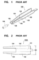
- a so-called tulip-shaped contact 100 with the structure shown in Fig. 1 is available.
- the contact 100 is comprised of a main body portion 103 bent to have a U-shaped section and having a base plate portion 101 and a pair of parallel upright plate portions 102 standing vertically from the two edges of the base plate portion 101, elastic pieces 104 extending like beams in the same direction from the respective upright plate portions 102 of the main body portion 103, and contact portions 105 formed at the distal ends of the elastic pieces 104.
- the elastic pieces 104 elastically deform, as they are forced apart by the male contact 106, to separate the contact portions 105 apart from each other so as to receive the inserted male contact 106 between them. Simultaneously, the contact portions 105 are urged against the male contact 106 by the elastic forces of the elastic pieces 104, so that they come into reliable contact with the male contact 106.
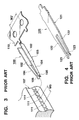
- a connector is to be fabricated by building this contact 100 into a connector housing 107 shown in Fig. 3.
- a flat plate member is punched to form a flat plate-like blank in which a plurality of contact forming portions 100A each shown in Fig. 2 are lined at the equal pitch in a common carrier 110 shown in Fig. 3.
- the contact portions 105 are formed at the elastic pieces 104 of each contact forming portion 100A of this blank so as to make the elastic pieces 104 serve as contacts, and after that the contact forming portion 100A is bent at bending lines indicated by alternate long and short dashed lines in Fig. 2 to have the shape of the contact 100.
- the plurality of contacts 100 held by the carrier 110 in this manner are inserted in holes 111 in the connector housing 107 simultaneously, and then the individual contacts 100 are separated by cutting.
- a pitch W0 shown in Fig. 3 with which the contacts 100 are disposed in the connector is greatly narrowed.
- the mainstream pitch W0 is 2.0 mm, and a connector with a pitch of about 1.5 mm is also under development.
- the pitch with which the contact forming portions 100A, serving as a developing form of the contacts 100, are to be disposed must also be narrowed.
- the contact 100 with the shape described above, after the male contact 106 is fitted in it, it clamps the male contact 106 with contact forces, thereby exhibiting its connecting function.
- the main body portion 103 that supports the proximal portions of the elastic pieces 104 so that they oppose each other must be bent into a U-shape, and the U-shaped main body portion 103 must have such a size that it can sufficiently receive the male contact 106 (more specifically, when the male contact has a width of 0.5 mm, the main body portion 103 must have an inner width of about 1.5 mm). Consequently, the width W2 described above increases undesirably.
- a so-called fork-shaped contact 120 with the structure shown in Fig. 4 is available.
- This contact 120 has a flat plate-like shape as a whole, and is comprised of a main body portion 121, a pair of elastic pieces 122 extending like beams from the two sides of the main body portion 121, and contact portions 123 respectively formed at the distal ends of the elastic pieces 122.
- the elastic pieces 122 elastically deform, as they are forced apart by the male contact, to separate the contact portions 123 apart from each other so as to receive the inserted male contact between them.
- the contact portions 123 are urged against the male contact by the elastic forces of the elastic pieces 122, so that they come into contact with the male contact.
- a connector is to be fabricated by building this contact 120 in a connector housing.
- a flat plate member is punched to form a flat plate-like blank in which a plurality of contacts 120 each with the shape described above are lined at the equal pitch, and after that the plurality of contacts 120 are inserted in the holes in the connector housing simultaneously.
- the contacts 120 since the main body portions 121 need not be formed to have a U-shaped section like that of the main body portion 103, the width of the contact 120 can be decreased, and accordingly the pitch with which the contacts are disposed in the blank can also be decreased. Even when coping with a decrease in pitch with which the contacts are to be disposed, the contacts 120 can be inserted in the adjacent holes of the connector housing simultaneously with one blank. As a result, the time required for assembly can be shortened, and the amount of material necessary for forming each contact 120 decreases, leading to a decrease in cost.
- the male contact cannot have a sufficiently large insertion length due to the problem of interference with the main body portion 121, and the male contact can be sometimes disengaged easily during use.
- Japanese Unexamined Patent Publication No. 7-326417 discloses a contact that can solve the problem on contact error of the contact 120 described above.
- This contact is a fork-shaped contact comprised of a main body portion, a pair of elastic pieces extending like beams in the same direction from two sides of the main body portion, and contact portions respectively formed at the distal ends of the elastic pieces.
- the elastic pieces are twisted midway, so those portions of the contact portions which come into contact with a male contact form high-smoothness rolled surfaces.
- the male contact cannot have a sufficiently large insertion length due to the problem of interference with the main body portion, and the male contact can be sometimes disengaged easily during use.
- the present invention has been made in view of the above situations in the prior art, and has as its object to provide connector contact which can cope with a decrease in pitch, shorten the time required for assembly, decrease the cost, come into contact with a male contact with high-smoothness rolled surfaces, and assure a sufficiently large insertion length of the male contact.
- a connector contact having a main body portion, a pair of elastic pieces extending like beams on the same side from two sides of the main body portion, and contact portions respectively formed in distal ends of the elastic pieces, to come into contact with a male contact inserted between the contact portions, wherein the pair of elastic pieces have, at the distal ends thereof, protrusions at which the contact portions are to be arranged and each of which projects in a lateral direction opposite to the other elastic piece, and the pair of elastic pieces are deformed by twisting or bending, so that the contact portions oppose each other.
- the pair of elastic pieces extending like beams on the same side from two sides of the main body portion have, at their distal ends, the protrusions at which the contact portions are to be arranged and each of which projects in the lateral direction opposite to the other elastic piece, and the pair of elastic pieces are deformed by twisting or bending, so that the contact portions arranged on the protrusions oppose each other. Therefore, the main body portion need not be formed to have a C-shaped section, and the width of the contact can be decreased.
- the pair of elastic pieces are deformed by twisting or bending, so that their contact portions oppose each other. Accordingly, those portions of the contact portions with which the contact portions come into contact with the male contact can form high-smoothness rolled surfaces. Hence, the contact portions can come into contact with the male contact with the high-smoothness rolled surfaces.
- the pair of elastic pieces have, at their respective distal ends, the protrusions at which the contact portions are to be arranged and each of which projects in the lateral direction opposite to the other elastic piece, and the pair of elastic pieces are deformed by twisting or bending, so that the contact portions oppose each other. Accordingly, the contact portions can be arranged at positions shifted from that of the main body portion. Hence, the male contact can have a sufficiently large insertion length.
- the pair of elastic pieces are deformed by bending, so that the contact portions oppose each other.
- the pair of elastic pieces are deformed by bending, so that the contact portions oppose each other. Therefore, when compared to a case wherein the contact portions are made to oppose each other by deforming the pair of elastic pieces by twisting, the number of steps can be decreased, and the contact portions can have high precision.
- the pair of elastic pieces are deformed by bending at linear portions extending in the protrusions along an inserting direction of the male contact, so that the contact portions oppose each other.
- the pair of elastic pieces are deformed by bending at the linear portions extending in the protrusions along the inserting direction of the male contact, so that the contact portions oppose each other. Therefore, the punch and die of the press can have simple shapes. Accordingly, the manufacturing cost can be reduced.
- each of the pair of elastic pieces is deformed by bending at a first linear portion arranged closer than the protrusion of one elastic piece to the other elastic piece, and a second linear portion extending obliquely from the first linear portion on a side closer to the main body portion to an outer end of the elastic piece, so that the contact portions oppose each other.
- each of the pair of elastic pieces is deformed by bending at the first linear portion arranged closer than the protrusion of one elastic piece to the other elastic piece, and the second linear portion extending obliquely from the first linear portion on the side closer to the main body portion to the outer end of the elastic piece, so that the contact portions oppose each other. Therefore, slant portions can be formed at the proximal portions of the protrusions closer to the main body portion. The slant portions can accordingly prevent stress concentration at the proximal portions of the protrusions and can improve the strength.
- the contact portions can be separated apart from each other without changing their postures, and consequently they can come into good contact with the male contact.
- each of the elastic pieces is bent at the first linear portion arranged inner than its protrusion to extend along the inserting direction of the male contact, the distance between the two protrusions before bending can be further decreased while assuring the heights of the protrusions after bending. This can cope with a further decrease in contact pitch.
- the protrusions on the sides closer to the main body portion have slant portions which slant such that the closer to the main body portion, the smaller their projecting amounts.
- the protrusions on the sides closer to the main body portion have the slant portions which slant such that the closer to the main body portion, the smaller their projecting amounts.
- these slant portions can prevent stress concentration at the proximal portions of the protrusions and can improve the strength.
- the contact portions can be separated apart from each other without changing their postures, and consequently they can come into good contact with the male contact.
- a method of manufacturing a connector contact which has a main body portion and a pair of elastic pieces extending like beams on the same side from two sides of the main body portion, and in which distal ends of the pair of elastic pieces have protrusions at which contact portions are to be arranged and each of which projects in a lateral direction opposite to the other elastic piece, the contact portions being made to oppose each other by deforming the pair of elastic pieces by bending, comprising the steps of deforming the distal ends of the main body portion, at which the pair of elastic pieces are to be formed, by bending so that the contact portions oppose each other, and punching an intermediate portion of the distal end of the main body portion in a longitudinal direction into a predetermined length to separately form the pair of elastic pieces.
- a connector contact (to be simply referred to as a contact hereinafter) 10 is a female contact to fit on a rectangular prismatic male contact 11 with a tapered distal end, as shown in Fig. 5, and has a main body portion 12, a pair of elastic pieces 13 extending like beams on the same side from the two sides of the main body portion 12, and contact portions 14 respectively formed at the distal ends of the elastic pieces 13.
- the contact 10 is elongated and flat as a whole, and is specular-symmetrical about the center line along the longitudinal direction.
- the contact 10 is formed by plating phosphor bronze by gilt finish with an underlying nickel layer, and has a thickness of about 0.2 mm.
- the male contact 11 is linearly inserted in the contact 10 parallel to the longitudinal direction of the contact 10.
- the main body portion 12 is an elongated flat plate as a whole, and projections 16 projecting outward in the widthwise direction are formed on the two sides in the widthwise direction of the main body portion 12.
- the pair of elastic pieces 13 extend from the two sides in the widthwise direction at one end in the longitudinal direction of the main body portion 12 to separate from each other along the longitudinal direction of the main body portion 12, and their extending distal ends are slightly slanted to come close to each other.
- Those portions of the pair of elastic pieces 13 which are to be integrally connected to the main body portion 12 are arcuatedly chamfered (so-called curvature chamfering).
- Projections 17 are formed on the opposing sides of the respective distal ends of the pair of elastic pieces 13 to project so as to come close to each other, such that their opposing surfaces are parallel to each other.
- the pair of elastic pieces 13 have flat portions 18 which form the same plane as the main body portion 12 on most of their main body portion 12 sides.
- Upright portions 20 are formed on the outer sides in the widthwise direction of the respective distal ends of the pair of elastic pieces 13 to stand upright substantially vertically from the flat portions 18 so they have opposing surfaces.
- the upright portions 20 of the pair of elastic pieces 13 are formed roughly in the following manner.
- Each of the pair of elastic pieces 13 is deformed by bending at a corresponding bending line 26 comprised of a first linear portion 26a arranged on a side closer than the boundary line X between it and its protrusion 23 to the other elastic piece 13 and parallel to the longitudinal direction (i.e., the inserting direction of the male contact 11) of the contact 10, a second linear portion 26b extending obliquely from the corresponding first linear portion 26a on the main body portion 12 side to the neighboring outer end of the elastic piece proximal portion 22 closer to the main body portion 12 than the protrusion 23, and a curved portion 26c that arcuatedly connects the corresponding first and second linear portions 26a and 26b to each other, thereby forming the upright portion 20 described above.
- the first linear portions 26a of the pair of elastic pieces 13 are parallel to each other, as a matter of course.
- Each of the upright portions 20 formed in the above manner is constituted by the protrusion 23 and a connecting portion 27 formed closer to the protrusion 23 than the bending line 26 of the elastic piece 13.
- that portion of the elastic piece 13 from which the connecting portion 27 is excluded, that is, the portion closer to the main body portion 12 than the bending line 26 forms the flat portion 18.
- each of the connecting portions 27 forms a slant portion 28 at its portion as the proximal portion of the protrusion 23 closer to the main body portion 12 to obliquely connect the protrusion 23 and flat portion 18 to each other. More specifically, the slant portions 28 are slanted such that the closer to the protrusions 23, the higher they are above the flat portions 18, and the closer to the main body portion 12, the lower they are above the flat portions 18.
- the slant portions 28 are slanted such that the closer to the protrusions 23 with a slant larger than the slant based on the slant of the elastic pieces 13 where they are arranged, the more inner they are, and the closer to the main body portion 12, the more outer they are.
- Each of the upright portions 20 has, at its protrusion 23, the contact portion 14 which extends opposite to the main body portion 12 to form a rectangular shape and which is bent such that its intermediate portion in the extending direction is bent toward the other elastic piece 13 while forming a V shape when seen from a direction perpendicular to the main body portion 12. Consequently, the contact portions 14 are formed to oppose each other at the respective distal ends of the pair of elastic pieces 13.
- a flat plate member is punched by outer shape punching with a press to form a flat plate-like blank 31 in which a plurality of contact forming portions 10A are aligned and connected to a carrier 30 at their proximal end sides (a side opposite to the protrusions 23), as shown in Fig. 7.
- each contact forming portion 10A naturally has a planar shape as a developing form of the contact 10 before bending.
- a portion between the pair of elastic pieces 13 is not punched out and the elastic pieces 13 are not accordingly separated from each other.
- the contact forming portion 10A has a main body portion 12, an elastic piece forming portion 13A in which a pair of elastic piece proximal portions 22 are connected to each other at their inner sides throughout their entire lengths, and a pair of protrusions 23 projecting outward from two sides in a lateral direction of the elastic piece forming portion 13A opposite to the main body portion 12.
- a punch 34 with edges 33 formed on its two sides to have shapes matching the bending lines 26, and a die 36 with a recess 35 that can receive the punch 34 with a gap corresponding to the thickness of the contact 10 are used, and the contact forming portion 10A is pressed by pushing it into the recess 35 of the die 36 with the punch 34.
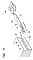
- the pair of elastic pieces 13 as the elastic piece forming portion 13A before separation are bent to form the upright portions 20, so the contact portions 14 oppose each other. Then, a portion between the prospective pair of elastic pieces 13 is punched out by the press, to form the pair of elastic pieces 13 separately, as shown in Fig. 11. Thus, the contact forming portion 10A becomes the contact 10.
- the plurality of contacts 10 that are lined and connected to each other through the carrier 30 are inserted in a plurality of adjacent holes 39 of a connector housing 38 simultaneously, and after that the individual contacts 10 are separated by cutting.
- the male contact 11 In connecting connectors to each other, when the male contact 11 is connected to the corresponding contact 10, it enters between the contact portions 14 of the contact 10. Then, the pair of elastic pieces 13 are pushed by the male contact 11 and are elastically deformed in directions to separate from each other, so that the contact portions 14 are separated apart from each other, without changing their postures, at such a width that the male contact 11 can be inserted between them.
- the male contact 11 When the male contact 11 is inserted between the contact portions 14, they are both urged against the male contact 11 by the elastic forces of the elastic pieces 13 on the two sides, and come into good contact with the male contact 11, so that they are electrically connected to it. Since the heights of the contact portions 14 are naturally different from that of the main body portion 12, the male contact 11 can be inserted deep without being interfered by the main body portion 12.
- the respective distal ends of the pair of elastic pieces 13 extending like beams on the same side from the two sides of the main body portion 12 have protrusions 23 at which the contact portions 14 are to be arranged and each of which projects in the lateral direction opposite to the other elastic piece 13.
- the pair of elastic pieces 13 are deformed by bending so that the contact portions 14 formed on the respective protrusions 23 oppose each other. Therefore, the main body portion 12 need not be formed to have a U-shaped section, and a width W1 of the contact forming portion 10A in a developed form can be narrowed, as shown in Fig. 7. As a result, a contact pitch W1' in the blank can also be decreased (note that W1' ⁇ W1).
- the pair of elastic pieces 13 are deformed by bending, so that their contact portions 14 oppose each other. Accordingly, those surfaces of the contact portions 14 with which the contact portions 14 come into contact with the male contact 11 can form high-smoothness rolled surfaces. Hence, the contact portions 14 can come into contact with the male contact 11 with the high-smoothness rolled surfaces.
- the respective distal ends of the pair of elastic pieces 13 have protrusions 23 at which the contact portions 14 are to be arranged and each of which projects in the lateral direction opposite to the other elastic piece 13, and the pair of elastic pieces 13 are deformed by bending, so that the contact portions 14 formed on the respective protrusions 23 oppose each other. Accordingly, the contact portions 14 can be arranged at positions (heights) shifted from that of the main body portion 12. Hence, the male contact 11 can have a sufficiently large insertion length.
- each of the pair of elastic pieces 13 is deformed by bending at the corresponding bending line 26 comprised of the first linear portion 26a arranged on a side closer to the other elastic piece 13 than the corresponding protrusion 23, the second linear portion 26b extending obliquely from the corresponding first linear portion 26a on the main body portion 12 side to the outer end of the elastic piece 13 where it is arranged, and the curved portion 26c that arcuatedly connects to each other the corresponding first and second linear portions 26a and 26b that are arranged on the same elastic piece 13.
- the slant portions 28 can accordingly be formed on the proximal portions of the protrusions 23 closer to the main body portion 12.
- the slant portions 28 can prevent stress concentration at the proximal portions of the protrusions 23 and can increase the strength.
- the contact portions 14 can be separated apart from each other without changing their postures, and consequently they can come into good contact with the male contact 11.
- each of the elastic pieces 13 is bent at the first linear portion 26a arranged more inner than its protrusion 23, the distance between the two protrusions 23 before bending can be further decreased while assuring the heights of the protrusions 23 after bending. This can cope with a further decrease in contact pitch.
- the pair of elastic pieces 13 are bent in the form of the elastic piece forming portion 13A before separation, so the contact portions 14 oppose each other. After that, that portion in the elastic piece forming portion 13A which forms the pair of elastic pieces 13 is punched, thereby separately forming the elastic pieces 13.
- the contact 10 when performing bending, the contact 10 can be stably pressed at its wide continuous elastic piece forming portion 13A comprised of the pair of elastic pieces 13 and the portion between them. Therefore, the bending precision can be greatly improved.
- the upright portions 20 are obtained by bending the pair of elastic pieces 13 so that the contact portions 14 oppose each other.
- elastic pieces 13 may be deformed by twisting, as shown in Fig. 12. In Fig. 12, a portion between protrusions 23 of the elastic pieces 13 and a main body portion 12 is twisted.
- the embodiment described above, in which the contact portions 14 are made to oppose each other by bending the pair of elastic pieces 13, is preferable since the number of steps can be decreased. More specifically, in order to make the contact portions 14 to oppose each other by twisting the elastic pieces 13 with a press, at least two steps of bending each at 45° are necessary. If deformation is performed by bending with the press as in the above embodiment, it can be done in one step.
- Bending deformation is preferable because it can assure good precision of the two contact portions 14. More specifically, 50 pieces of contacts in each of which the contact portions 14 are made to oppose each other by twisting the elastic pieces 13, and 50 pieces of contact in each of which the contact portions 14 are made to oppose each other by bending the elastic pieces 13, were manufactured on the trial basis under the same manufacturing conditions, and the distances between the contact portions 14 of the resultant contacts were measured. Table 1 shows the results. Twisting Deformation Bending Deformation Average Value (mm) 0.205 0.208 Maximum Value (mm) 0.228 0.219 Minimum Value (mm) 0.182 0.189 Standard Deviation 0.0104 0.0022
- contact portions 14 may be made to oppose each other by bending a pair of elastic pieces 13 of a contact 10 at linear portions 41 arranged in respective protrusions 23 and parallel to the inserting direction of a male contact 11 (see Fig. 5).
- the punch and die of the press can be made with simple shapes, so that the manufacturing cost can be decreased.
- slant portions 44 may be formed on protrusions 23 on sides closer to a main body portion 12, to slant such that the closer to the main body portion 12, the smaller the protruding amount.
- stress concentration on the proximal portions of the protrusions 23 can be reliably prevented by the slant portions 44, thereby reliably increasing the strength.
- the slant portions 44 ones with slant surfaces 43 which are continuous to the distal end faces of the protruding sides of the protrusions 23, as shown in Fig. 14, are the most preferable from the viewpoint of improving the strength of the protrusions 23.
Landscapes
- Engineering & Computer Science (AREA)
- Manufacturing & Machinery (AREA)
- Coupling Device And Connection With Printed Circuit (AREA)
- Manufacturing Of Electrical Connectors (AREA)
Abstract
Description
| Twisting Deformation | Bending Deformation | |
| Average Value (mm) | 0.205 | 0.208 |
| Maximum Value (mm) | 0.228 | 0.219 |
| Minimum Value (mm) | 0.182 | 0.189 |
| Standard Deviation | 0.0104 | 0.0022 |
Claims (6)
- A connector contact having a main body portion, a pair of elastic pieces extending like beams on the same side from two sides of said main body portion, and contact portions respectively formed at distal ends of said elastic pieces, to come into contact with a male contact inserted between said contact portions, wherein
said pair of elastic pieces have, at said distal ends thereof, protrusions at which said contact portions are to be arranged and each of which projects in a lateral direction opposite to the other elastic piece, and said pair of elastic pieces are deformed by twisting or bending, so that said contact portions oppose each other. - A connector contact according to claim 1, wherein said pair of elastic pieces are deformed by bending, so that said contact portions oppose each other.
- A connector contact according to claim 2, wherein said pair of elastic pieces are deformed by bending at linear portions extending in said protrusions along an inserting direction of said male contact, so that said contact portions oppose each other.
- A connector contact according to claim 2, wherein each of said pair of elastic pieces is deformed by bending at a first linear portion arranged closer than said protrusion of one elastic piece to the other elastic piece, and a second linear portion extending obliquely from said first linear portion on a side closer to said main body portion to an outer end of said elastic piece, so that said contact portions oppose each other.
- A connector contact according to any one of claims 1 to 4, wherein said protrusions on said sides closer to said main body portion have slant portions which slant such that the closer to said main body portion, the smaller projecting amounts thereof.
- A method of manufacturing a connector contact which has a main body portion and a pair of elastic pieces extending like beams on the same side from two sides of said main body portion, and in which said pair of elastic pieces have, at distal ends thereof, protrusions at which contact portions are to be arranged and each of which projects in a lateral direction opposite to the other elastic piece, said contact portions being made to oppose each other by deforming so that said contact portions oppose each other, comprising:
deforming said pair of elastic pieces in a state before being separated from each other by bending so that said contact portions oppose each other; and after that punching a portion between said pair of elastic piece, thereby separately forming said pair of elastic pieces.
Applications Claiming Priority (2)
| Application Number | Priority Date | Filing Date | Title |
|---|---|---|---|
| JP36190399 | 1999-12-20 | ||
| JP36190399A JP3344981B2 (en) | 1999-12-20 | 1999-12-20 | Connector contact and method of manufacturing the same |
Publications (2)
| Publication Number | Publication Date |
|---|---|
| EP1111726A2 true EP1111726A2 (en) | 2001-06-27 |
| EP1111726A3 EP1111726A3 (en) | 2004-12-22 |
Family
ID=18475241
Family Applications (1)
| Application Number | Title | Priority Date | Filing Date |
|---|---|---|---|
| EP00127726A Withdrawn EP1111726A3 (en) | 1999-12-20 | 2000-12-18 | Connector contact and method of manufacturing the same |
Country Status (6)
| Country | Link |
|---|---|
| US (1) | US6554659B2 (en) |
| EP (1) | EP1111726A3 (en) |
| JP (1) | JP3344981B2 (en) |
| CN (1) | CN1156945C (en) |
| CA (1) | CA2328658C (en) |
| TW (1) | TW483193B (en) |
Cited By (1)
| Publication number | Priority date | Publication date | Assignee | Title |
|---|---|---|---|---|
| EP2766956A4 (en) * | 2011-10-14 | 2015-05-20 | Delphi Tech Inc | Tuning fork electrical contact with prongs having non-rectangular shape |
Families Citing this family (16)
| Publication number | Priority date | Publication date | Assignee | Title |
|---|---|---|---|---|
| US6814631B2 (en) * | 2002-04-02 | 2004-11-09 | Marconi Intellectual Property (Ringfence) Inc. | Electrical terminal for surge protection cartridge |
| USD554589S1 (en) * | 2005-12-29 | 2007-11-06 | Pent Technologies, Inc. | Low profile printed circuit board connector |
| USD560615S1 (en) * | 2005-12-29 | 2008-01-29 | Pent Technologies, Inc. | Low profile electrical terminal |
| US7377809B2 (en) * | 2006-04-14 | 2008-05-27 | Extreme Broadband Engineering, Llc | Coaxial connector with maximized surface contact and method |
| US9491307B2 (en) * | 2009-02-24 | 2016-11-08 | Centurylink Intellectual Property Llc | System and method for establishing pre-stored emergency messages |
| JP6059095B2 (en) * | 2013-06-26 | 2017-01-11 | 矢崎総業株式会社 | Terminal fitting, manufacturing method thereof, and connector using the terminal fitting |
| DE102014103261B4 (en) * | 2014-03-11 | 2017-02-23 | Hugo Kern Und Liebers Gmbh & Co. Kg Platinen- Und Federnfabrik | Process for producing a thread-contacting element and thread-contacting element, in particular for knitting or knitting machines |
| USD826863S1 (en) * | 2016-04-25 | 2018-08-28 | Phoenix Contact Gmbh & Co. Kg | Electrical connector |
| CN106410473A (en) * | 2016-06-22 | 2017-02-15 | 欧品电子(昆山)有限公司 | High-speed connector assembly, and socket connector and socket terminal thereof |
| DE102017122628B4 (en) * | 2017-09-28 | 2025-04-03 | Lisa Dräxlmaier GmbH | FORK CONTACT FOR ELECTRICALLY CONTACTING A CONTACT ELEMENT |
| CN110912357B (en) * | 2018-09-18 | 2022-04-05 | 联合汽车电子有限公司 | Wire management fastening device and method |
| CN112600035A (en) * | 2020-12-03 | 2021-04-02 | 歌尔科技有限公司 | Connector, control panel and electronic equipment |
| CN112909651B (en) * | 2021-03-08 | 2025-12-16 | 中航光电科技股份有限公司 | Connector, external socket and printed board socket |
| DE102021111935B3 (en) * | 2021-05-07 | 2022-04-21 | Lumberg Connect Gmbh | plug contact |
| JP2024179327A (en) * | 2023-06-14 | 2024-12-26 | 株式会社オートネットワーク技術研究所 | Terminals and Connectors |
| CN121840274A (en) * | 2026-03-11 | 2026-04-10 | 湖南腾方中科科技有限公司 | A modular stackable connector and its manufacturing method |
Family Cites Families (5)
| Publication number | Priority date | Publication date | Assignee | Title |
|---|---|---|---|---|
| US3669054A (en) * | 1970-03-23 | 1972-06-13 | Amp Inc | Method of manufacturing electrical terminals |
| DE2226561A1 (en) * | 1972-05-31 | 1973-12-13 | Bunker Ramo | FORK CONTACT |
| US4743208A (en) * | 1985-09-19 | 1988-05-10 | Amp Incorporated | Pin grid array electrical connector |
| DE4330390C2 (en) * | 1993-09-08 | 1995-10-26 | Erni Elektroapp | One-piece, two-leg contact spring |
| JP3110943B2 (en) | 1994-05-31 | 2000-11-20 | タイコエレクトロニクスアンプ株式会社 | Contact and manufacturing method thereof |
-
1999
- 1999-12-20 JP JP36190399A patent/JP3344981B2/en not_active Expired - Fee Related
-
2000
- 2000-12-18 EP EP00127726A patent/EP1111726A3/en not_active Withdrawn
- 2000-12-18 CA CA002328658A patent/CA2328658C/en not_active Expired - Fee Related
- 2000-12-19 US US09/739,009 patent/US6554659B2/en not_active Expired - Lifetime
- 2000-12-19 CN CNB001358251A patent/CN1156945C/en not_active Expired - Fee Related
- 2000-12-19 TW TW089127323A patent/TW483193B/en not_active IP Right Cessation
Cited By (1)
| Publication number | Priority date | Publication date | Assignee | Title |
|---|---|---|---|---|
| EP2766956A4 (en) * | 2011-10-14 | 2015-05-20 | Delphi Tech Inc | Tuning fork electrical contact with prongs having non-rectangular shape |
Also Published As
| Publication number | Publication date |
|---|---|
| JP2001176593A (en) | 2001-06-29 |
| CA2328658A1 (en) | 2001-06-20 |
| CA2328658C (en) | 2004-08-03 |
| US6554659B2 (en) | 2003-04-29 |
| CN1156945C (en) | 2004-07-07 |
| EP1111726A3 (en) | 2004-12-22 |
| US20010004568A1 (en) | 2001-06-21 |
| JP3344981B2 (en) | 2002-11-18 |
| TW483193B (en) | 2002-04-11 |
| CN1301064A (en) | 2001-06-27 |
Similar Documents
| Publication | Publication Date | Title |
|---|---|---|
| US6554659B2 (en) | Connector contact and method of manufacturing the same | |
| US4591230A (en) | Electrical connector receptacle | |
| US5848920A (en) | Fabrication of electrical terminals for edge card connectors | |
| US6524143B2 (en) | Female crimp terminal | |
| US4712299A (en) | Process for producing electrical contacts for facilitating mass mounting to a contact holder | |
| US6488550B1 (en) | Connector contact and method of manufacturing the same | |
| EP0607902B1 (en) | Linked electrical connectors assembly | |
| EP1689037A1 (en) | A terminal fitting and method of forming it | |
| EP0820123A2 (en) | Edge connector for a printed circuit board | |
| EP0191539B1 (en) | Electrical connecting terminal for a connector | |
| US4720276A (en) | Clamp type contact and method of manufacture thereof | |
| US6749470B2 (en) | Connector | |
| US10644424B2 (en) | Connector terminal, connector including the connector terminal, and method for producing the connector terminal | |
| EP0214022B1 (en) | Contact for connector | |
| US20020115311A1 (en) | Terminal fitting | |
| US4293177A (en) | Flat cable connector | |
| EP1391970A1 (en) | A connector | |
| EP0806813A2 (en) | Electrical connector having terminals with improved retention means | |
| US6659813B2 (en) | Male contact and method of manufacturing the same | |
| EP1601061A1 (en) | A terminal and a method of forming it | |
| US6050863A (en) | Stamped and formed connector contacts | |
| EP1044484B1 (en) | Electrical female contact with inclined contact arms | |
| US5240442A (en) | Electrical connector with posts having improved tip geometry | |
| EP0514066A1 (en) | Electrical connector with improved retention feature | |
| US4865567A (en) | Miniature barrel female terminal |
Legal Events
| Date | Code | Title | Description |
|---|---|---|---|
| PUAI | Public reference made under article 153(3) epc to a published international application that has entered the european phase |
Free format text: ORIGINAL CODE: 0009012 |
|
| AK | Designated contracting states |
Kind code of ref document: A2 Designated state(s): AT BE CH CY DE DK ES FI FR GB GR IE IT LI LU MC NL PT SE TR |
|
| AX | Request for extension of the european patent |
Free format text: AL;LT;LV;MK;RO;SI |
|
| RAP1 | Party data changed (applicant data changed or rights of an application transferred) |
Owner name: NEC TOKIN CORPORATION |
|
| PUAL | Search report despatched |
Free format text: ORIGINAL CODE: 0009013 |
|
| AK | Designated contracting states |
Kind code of ref document: A3 Designated state(s): AT BE CH CY DE DK ES FI FR GB GR IE IT LI LU MC NL PT SE TR |
|
| AX | Request for extension of the european patent |
Extension state: AL LT LV MK RO SI |
|
| 17P | Request for examination filed |
Effective date: 20041112 |
|
| AKX | Designation fees paid |
Designated state(s): DE FR NL |
|
| STAA | Information on the status of an ep patent application or granted ep patent |
Free format text: STATUS: THE APPLICATION HAS BEEN WITHDRAWN |
|
| 18W | Application withdrawn |
Effective date: 20061215 |