EP1111551A2 - Münzprüfvorrichtung - Google Patents
Münzprüfvorrichtung Download PDFInfo
- Publication number
- EP1111551A2 EP1111551A2 EP00127526A EP00127526A EP1111551A2 EP 1111551 A2 EP1111551 A2 EP 1111551A2 EP 00127526 A EP00127526 A EP 00127526A EP 00127526 A EP00127526 A EP 00127526A EP 1111551 A2 EP1111551 A2 EP 1111551A2
- Authority
- EP
- European Patent Office
- Prior art keywords
- coin
- denomination
- data
- pattern data
- discriminating
- Prior art date
- Legal status (The legal status is an assumption and is not a legal conclusion. Google has not performed a legal analysis and makes no representation as to the accuracy of the status listed.)
- Ceased
Links
Images

Classifications
-
- G—PHYSICS
- G07—CHECKING-DEVICES
- G07D—HANDLING OF COINS OR VALUABLE PAPERS, e.g. TESTING, SORTING BY DENOMINATIONS, COUNTING, DISPENSING, CHANGING OR DEPOSITING
- G07D5/00—Testing specially adapted to determine the identity or genuineness of coins, e.g. for segregating coins which are unacceptable or alien to a currency
- G07D5/08—Testing the magnetic or electric properties
-
- G—PHYSICS
- G07—CHECKING-DEVICES
- G07D—HANDLING OF COINS OR VALUABLE PAPERS, e.g. TESTING, SORTING BY DENOMINATIONS, COUNTING, DISPENSING, CHANGING OR DEPOSITING
- G07D5/00—Testing specially adapted to determine the identity or genuineness of coins, e.g. for segregating coins which are unacceptable or alien to a currency
- G07D5/005—Testing the surface pattern, e.g. relief
Definitions
- the present invention relates to a coin discriminating apparatus and, in particular, to a coin discriminating apparatus for accurately discriminating a counterfeit coin even when optical data acquired from the counterfeit coin such as diameter data and surface pattern data thereof coincide with those of genuine coins of a certain denomination and when the magnetic data acquired from the counterfeit coin are similar to those of coins of the denomination.
- Japanese Patent Application Laid Open No. 8-36661 discloses a coin discriminating apparatus in which magnetic data indicating magnetic properties of coins are produced by a magnetic sensor and coin optical data, i.e. diameter data and surface pattern data, are produced based on image data produced by an optical sensor, thereby discriminating whether a coin is acceptable and the denomination of a coin when the coin is discriminated to be acceptable in accordance with the magnetic data, the diameter data and the surface pattern data of the coin.
- a coin discriminating apparatus comprising magnetic sensor means for detecting magnetic properties of a coin being transported and producing magnetic data of the coin, optical sensor means for producing optical data of the coin, reference optical data storing means for storing reference optical data of an obverse surface and a reverse surface of coins of each denomination, reference magnetic data storing means for storing reference magnetic data of an obverse surface and a reverse surface of coins of each denomination to be discriminated, first coin discriminating means for comparing optical data of the coin produced by the optical sensor means with reference optical data of an obverse surface and a reverse surface of coins of each denomination and determining whether or not the coin is acceptable and the denomination of the coin, and second coin discriminating means for reading from the reference magnetic data storing means magnetic reference data selected depending upon whether reference optical data of the obverse surface of a coin of a certain denomination or those of the reverse surface of the coin of the denomination were used when the first coin discriminating means determined the coin to be acceptable and the denomination of the coin based thereon and
- the present invention is based on the findings that magnetic data of a coin detected by a reflection type magnetic sensor in which a transmitting coil and a receiving coil are on the same side of the coin differ, depending upon whether the obverse surface of the coin or the reverse surface thereof has been detected, according to the raised and depressed patterns of the obverse surface and the reverse surface of the coin, that magnetic data of a coin detected by a transmission type magnetic sensor in which a transmitting coil and a receiving coil are on the different sides of the coin differ depending upon the distance between the transmitting coil and the coin, and that the magnetic data of the coin are therefore different, depending upon whether the obverse surface or the reverse surface of the coin has been detected, according to the raised and depressed patterns of the obverse surface and the reverse surface of the coin.
- the first coin discriminating means determines the coin to be acceptable and the denomination of the coin based thereon and compares them with the magnetic data produced by the magnetic sensor means, thereby finally discriminating whether or not the coin is acceptable and the denomination of the coin. Therefore, it is possible to accurately discriminate a counterfeit coin even when optical data of the counterfeit coin, such as diameter data and surface pattern data thereof, coincide with those of coins of a certain denomination and when the magnetic data acquired from the counterfeit coin are similar to those of coins of the denomination.
- the magnetic sensor means comprises at least one transmitting coil and receiving coil pair and the members of the at least one transmitting coil and receiving coil pair are disposed on the same side of a coin being transported.
- the magnetic sensor means comprises at least one transmitting coil and receiving coil pair and the members of the at least one transmitting coil and receiving coil pair are disposed on the different sides of a coin being transported.
- the optical sensor means comprises a light source for emitting light toward one surface of the coin and light receiving means for photoelectrically receiving light emitted from the light source and reflected by the one surface of the coin and producing image pattern data of the one surface of the coin.
- the image pattern data include data relating to diameter of the coin and pattern data and the reference optical data include reference data relating to diameters of coins of each denomination to be discriminated and reference pattern data of obverse surfaces and reverse surfaces of coins of each denomination and the coin discriminating apparatus further includes pattern data storing means for storing image pattern data.
- the first coin discriminating means is adapted for comparing the data relating to diameter of the coin stored in the pattern data storing means and the reference data relating to diameter of coins of each denomination stored in the reference optical data storing means, thereby determining the denomination of the coin, reading the reference pattern data of obverse surfaces and reverse surfaces of coins of each denomination from the reference optical data storing means and comparing them with image pattern data of the coin stored in the pattern data storing means, thereby discriminating whether or not the coin is acceptable and the denomination of the coin
- the second coin discriminating means is adapted for reading from the reference magnetic data storing means magnetic reference data selected depending upon whether reference pattern data of the obverse surface of a coin of a certain denomination or those of the reverse surface of the coin of the denomination were used when the first coin discriminating means determined the coin to be acceptable and the denomination of the coin based thereon and comparing them with the magnetic data produced by the magnetic sensor means, thereby finally discriminating whether or not the coin is acceptable and the denomination of the coin.
- the optical sensor means comprises a first light source for emitting light toward one surface of the coin, first light receiving means for photoelectrically receiving light emitted from the first light source and reflected by the one surface of the coin and producing image pattern data of the one surface of the coin, first pattern data storing means for storing the image pattern data of the one surface of the coin produced by the first light receiving means, a second light source for emitting light toward the other surface of the coin, second light receiving means for photoelectrically receiving light emitted from the second light source and reflected by the other surface of the coin and producing image pattern data of the other surface of the coin, and second pattern data storing means for storing the image pattern data of the other surface of the coin produced by the second light receiving means, the reference optical data storing means being adapted for storing reference pattern data of obverse surfaces and reverse surfaces of coins of each denomination, the first coin discriminating means includes first discriminating means for comparing the image pattern data of the one surface of the coin stored in the first pattern data storing means with the
- the first coin discriminating means includes first discriminating means for comparing the image pattern data of the one surface of the coin stored in the first pattern data storing means with the reference pattern data of obverse surfaces and reverse surfaces of coins of each denomination stored in the reference optical data storing means and determining whether or not the coin is acceptable and the denomination of the coin, second discriminating means for comparing the image pattern data of the other surface of the coin stored in the second pattern data storing means with the reference pattern data of obverse surfaces and reverse surfaces of coins of each denomination stored in the reference optical data storing means and determining whether or not the coin is acceptable and the denomination of the coin, and third discriminating means for determining whether or not the coin is acceptable and the denomination of the coin based on the results of discrimination made by the first discriminating means and the second discriminating means, and since the first coin discriminating means determines whether or not the coin is acceptable and the denomination of the coin based on the image pattern data of both surfaces of the coin and the second coin discriminating means reads the reference magnetic data of
- the second coin discriminating means reads, based on the image pattern data of the surface of the coin on the side of the transmitting coil of the magnetic sensor, reference magnetic data of a surface of a coin corresponding to the coin surface used by whichever of the first discriminating means or the second discriminating means discriminated the denomination of the coin, thereby discriminating whether or not the coin is acceptable and the denomination of the coin, it is possible to accurately discriminate a counterfeit coin even when optical data acquired from the counterfeit coin, such as diameter data and surface pattern data thereof, coincide with those of coins of a certain denomination and when the magnetic data of the counterfeit coin are similar to those of coins of the denomination.
- the image pattern data include data relating to coin diameter and pattern data and the reference optical data include reference data relating to diameters of coins of all denominations and reference pattern data of obverse surfaces and reverse surfaces of coins of all denominations.
- the first discriminating means is adapted for comparing the data relating to coin diameter stored in the first pattern data storing means with reference data relating to diameters of coins of all denominations stored in the reference optical data storing means, thereby determining the denomination of the coin, reading the reference pattern data of an obverse surface and a reverse surface of a coin of the thus determined denomination from the reference optical data storing means and comparing them with image pattern data stored in the first pattern data storing means, thereby discriminating whether or not the coin is acceptable and the denomination of the coin
- the second coin discriminating means is adapted for comparing the data relating to coin diameter stored in the second pattern data storing means with reference data relating to diameters of coins of all denominations stored in the reference optical data storing means, thereby determining the denomination of the coin, reading the reference pattern data of an obverse surface and a reverse surface of a coin of the thus determined denomination from the reference optical data storing means and comparing them with the image pattern data stored in the second pattern data
- the third discriminating means is adapted for discriminating that the coin is unacceptable when at least one of the first discriminating means and the second discriminating means determines that the coin is unacceptable, discriminating that the coin is unacceptable when the denomination of the coin determined by the first discriminating means and the denomination of the coin determined by the second discriminating means do not coincide with each other, and discriminating that the denomination of the coin coincides with the denomination determined by the first discriminating means and the second discriminating means when the denomination of the coin determined by the first discriminating means and the denomination of the coin determined by the second discriminating means coincide with each other, thereby outputting the denomination to the second coin discriminating means.
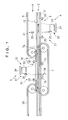
- Figure 1 is a schematic longitudinal cross sectional view of a coin discriminating apparatus which is an embodiment of the present invention.
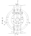
- Figure 2 is a schematic plan view of a first transparent passage portion.
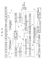
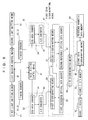
- Figure 3 is a block diagram of detection, control, memory and discrimination systems of a coin discriminating apparatus which is an embodiment of the present invention.
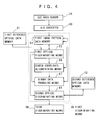
- Figure 4 is a block diagram of a first discriminating means.
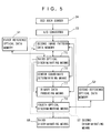
- Figure 5 is a block diagram of a second discriminating means.
- Figure 6 is a block diagram of detection, control and discrimination systems of a coin discriminating apparatus which is another embodiment of the present invention.
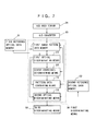
- Figure 7 is a block diagram of a first discriminating means.
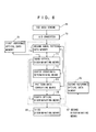
- Figure 8 is a block diagram of a second discriminating means.
- Figure 9 is a schematic view showing a method for calculating the center coordinate of pattern data effected by a center coordinate calculating section.
- Figure 10 is a view showing one example of pattern data of a coin produced by a CCD area sensor and mapped and stored in an image pattern data memory.
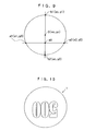
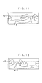
- Figure 11 is a view showing converted pattern data produced by transforming the pattern data shown in Figure 10 into an r- ⁇ coordinate system by pattern data conversion.
- Figure 12 a view showing reference pattern data of the coin shown in Figure 10 mapped in an r - ⁇ coordinate system.
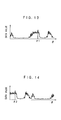
- Figure 13 is a graph showing pattern data values obtained by reading the converted pattern data shown in Figure 11 over 360 degrees at a predetermined distance r0 from a data center.
- Figure 14 is a graph showing pattern data values obtained by reading reference pattern data shown in Figure 12 over 360 degrees at a predetermined distance r0 from the data center.
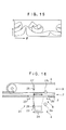
- Figure 15 is a view showing converted pattern data after remapping.
- Figure 16 is a schematic front view of a coin discriminating apparatus which is a further embodiment of the present invention.
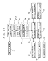
- Figure 17 is a block diagram of detection, control, memory and discrimination systems of a coin discriminating apparatus which is a further embodiment of the present invention.
- Figure 18 is a block diagram of a first coin discriminating means.
- a coin passage 2 through which coins 1 are transported is provided with a coin passage member 3 extending along a transportation direction of coins 1.
- the coin discriminating apparatus is provided with a first pattern data detection unit 4 and a second pattern data detection unit 5.
- the coin passage 2 is formed by the coin passage member 3 located in the lower portion and a transporting belt 6 constituted by an endless-like round belt located in the upper portion.
- the coin passage 2 is formed by a transporting belt 7 located to project above the coin passage member 3 from an opening 7a formed in the coin passage member 3 and constituted by an endless-like round belt and a coin passage forming member 8 located above the transporting belt 7 and extending in the transportation direction of coins 1.
- the coin passage member 3 provided with the first pattern data detection unit 4 is formed with a first transparent passage portion 9 made of glass, acrylic resin or the like, and the coin passage forming member 8 is formed with a second transparent passage portion 10 made of glass, acrylic resin or the like.
- Figure 2 is a schematic plan view of a first transparent passage portion.
- a coin is fed by the transporting belt 6 located above the coin passage 2 along a pair of guide rails 11, 11 in the direction indicated by an arrow A toward the first transparent passage portion 9 in the coin passage 2.
- a magnetic sensor 12 including transmitting coil 12a and receiving coin 12b pair is provided for detecting magnetic properties of coins 1 and producing magnetic data of coins 1 in the widthwise direction of the coin passage 2.
- a coin 1 is pressed onto the surface of the first transparent passage portion 9 by a transporting belt 6 and transported in the coin passage 2.
- a first light emitting means 21 including a plurality of light emitting elements 20 is provided for emitting light toward the lower surface of the coin 1 passing through the first transparent passage portion 9 and a first image data producing unit 22 is further provided below the first light emitting means 21 for receiving light emitted from the first light emitting means 21 and reflected by the lower surface of the coin 1 and producing image data.
- a first pattern data detection unit 4 is constituted by the first light emitting means 21 and the first image data producing unit 22.
- the first light emitting means 21 is provided with the plurality of light emitting elements 20 such as light emitting diodes (LEDs) disposed on a circle whose center is at the center portion of the first transparent passage portion 9.
- Each light emitting element 20 is disposed in such a manner that the optical axis thereof is directed at a small angle with respect to the horizontal direction toward a predetermined point on a vertical axis passing through the center of a circle whose center coincides with the center portion of the first transparent passage portion 9, whereby light is projected onto the lower surface of the coin 1 passing through the first transparent passage portion 9 at a shallow angle with respect to the lower surface of the coin 1.
- the first image data producing unit 22 includes a lens system 23 disposed so that the optical axis thereof coincides with the vertical axis passing through the center of the circle whose center coincides with the center portion of the first transparent passage portion 9, a CCD area sensor 24 disposed below the lens system 23 so that the focus point thereof is located on the upper surface of the first transparent passage portion 9 and adapted for photoelectrically detecting light emitted from the light emitting elements 20 and reflected by the lower surface of the coin 1, and an A/D converter (not shown) for converting image data of the lower surface of the coin 1 obtained by photoelectrically detecting by the CCD area sensor 24 into digital signals, thereby producing digitized image data of the lower surface of the coin 1.
- two sets of timing sensors 27, 27 each of which includes a light emitting element 25 and a light receiving element 26 are provided in the widthwise direction of the coin passage 2 so that light emitted from the light emitting element 25 can be detected through the first transparent passage portion 9 by the light receiving element 26 and each is constituted so as to output a timing signal when the light receiving element 26 does not receive light emitted from the light emitting element 25.
- Each set of the timing sensors 17 is disposed with respect to the first image data producing unit 22 so that the center of the coin 1 is located at the center of the first transparent passage portion 9 when light emitted from the light emitting element 25 is blocked by the coin 1 being transported on the surface of the first transparent passage portion 9 and is not received by the light receiving element 26, thereby outputting a timing signal.
- a coin 1 is fed up to the first transparent passage portion 9 and the downstream portion thereof, while it is being pressed onto the upper surface of the coin passage member 3 by the transporting belt 6 located above the coin passage 2.
- a coin 1 comes to be supported by the transporting belt 7 located so as to project above the coin passage member 3 from an opening 7a formed in the coin passage member 3 and transported in the coin passage 2, while it is being held between the transporting belt 6 and the transporting belt 7.
- the second pattern data detection unit 5 is provided above the second transparent passage portion 10 and includes a second light emitting means 31 provided with a plurality of light emitting elements 30 for projecting light onto the coin 1 passing through the second transparent passage portion 10 and a second image data producing unit 32 disposed above the second transparent passage portion 10 for receiving light emitted from the second light emitting means 31 and reflected by the coin 1 and producing image data.
- the second light emitting means 31 is constituted in a similar manner to the first light emitting means 7 except that it is disposed above the second transparent passage portion 4 and emits light downwardly and includes the plurality of light emitting elements 30 such as light emitting diodes (LEDs) arranged on the circle whose center coincides with the center portion of the second transparent passage portion 10.
- LEDs light emitting diodes
- Each light emitting element 30 is disposed in such a manner that the optical axis thereof is directed at a small angle with respect to the horizontal direction toward a predetermined point on a vertical axis passing through the center of the circle whose center coincides with the center portion of the second transparent passage portion 4, whereby light is projected onto the upper surface of the coin 1 passing through the second transparent passage portion 10 at a shallow angle with respect to the upper surface of the coin 1.
- the second image data producing unit 32 includes a lens system 33 disposed so that the optical axis thereof coincides with the vertical axis passing through the center of the circle whose center coincides with the center portion of the second transparent passage portion 10, a CCD area sensor 34 disposed above the lens system 33 so that the focus point thereof is located on the upper surface of the coin 1 passing through the second transparent passage portion 10 and adapted for photoelectrically detecting light emitted from the light emitting elements 30 and reflected by the surface of the coin 1, and an A/D converter (not shown) for converting image data of the upper surface of the coin 1 obtained by photoelectrically detecting by the CCD area sensor 34 into digital signals, thereby producing digitized image data of the upper surface of the coin 1.
- two sets of timing sensors 37, 37 each of which includes a light emitting element 35 and a light receiving element 36 are provided so that light emitted from the light emitting element 35 can be detected through the second transparent passage portion 10 by the light receiving element 36 and each is constituted so as to output a timing signal when the light receiving element 36 does not receive light emitted from the light emitting element 35.
- Each of the timing sensors 37 is disposed with respect to the second image data producing unit 32 so that the center of the coin 1 is located at the center of the second transparent passage portion 10 when light emitted from the light emitting element 35 is blocked by the coin 1 being transported on the surface of the second transparent passage portion 10 and is not received by the light receiving element 36, thereby outputting a timing signal.
- a transporting belt 39 extending from the immediately upstream portion of the coin passage forming member 8 toward the downstream portion of the coin passage 2 is provided. After a coin 1 has passed through the second transparent passage portion 10, the coin 1 is held between the transporting belt 7 and the transporting belt 39, and is then held between the transporting belt 39 and the coin passage member 3, thereby being transported downstream in the coin passage 2.
- Figure 3 is a block diagram of detection, control, memory and discrimination systems of a coin discriminating apparatus which is an embodiment of the present invention.
- the detection system of the coin discriminating apparatus includes the two sets of timing sensors 27, 27 for detecting a coin 1 fed to the first transparent passage portion 9 and the two sets of timing sensors 37, 37 for detecting a coin fed to the second transparent passage portion 10.
- the detection system of the coin discriminating apparatus further includes the magnetic sensor 12 comprising the transmitting coil 12a and receiving coil 12b pair for detecting magnetic properties of a coin 1 and producing magnetic data of the coin 1, the CCD area sensor 24 for receiving light reflected by the lower surface of a coin 1 and producing image pattern data of the lower surface of the coin 1, and the CCD area sensor 34 for receiving light reflected by the upper surface of a coin 1 and producing image pattern data of the upper surface of the coin 1.
- the reference numeral 63 designates an A/D converter for digitizing analog image pattern data of a coin 1 produced by the CCD area sensor 24 and the reference numeral 73 designates an A/D converter for digitizing analog image pattern data of a coin 1 produced by the CCD area sensor 34.
- the control system of the coin discriminating apparatus includes light emission control means 40 which outputs a light emission signal to the first light emitting means 21 when the timing signal from the timing sensors 27, 27 is received and causes it to emit light and illuminate the coin 1 located on the upper surface of the first transparent passage portion 9 and outputs a light emission signal to the second light emitting means 31 when the timing signal from the timing sensors 37, 37 is received and causes it to emit light and illuminate the coin 1 located on the upper surface of the second transparent passage portion 10, and image reading control means 41 for permitting the CCD area sensor 24 of the first image data producing unit 22 to start detecting the light reflected from the surface of the coin 1 when the timing signal from the timing sensors 27, 27 is received and permitting the CCD area sensor 34 of the second image data producing unit 32 to start detecting the light reflected from the surface of the coin 1 when the timing signal from the timing sensors 37, 37 is received.
- light emission control means 40 which outputs a light emission signal to the first light emitting means 21 when the timing signal from the timing sensors 27, 27 is received and causes it to emit light and
- the memory system of the coin discriminating apparatus includes a reference magnetic data memory 50 for storing reference magnetic data indicating magnetic properties of the observe and reverse surfaces of all denominations of coins, a first reference optical data memory 51 for storing reference data relating to diameters of all denominations of coins, and a second reference optical data memory 52 for storing reference ratio data indicating the ratio of data "0" in the binary image pattern data groups corresponding to a plurality of annular areas on the obverse and reverse surfaces of all denominations of coins 1.
- the memory system of the coin discriminating apparatus includes a magnetic data memory 53 for storing magnetic data of a coin 1 produced by the magnetic sensor 12.
- the discriminating system of the coin discriminating apparatus includes a first coin discriminating means 61 including a first discriminating means 56 for discriminating, based on image pattern data of the lower surface of a coin 1 produced by the first image data producing unit 22, whether or not the coin 1 is acceptable and the denomination of the coin 1 and whether the lower surface of the coin 1 is an obverse surface or a reverse surface of the coin 1, a second discriminating means 57 for discriminating, based on image pattern data of the upper surface of a coin 1 produced by the second image data producing unit 32, whether or not the coin 1 is acceptable and the denomination of the coin 1 and whether the upper surface of the coin 1 is an obverse surface or a reverse surface of the coin 1, a third discriminating means 58 for determining based on the results of discrimination made by the first discriminating means 56 and the second discriminating means 57 that the denomination of a coin 1 coincides with the denomination discriminated by the first discriminating means 56 and the second discriminating means 57 when the denomination of the coin 1 discriminated by the first
- Figure 4 is a block diagram of the first discriminating means 56.
- the first discriminating means 56 includes a first image pattern data memory 64 for mapping and storing the image pattern data of the lower surface of the coin 1 photoelectrically detected by the CCD area sensor 24 of the first image data producing unit 22 and digitized by the A/D converter 63 into an orthogonal coordinate system, i.e., an x-y coordinate system; first optical discriminating means 65 for reading the reference data relating to the diameter of the coin of each denomination stored in the first reference optical data memory 51 and comparing them with the image pattern data of the coin 1 stored in the first image pattern data memory 64, thereby discriminating whether or not the coin 1 is acceptable and the denomination of the coin 1; a center coordinate determining means 66 for obtaining the center coordinates of the image pattern data of the coin 1 mapped and stored in the first image pattern data memory 64; a binary data producing means 67 which binarizes the image pattern data of the coin 1 mapped and stored in the first image pattern data memory 64 and groups the binarized image pattern data into binary image pattern data groups corresponding to a
- Figure 5 is a block diagram of the second discriminating means 57.
- the second discriminating means 57 includes a second image pattern data memory 74 for mapping and storing the image pattern data of the upper surface of the coin 1 photoelectrically detected by the CCD area sensor 34 of the second image data producing unit 32 and digitized by the A/D converter 73 into an orthogonal coordinate system, i.e., an x-y coordinate system; third optical discriminating means 75 for reading the reference data relating to the diameter of the coin of each denomination stored in the first reference optical data memory 51 and comparing them with the image pattern data of the coin 1 stored in the second image pattern data memory 74, thereby discriminating whether or not the coin is acceptable and the denomination of the coin 1; a center coordinate determining means 76 for obtaining the center coordinates of the image pattern data of the coin 1 mapped and stored in the second image pattern data memory 74; a binary data producing means 77 which binarizes the image pattern data of the coin 1 mapped and stored in the second image pattern data memory 74 and groups the binarized image pattern data into binary image pattern data groups
- the thus constituted coin discriminating apparatus discriminates whether or not a coin 1 is acceptable and the denomination of the coin 1.
- a coin 1 is fed along the pair of guide rails 11, 11 in the coin passage 2 in the direction indicated by an arrow A, while it is being pressed onto the surface of the coin passage 2 by the transporting belt 6 and magnetic properties of the coin 1 are detected by the magnetic sensor 12, thereby producing magnetic data.
- the thus produced magnetic data are stored in the magnetic data memory 53.
- timing signals are output from the timing sensor 27 to the light emission control means 40 and the image reading control means 41.
- the light emission control means 40 When the timing signals are input from the timing sensors 27, 27, the light emission control means 40 outputs a light emission signal to the first light emitting means 21 and causes the light emitting elements 20 to emit light toward the lower surface of the coin 1 located on the first transparent passage portion 9.
- the image reading control means 41 causes the CCD area sensor 24 of the first image data producing unit 22 to detect light emitted from the light emitting elements 20 and reflected by the lower surface of the coin 1.
- the light emitting elements 20 are disposed so as to be able to illuminate the coin 1 which advances on the first transparent passage portion 9 at a shallow angle, the light is reflected according to the raised and depressed pattern of the lower surface of the coin 1.
- the light reflected from the surface of the coin 1 is directed toward the CCD area sensor 24 by the lens system 23 and photoelectrically detected by the CCD area sensor 24, whereby the image pattern data of the lower surface of the coin 1 are produced by the CCD area sensor 24.
- the image pattern data of the lower surface of the coin 1 produced by the CCD area sensor 24 are digitized by the A/D converter 63.
- the digitized image pattern data are mapped and stored in the orthogonal coordinate system, namely, x-y coordinate system in the first image pattern data memory 64.
- the first optical discriminating means 65 accesses the first reference optical data memory 51. It reads the data stored in the first reference optical data memory 51 with regard to the diameter of the coin 1 and also the image pattern data stored in the first image pattern data memory 64. By comparing those data, the first optical discriminating means 65 determines the denomination of the coin 1 and outputs the result of the discrimination to the second optical discriminating means 68.
- the center coordinate determining means 66 determines the center coordinate of the image pattern data mapped and stored in the orthogonal coordinate system, namely, the x-y coordinate system and stored in the first image pattern data memory 64 and outputs the center coordinate to the binary data producing means 67.
- the binary data producing means 67 reads the image pattern data of the lower surface of the coin 1 mapped and stored in the first image pattern data memory 64 and binarizes them.
- the binary data producing means 67 groups the binarized image pattern data into the binary image pattern data groups of the denomination corresponding to the plurality of annular areas of the surface of the coin 1 based on the result of the discrimination made by the first optical discriminating means 65 and the center coordinate input from the center coordinate determining means 66.
- the binary data producing means 67 further obtains the number of the "0" data in each binary image pattern data group corresponding to each annular area, obtains the ratio of the "0" data with respect to all the data, produces the ratio data of each binary image pattern data group corresponding to each annular area of the surface of the coin 1 and outputs the ratio data to the second optical discriminating means 68.
- the second optical discriminating means 68 accesses the second reference optical data memory 52, reads the reference ratio data of the reverse surface of a coin having the denomination corresponding to that determined by the first optical discriminating means 65 from among the reference ratio data stored in the second reference optical data memory 52, and compares them with the ratio data input from the binary data producing means 67, thereby discriminating the denomination of the coin 1.
- the second optical discriminating means 68 determines whether or not the absolute values Di of the differences between the reference ratio data of each binary image pattern group corresponding to each annular area of the coin 1 and the ratio data input from the binary data producing means 67 are less than a predetermined value D0.
- the second optical discriminating means 68 further integrates the absolute values Di of the differences between the reference ratio data and the ratio data over all of the binary image pattern data groups corresponding to the annular areas of the coin 1, and determines whether or not the resulted integrated value I is less than a predetermined value I0.
- the second optical discriminating means 68 determines that the coin 1 is the coin of the denomination determined by the first optical discriminating means 65.
- the denomination of the coin 1 coincides with the denomination determined by the first optical discriminating means 65, theoretically, the absolute value Di and the integrated value I become 0. However, because the surface of the coin 1 may be worn out or a detecting error may exist, they may not be equal to 0 even if the determined denominations coincide. Therefore, in this embodiment, when Di is less than D0 and, at the same time, I is less than I0, it is determined that the coin 1 is the coin of the denomination determined by the first optical discriminating means 65.
- the coin 1 cannot be always fed such that its obverse surface faces upward and there are cases where the obverse surface of the coin 1 faces downward while it is advanced in the coin passage 2. As a result, there is a possibility that the surface pattern of the obverse surface of the coin 1 may be detected by the CCD area sensor 24. Therefore, to determine that the coin 1 is not acceptable when the ratio data of the coin 1 input from the binary data producing means 67 do not coincide with the reference ratio data of the reverse surface of the coin of the denomination determined by the first optical discriminating means 65 will significantly lower discriminating accuracy.
- the second optical discriminating means 68 further accesses the second reference optical data memory 52, reads the reference ratio data of the obverse surface of the coin of the denomination determined by the first optical discriminating means 65, and, in the exactly same manner as described above, it determines whether or not the absolute values Di of the differences between the reference ratio data of each binary image pattern group corresponding to each annular area of the coin 1 and the ratio data input from the binary data producing means 67 are less than a predetermined value D0.
- the second optical discriminating means 68 integrates the absolute values Di of the differences between the reference ratio data of all the binary image pattern groups corresponding to each annular area of the coin 1 and the ratio data, and determines whether or not the resulted integrated value I is less than the predetermined value I0. As a result, when the integrated value I is less than the predetermined value I0, the second optical discriminating means 68 determines that the coin 1 is the coin of the denomination determined by the first optical means 65.
- the second optical discriminating means 68 of the first discriminating means 56 outputs with to the third discriminating means 58 as a first discrimination signal the result of discrimination as to whether or not the coin 1 is acceptable, the denomination of the coin 1 when the coin 1 is acceptable and with which of the obverse surface reference ratio data and the reverse surface reference ratio data the detected ratio data of the coin 1 coincides.
- the coin 1 is further fed downstream in the coin passage 2 by the transporting belt 6 and the lower surface thereof is supported by the transporting belt 7 disposed so as to project above the coin passage member 3 from the opening 7a formed in the coin passage member 3.
- the coin 1 is held between the transporting belt 6 and the transporting belt 7 to be transported and it is then fed to the second transparent passage portion 10 while it is being pressed onto the lower surface of the coin passage forming member 8.
- timing signals are output from the timing sensor 37 to the light emission control means 40 and the image reading control means 41.
- the light emission control means 40 When the timing signals are input from the timing sensors 37, 37, the light emission control means 40 outputs a light emission signal to the second light emitting means 31 and causes the light emitting elements 30 to emit light toward the upper surface of the coin 1 located on the second transparent passage portion 10.
- the image reading control means 41 causes the CCD area sensor 34 of the second image data producing unit 32 to detect light emitted from the light emitting elements 30 and reflected by the upper surface of the coin 1.
- the light emitting elements 30 are disposed so as to be able to illuminate the coin 1 which advances on the second transparent passage portion 10 at a shallow angle, the light is reflected according to the raised and depressed pattern of the upper surface of the coin 1.
- the light reflected from the surface of the coin 1 is directed toward the CCD area sensor 34 by the lens system 33 and photoelectrically detected by the CCD area sensor 34, whereby the image pattern data of the upper surface of the coin 1 are produced by the CCD area sensor 34.
- the image pattern data of the upper surface of the coin 1 produced by the CCD area sensor 34 are digitized by the A/D converter 73.
- the digitized image pattern data are mapped and stored in the orthogonal coordinate system, namely, x-y coordinate system in the second image pattern data memory 74.
- the third optical discriminating means 75 of the second discriminating means 57 accesses the first reference optical data memory 51. It reads the data stored in the with regard to the diameter of the coin 1 and also the image pattern data stored in the first image pattern data memory 74. By comparing those data, the third optical discriminating means 75 determines the denomination of the coin 1 and outputs the result of the discrimination to the fourth optical discriminating means 78.
- the center coordinate determining means 76 determines the center coordinate of the image pattern data mapped and stored in the orthogonal coordinate system, namely, the x-y coordinate system and stored in the second image pattern data memory 74 and outputs the center coordinate to the binary data producing means 77.
- the binary data producing means 77 reads the image pattern data of the upper surface of the coin 1 mapped and stored in the second image pattern data memory 74 and binarizes them.
- the binary data producing means 77 groups the binarized image pattern data into the binary image pattern data groups of the denomination corresponding to the plurality of annular areas of the surface of the coin 1 based on the result of the discrimination input from the third optical discriminating means 75 and the center coordinate input from the center coordinate determining means 76.
- the binary data producing means 77 further obtains the number of the "0" data in each binary image pattern data group corresponding to each annular area, obtains the ratio of the "0" data with respect to all the data, produces the ratio data of each binary image pattern data group corresponding to each annular area of the surface of the coin 1 and outputs the ratio data to the fourth optical discriminating means 78.
- the fourth optical discriminating means 78 accesses the second reference optical data memory 52, reads the reference ratio data of both surfaces of a coin whose denomination corresponds to that determined by the third optical discriminating means 75 from among the reference ratio data stored in the second reference optical data memory 52, and compares them with the ratio data input from the binary data producing means 77, thereby discriminating whether or not the coin 1 is acceptable and the denomination of the coin 1 in the exactly same manner as the second optical discriminating means 68 of the first discriminating means 56.
- the fourth optical discriminating means 78 accesses the second reference optical data memory 52, reads the reference ratio data of both surfaces of a coin having the denomination determined by the third optical discriminating means 75 in accordance with the result of discrimination made by the third optical discriminating means 75 from among the reference ratio data stored in the second reference optical data memory 52, and compares them with the ratio data input from the binary data producing means 77, thereby discriminating whether or not the coin 1 is acceptable and the denomination of the coin 1 in the exactly same manner as the second optical discriminating means 68 of the first discriminating means 56.
- the fourth optical discriminating means 78 of the second discriminating means 57 outputs to the third discriminating means 58 as a second discrimination signal the result of discrimination as to whether or not the coin 1 is acceptable, the denomination of the coin 1 when the coin 1 is acceptable and with which of the obverse surface reference ratio data and the reverse surface reference ratio data the detected ratio data of the coin 1 coincides.
- the third discriminating means 58 first discriminates whether the coin 1 has been discriminated to be acceptable based on the first discrimination signal input from the second optical discriminating means 68 of the first discriminating means 56 and the second discrimination signal input from the fourth optical discriminating means 78 of the second discriminating means 57.
- the third discriminating means 58 discriminates the coin 1 to be unacceptable.
- the third discriminating means 58 judges, based on the first discrimination signal input from the second optical discriminating means 68 of the first discriminating means 56 and the second discrimination signal input from the fourth optical discriminating means 78 of the second discriminating means 57, whether the second optical discriminating means 68 of the first discriminating means 56 determined the coin 1 to be acceptable based on the obverse surface reference ratio data or the reverse surface reference ratio data of a coin of the denomination, and whether the fourth optical discriminating means 78 of the second discriminating means 57 determined the coin1 to be acceptable based on the obverse surface reference ratio data or the reverse surface reference ratio data of a coin
- the third discriminating means 58 discriminates the coin 1 to be unacceptable.
- the third discriminating means 58 outputs the denomination determined by the second optical discriminating means 68 of the first discriminating means 56 and the fourth optical discriminating means 78 of the second discriminating means 57 to the second coin discriminating means 62 as a denomination discrimination signal and judges, in accordance with the first discrimination signal input from the second optical discriminating means 68 of the first discriminating means 56 or the second discrimination signal input from the second optical discriminating means 68 of the first discriminating means 56 or the second discrimination signal input from the fourth optical discriminating means 78 of the second discriminating means 57, which surface reference ratio data of a coin of the denomination was used by whichever of the first discriminating means 56 and the second discriminating means 57 discriminated the coin 1 to be acceptable based on image pattern data of the surface of the coin 1 on
- the second image data producing unit 32 produced the image pattern data of the surface of the coin 1 on the side of the transmitting coil 12a of the magnetic sensor 12 and the fourth optical discriminating means 78 of the second discriminating means 57 made the discrimination of the coin 1 based on the image pattern data of the coin 1 of this surface. Therefore, the third discriminating means 58 judges which surface reference ratio data of a coin of the denomination was used by the fourth optical discriminating means 78 of the second discriminating means 57 to discriminate the coin 1 to be acceptable and outputs the surface determination signal to the second coin discriminating means 62.
- the second coin discriminating means 62 reads out the reference magnetic data of the obverse surface or the reverse surface of a coin of the denomination discriminated by the third discriminating means 58 from the reference magnetic data memory 50, reads out the magnetic data of the coin 1 produced by detecting magnetic properties of the coin 1 by the magnetic sensor 12 and stored in the magnetic data memory 53, and compares the two sets of data.
- the second coin discriminating means 62 judges with reference to the predetermined threshold value that the reference magnetic data of the surface of a coin of the denomination and the magnetic data of the coin 1 do not coincide, it finally discriminates the coin to be unacceptable.
- the second coin discriminating means 62 judges with reference to the predetermined threshold value that the reference magnetic data of the surface of a coin of the denomination and the magnetic data of the coin 1 coincide, it finally discriminates that the denomination of the coin 1 coincides with that discriminated by the third discriminating means 58.
- the first image data producing unit 22 produces the image pattern data of one surface of a coin 1 and the second image data producing unit 32 produces the image pattern data of the other surface of the coin 1.
- the first discriminating means 56 of the first coin discriminating means 61 compares the image pattern data of the one surface of the coin 1 and the reference ratio data of the obverse and reverse surfaces of coins of each denomination and determines whether or not the coin 1 is acceptable, and the denomination of the coin 1 when the coin 1 is acceptable and the second discriminating means 57 of the first coin discriminating means 61 compares the image pattern data of the other surface of the coin 1 and the reference ratio data of the obverse and reverse surfaces of coins of each denomination and determines whether or not the coin 1 is acceptable and the denomination of the coin 1 when the coin 1 is acceptable.
- the third discriminating means 58 When the denomination of the coin 1 determined by the first discriminating means 56 and that of the coin 1 determined by the second discriminating means 57, the third discriminating means 58 outputs the denomination of the coin 1 to the second coin discriminating means 62 as a denomination determination signal, and judges, in accordance with the first discrimination signal input from the second optical discriminating means 68 or the second discrimination signal input from the fourth optical discriminating means 78, which surface reference ratio data of a coin of the denomination was used by the second discriminating means 57 the one of the first discriminating means 56 and the second discriminating means 57 that determined the coin 1 based on the image pattern data of the surface of a coin 1 on the side of the transmitting coil 12a of the magnetic sensor 12 to discriminate the coin 1 to be acceptable, thereby outputting a surface determination signal to the second coin discriminating means 62.
- the second coin discriminating means 62 Based on the denomination discrimination signal and the surface determination signal input from the third discriminating means 58, the second coin discriminating means 62 reads out the reference ratio data of the obverse surface or the reverse surface of a coin of the denomination discriminated by the third discriminating means 58 from the reference magnetic data memory 50, reads out the magnetic data of the coin 1 produced by detecting magnetic properties of the coin 1 by the magnetic sensor 12 and stored in the magnetic data memory 53, and compares the two sets of data, thereby finally discriminating whether or not the coin 1 is acceptable and the denomination of the coin 1 when the coin 1 is acceptable.
- the first coin discriminating means 61 discriminates whether or not the coin 1 is acceptable and the denomination of the coin 1 based on the image pattern data of both surfaces of the coin 1 and the second coin discriminating means 62 reads out, based on the denomination of the coin 1 determined by the third discriminating means 58, the reference ratio data of a coin from the reference magnetic data memory 50, the second coin discriminating means 62 can discriminate whether or not the coin 1 is acceptable and the denomination of the coin 1 based on the reference magnetic data of a proper denomination, thereby improving the discrimination accuracy of coins.
- the second coin discriminating means 62 reads out from the reference magnetic data memory 50 the reference magnetic data corresponding to the surface of a coin of the reference optical data employed by the second discriminating means 57, which determined the denomination of the coin 1 and discriminates whether or not the coin 1 is acceptable and the denomination of the coin 1. Therefore, even when image pattern data of a counterfeit coin coincides with image pattern data of a coin of a certain denomination and the magnetic properties of the counterfeit coin are similar to those of the denomination of the coin, it is possible to discriminate the counterfeit coin with high accuracy.
- Figure 6 is a block diagram showing a detecting system, a control system, a memory system and a discriminating system of a coin discriminating apparatus which is another preferred embodiment of the present invention.
- the detection system of the coin discriminating apparatus includes timing sensors 27, 27, timing sensors 37, 37, a CCD area sensor 24 and a CCD area sensor 34.
- control system of the coin discriminating apparatus includes light emission control means 40 and image reading control means 41.
- the memory system of the coin discriminating apparatus includes the reference magnetic data memory 50, a first optical data memory 51 for storing reference data relating to diameters of each denomination of coins, a second reference optical data memory 52 and a magnetic data memory 53 for storing magnetic data of a coin 1 produced by the magnetic sensor 12.
- the second reference optical data memory 52 stores pattern data of both surfaces for each denomination mapped into an r- ⁇ coordinate system.
- the discriminating system of the coin discriminating apparatus includes a first coin discriminating means 61 including a first discriminating means 56 for discriminating, based on image pattern data of the lower surface of a coin 1 produced by the first image data producing unit 22, whether or not the coin 1 is acceptable and the denomination of the coin 1 and whether the lower surface of the coin 1 is an obverse surface or a reverse surface of the coin 1, a second discriminating means 57 for discriminating, based on image pattern data of the upper surface of a coin 1 produced by the second image data producing unit 32, whether or not the coin 1 is acceptable and the denomination of the coin 1 and whether the upper surface of the coin 1 is an obverse surface or a reverse surface of the coin 1, a third discriminating means 58 for determining based on the results of discrimination made by the first discriminating means 56 and the second discriminating means 57 that the denomination of a coin 1 coincides with the denomination discriminated by the first discriminating means 56 and the second discriminating means 57 when the denomination of the coin
- Figure 7 is a block diagram showing the first discriminating means 56.
- the first discriminating means 56 includes a first image pattern data memory 64 for mapping and storing the image pattern data of the lower surface of the coin 1 photoelectrically detected by the CCD area sensor 24 of the first image data producing unit 22 and digitized by the A/D converter 63 into an orthogonal coordinate system, i.e., an x-y coordinate system; a first optical discriminating means 65 for reading the reference data relating to the diameter of the coin of each denomination stored in the first reference optical data memory 51 and comparing them with the image pattern data of the coin 1 stored in the first image pattern data memory 64, thereby discriminating whether or not the coin is acceptable and the denomination of the coin 1; a center coordinate determining means 66 for obtaining the center coordinates of the image pattern data of the coin 1 mapped and stored in the first image pattern data memory 64; a pattern data converting means 70 for converting pattern data by transforming into the polar coordinate system, namely, the r- ⁇ coordinate system, based on the center coordinate of the pattern data calculated by the center coordinate determining
- Figure 8 is a block diagram showing the second discriminating means 57.
- the second discriminating means 57 includes a second image pattern data memory 74 for mapping and storing the image pattern data of the upper surface of the coin 1 photoelectrically detected by the CCD area sensor 34 of the first image data producing unit 32 and digitized by the A/D converter 73 into an orthogonal coordinate system, i.e., an x-y coordinate system; third optical discriminating means 75 for reading the reference data relating to the diameter of the coin of each denomination stored in the first reference optical data memory 51 and comparing them with the image pattern data of the coin 1 stored in the second image pattern data memory 74, thereby discriminating whether or not the coin is acceptable and the denomination of the coin 1; center coordinate determining means 76 for obtaining the center coordinates of the image pattern data of the coin 1 mapped and stored in the second image pattern data memory 74; pattern data converting means 80 for converting pattern data by transforming into the polar coordinate system, namely, the r- ⁇ coordinate system, based on the center coordinate of the pattern data calculated by the center coordinate determining means
- Figure 9 is a schematic view showing a method for determining the center coordinate of pattern data effected by the center coordinate determining means 66.
- the pattern data of the coin 1 produced by the CCD area sensor 24 are mapped in the x-y coordinate system and stored in the first image pattern data memory 64.
- the thus determined coordinates (xc, yc) of the data O corresponds to the center coordinate of the pattern data of the coin 1 mapped in the x-y coordinate system and the data O corresponds to the data center of the pattern data of the coin 1 mapped in the x-y coordinate system.
- the method for determining the center coordinate of pattern data effected by the center coordinate determining means 76 is exactly the same as that effected by the center coordinate determining means 66.
- Figure 10 is a view showing one example of pattern data of the coin 1 produced by the CCD area sensor 24 and mapped and stored in the first image pattern data memory 64 and
- Figure 11 is a view showing converted pattern data produced by transforming the pattern data shown in Figure 10 into the r- ⁇ coordinate system by pattern data converting means 70 based upon the center coordinate (xc, yc) of the pattern data of the coin 1 determined by the center coordinate determining means 66.
- the ordinate represents the distance r from the data center O in the x-y coordinate system and the abscissa represents an angle ⁇ about the data center O.
- An example of pattern data of the coin 1 produced by the CCD area sensor 34 and mapped and stored in the second image pattern data memory 74 is similar to the above and an example of converted pattern data produced by transforming the pattern data into the r- ⁇ coordinate system by pattern data converting means 80.
- the converted pattern data transformed into the r- ⁇ coordinate system by the pattern data converting means 70 in this manner are input to the second optical discriminating means 68.
- the second optical discriminating means 68 selects, based on the result of discrimination made by the first optical discriminating means 65, the reference pattern data of the corresponding denomination from among the reference pattern data of coins mapped in the r- ⁇ coordinate system and stored in the second reference optical data memory 52.
- the processing of image pattern data of the coin 1 effected by the second discriminating means 57 is the same as that effected by the first discriminating means 56.
- Figure 12 shows an example of the reference pattern data of the coin 1 shown in Figure 10 and mapped in the r- ⁇ coordinate system.
- This data corresponds to the converted pattern data shown in Figure 11. Since the converted pattern data shown in Figure 11 are obtained in the pattern data converting means 70 by transforming the pattern data in the x-y coordinate system into the r- ⁇ coordinate system based on the center coordinates (xc, yc) of the pattern data of the coin 1 determined by the center coordinate determining means 66, the zero point of the ordinate, namely, the zero point of the r-axis coincides with the zero point of the reference pattern data shown in Figure 12.
- the orientation of the coin 1 to be discriminated is usually offset angularly (rotationally) from that of the coin 1 used for producing the reference pattern data
- the pattern data in Figure 11 and the reference pattern data in Figure 12 at the same ⁇ value are normally obtained from different portions of the coin 1. Accordingly, it is impossible to discriminate whether or not the coin 1 is acceptable and the denomination of the coin 1 by directly comparing the converted pattern data in Figure 11 and the reference pattern data in Figure 12 and, therefore, it is necessary to correct the converted pattern data prior to the comparison so that the zero point of the converted pattern data in the ⁇ axis coincides with the zero point of the reference pattern data in the ⁇ axis.
- the second optical discriminating means 68 reads the pattern data values at a predetermined distance r0 from the data center of the converted pattern data shown in Figure 11, namely, reads the pattern data values whose ordinate values are equal to a predetermined value r0 over 360 degrees, and reads the pattern data values at a predetermined distance r0 from the data center of the reference pattern data shown in Figure 12, namely, reads the pattern data values whose ordinate values are equal to a predetermined value r0 over 360 degrees. Then, the second optical discriminating means 68 compares the two sets of pattern data values, thereby correcting the deviation of the converted pattern data in the ⁇ axis caused by the angular offset of the coin 1.
- Figure 13 is a graph showing pattern data values obtained by reading the converted pattern data shown in Figure 11 over 360 degrees at a predetermined distance r0 from the data center
- Figure 14 is a graph showing pattern data values obtained by reading reference pattern data shown in Figure 12 over 360 degrees at a predetermined distance r0 from the data center.
- the ordinate represents data values and the abscissa represents the angle.
- Coins 1 are fed through the coin passage 2, while being guided by the pair of guide rails 11, 11 and, therefore, the center of each coin 1 passes along a predetermined locus on the first transparent passage portion 9.
- the coin 1 is usually offset angularly from the coin used to produce the reference pattern data. Therefore, since the sets of pattern data at the same ⁇ value in Figures 11 and 12 are normally obtained from different portions of the coin 1, it is necessary to correct the converted pattern data prior to the comparison so that the zero point of the converted pattern data in the ⁇ axis coincides with the zero point of the reference pattern data in the ⁇ axis.
- the second optical discriminating means 68 obtains ⁇ values ⁇ 1 and ⁇ 2 at which the pattern data value shown in Figure 13 and the pattern data value shown in Figure 14 are maximum respectively and remaps the converted pattern data shown in Figure 11 so that ⁇ 1 becomes equal to ⁇ 2.
- Figure 15 shows the thus remapped converted pattern data.
- the second optical discriminating means 68 compares the converted pattern data remapped in the above described manner and shown in Figure 15 with the reference pattern data shown in Figure 12 and discriminates whether or not the coin 1 is the coin of the denomination determined by the first optical discriminating means 65 or whether or not the coin 1 is acceptable, in accordance with the extent of how well the converted pattern data coincides with the reference pattern data.
- the remapping processing of the converted pattern data effected by the fourth optical discriminating means 78 in the second discriminating means 57 is the same as that effected by the second optical discriminating means 68 in the first discriminating means 56.
- the thus constituted coin discriminating apparatus discriminates coins in the following manner.
- the coin 1 is fed in the coin passage 2 along a pair of guide rails 11, 11 in the direction indicated by an arrow A.
- the coin 1 arrives at the first transparent passage portion 9 and when light emitted from the light emitting element 25 of each timing sensor 27, 27 is blocked by the coin 1 and the light receiving element 26 does not receive the light emitted from the light emitting element 25, timing signals are output to the light emission control means 40 and the image reading control means 41.
- the light emission control means 40 When the timing signals are input from the timing sensors 27, 27, the light emission control means 40 outputs a light emission signal to the first light emitting means 21 and causes the light emitting elements 20 to emit light toward the lower surface of the coin 1 located on the first transparent passage portion 9.
- the image reading control means 41 When the timing signals are input from the timing sensors 27, 27, the image reading control means 41 outputs a reading operation start signal to the CCD area sensor 24, thereby causing it to detect light reflected by the lower surface of the coin 1.
- FIG. 10 is a view showing one example of pattern data of the lower surface of the coin 1 mapped and stored in the first image pattern data memory 64.
- the first optical discriminating means 65 accesses the first reference optical data memory 51. It reads the data stored in the first reference optical data memory 51 with regard to the diameter of the coin 1 and also reads the image pattern data of the coin 1 stored in the first image pattern data memory 64. By comparing those data, the first optical discriminating means 65 determines the denomination of the coin 1 and outputs the result of the discrimination to the second optical discriminating means 68.
- the center coordinate determining means 66 determines the center coordinate (xc, yc) of the image pattern data of the coin 1 based on the image pattern data of the coin mapped in the x-y coordinate system and stored in the first image pattern data memory 64 and outputs the center coordinate to the pattern data converting means 70.
- the pattern data converting means 70 transforms the pattern data of the coin 1 mapped in the x-y coordinate system and stored in the first image pattern data memory 64 into an r- ⁇ coordinate system and produces converted pattern data, thereby outputting them to the second optical discriminating means 68.
- Figure 12 shows one example of the converted pattern data thus transformed into the r- ⁇ coordinate system.
- the second optical discriminating means 68 selects the reference pattern data of the reverse surface of the coin 1 corresponding to the denomination from among the reference pattern data mapped into the r- ⁇ coordinate system and stored in the second reference optical data memory 52 and reads them.
- Figure 13 shows one example of the reference pattern data output from the second reference optical data memory 52 to the second optical discriminating means 68.
- the converted pattern data Since the pattern data cannot be produced by the CCD area sensor 24 with the coin 1 in a predetermined angular orientation and the coin 1 is normally offset angularly from the coin 1 used for producing the reference pattern data, as is clear from Figures 11 and 12, the converted pattern data is normally offset along the abscissa, namely, the ⁇ axis, with respect to the reference pattern data. Therefore, it is necessary to correct the deviation of the converted pattern data in the ⁇ direction in order to discriminate the coin 1 by comparing the converted pattern data with the reference pattern data.
- the second optical discriminating means 68 reads the pattern data values of the converted pattern data shown in Figure 11 over 360 degrees whose ordinate values are equal to a predetermined value r0 and reads the pattern data values of the reference pattern data shown in Figure 12 over 360 degrees whose ordinate values are equal to a predetermined value r0.
- Figures 13 and 14 are graphs obtained by plotting the thus read converted pattern data values and reference pattern data values whose ordinate values are equal to a predetermined value r0.
- the second optical discriminating means 68 further calculates ⁇ values at which the converted pattern data values and the reference pattern data values become maximum respectively.
- the thus obtained ⁇ value is ⁇ 1 in Figure 13 and the ⁇ value is ⁇ 2 in Figure 14.
- the second optical discriminating means 68 remaps the converted pattern data so that ⁇ 1 becomes equal to ⁇ 2.
- Figure 15 shows an example of the converted pattern data thus remapped by the second optical discriminating means 68. Since the deviation of the converted pattern data in the ⁇ direction caused by the angular offset of the coin 1 has been corrected by remapping the converted pattern data, it is possible for the second optical discriminating means 68 to discriminate whether the denomination of the coin 1 coincides with that determined by the first optical discriminating means 65 and whether or not the coin 1 is an unacceptable coin such as a counterfeit coin, a foreign coin or the like by pattern matching the converted pattern data with the reference pattern data.
- the remapped converted pattern data never coincides with the reference pattern data of the reverse surface of the coin 1 of the denomination determined by the first optical discriminating means 65. Therefore, when the remapped converted pattern data does not coincides with the reference pattern data of the reverse surface of the coin 1 of the denomination selected in accordance with the result of discrimination made by the first optical discriminating means 65, if the coin 1 is immediately discriminated as a counterfeit coin or a foreign coin, the coin discrimination accuracy becomes lowered.
- the converted pattern data is first compared with the reference pattern data of the reverse surface of the coin 1 of the denomination determined by the first optical discriminating means 65 and if they do not coincide, the converted pattern data is compared with the reference pattern data of the obverse surface of the coin 1 of the denomination in the same manner, thereby discriminating whether the denomination of the coin 1 coincides with that tentatively determined by the first optical discriminating means 65 and whether or not the coin 1 is an unacceptable coin such as a counterfeit coin, a foreign coin or the like.
- the result of discrimination made by the second optical discriminating means 68 in the first discriminating means 56 is output to the third discriminating means 58 as a first discrimination signal.
- the coin 1 is further fed to the second transparent passage portion 10 in the coin passage 2 and when light emitted from the light emitting element 35 of each timing sensor 37, 37 is blocked by the coin 1 and the light receiving element 36 does not receive the light emitted from the light emitting element 35, timing signals are output from the timing sensors 37, 37 to the light emission control means 40 and the image reading control means 41.
- the light emission control means 40 When the timing signals are input from the timing sensors 37, 37, the light emission control means 40 outputs a light emission signal to the second light emitting means 31 and causes the light emitting elements 30 to emit light toward the upper surface of the coin 1 located on the second transparent passage portion 10.
- the image reading control means 41 When the image reading control means 41 receives the timing signals from the timing sensors 37, 37, it causes the CCD area sensor 34 of the second image data producing unit 32 to start detecting light emitted from the light emitting elements 30 and reflected by the upper surface of the coin 1.
- the light emitting means 31 is disposed so as to be able to illuminate the coin 1 which advances on the second transparent passage portion 10 at a shallow angle, the light is reflected according to the raised and depressed pattern of the upper surface of the coin 1.
- the light reflected from the surface of the coin 1 is directed toward the CCD area sensor 34 by the lens system 33 and photoelectrically detected by the CCD area sensor 34, whereby the image pattern data of the surface of the coin 1 are produced by the CCD area sensor 34.
- the image pattern data of the surface of the coin 1 produced by the CCD area sensor 34 are digitized by the A/D converter 73.
- the digitized image pattern data are mapped and stored in the orthogonal coordinate system, namely, the x-y coordinate system, in the second image pattern data memory 74 of the second discriminating means 57.
- the third optical discriminating means 75 of the second discriminating means 57 accesses the first reference data memory 51. It reads the data stored in the first reference data memory 51 with regard to the diameter of the coin 1 and also the image pattern data of the coin 1 stored in the second image pattern data memory 74. By comparing these data, the third optical discriminating means 75 of the second discriminating means 57 determines whether or not the coin 1 is acceptable and the denomination of the coin 1.
- the center coordinate determining means 76 determines the center coordinate (xc, yc) of the image pattern data mapped in the x-y coordinate system and stored in the second image pattern data memory 74 and outputs the center coordinate (xc, yc) to the pattern data converting means 80.
- the pattern data converting means 80 transforms the pattern data of the coin 1 mapped in the x-y coordinate system and stored in the second image pattern data memory 74 into an r- ⁇ coordinate system.
- the fourth optical discriminating means 78 of the second discriminating means 57 selects the reference pattern data of the reverse surface of the coin 1 corresponding to the denomination from among the reference pattern data mapped into the r- ⁇ coordinate system and stored in the second reference optical data memory 52 and reads them.
- the fourth optical discriminating means 78 of the second discriminating means 57 corrects the deviation of the converted pattern data in the ⁇ direction and remaps the converted pattern data.
- the fourth optical discriminating means 78 of the second discriminating means 57 discriminates whether or not the coin 1 is the coin of the denomination discriminated by the third optical discriminating means 75 and whether or not the coin 1 is an unacceptable coin such as a counterfeit coin, a foreign coin or the like.
- the result of discrimination made by the fourth optical discriminating means 78 of the second discriminating means 57 is output to the third discriminating means 58 as a second discrimination signal.
- the third discriminating means 58 first determines whether or not the coin 1 has been discriminated to be acceptable based on the first discrimination signal input from the second optical discriminating means 68 of the first discriminating means 56 and the second discrimination signal input from the fourth optical discriminating means 78 of the second discriminating means 57.
- the third discriminating means 58 determines that the coin 1 is unacceptable.
- the third discriminating means 58 judges, based on the first discrimination signal input from the second optical discriminating means 68 of the first discriminating means 56 and the second discrimination signal input from the fourth optical discriminating means 78 of the second discriminating means 57, whether the second optical discriminating means 68 of the first discriminating means 56 determined the coin 1 to be acceptable based on the obverse surface reference pattern data or the reverse surface reference pattern data of a coin of the denomination, and whether the fourth optical discriminating means 78 of the second discriminating means 57 determined the coin1 to be acceptable based on the obverse surface reference pattern data or the reverse surface reference pattern data of a coin
- the third discriminating means 58 discriminates the coin 1 to be unacceptable.
- the third discriminating means 58 outputs the denomination determined by the second optical discriminating means 68 of the first discriminating means 56 and the fourth optical discriminating means 78 of the second discriminating means 57 to the second coin discriminating means 62 as a denomination discrimination signal and judges, in accordance with the first discrimination signal input from the second optical discriminating means 68 of the first discriminating means 56 or the second discrimination signal input from the fourth optical discriminating means 78 of the second discriminating means 57, which surface reference pattern data of a coin of the denomination was used by whichever of the first discriminating means 56 and the second discriminating means 57 discriminated the coin 1 to be acceptable based on image pattern data of the surface of the coin on the side of the transmitting coil 12a of the magnetic sensor 12, thereby outputting a surface determination signal to
- the second coin discriminating means 62 reads out the reference magnetic data of the obverse surface or the reverse surface of a coin of the denomination discriminated by the third discriminating means 58 from the reference magnetic data memory 50, reads out the magnetic data of the coin 1 produced by detecting magnetic properties of the coin 1 by the magnetic sensor 12 and stored in the magnetic data memory 53, and compares the two sets of data.
- the second coin discriminating means 62 judges with reference to the predetermined threshold value that the reference magnetic data of the surface of a coin of the denomination and the magnetic data of the coin 1 do not coincide, it finally discriminates that the coin is unacceptable.
- the second coin discriminating means 62 judges with reference to the predetermined threshold value that the reference magnetic data of the surface of a coin of the denomination and the magnetic data of the coin 1 coincide, it finally discriminates that the denomination of the coin 1 coincides with that discriminated by the third discriminating means 58.
- the first image data producing unit 22 produces the image pattern data of one surface of a coin 1 and the second image data producing unit 32 produces the image pattern data of the other surface of the coin 1.
- the first discriminating means 56 of the first coin discriminating means 61 compares the image pattern data of the one surface of the coin 1 and the reference optical data of the obverse and reverse surfaces of coins of each denomination and determines whether or not the coin 1 is acceptable and the denomination of the coin 1 when the coin 1 is acceptable
- the second discriminating means 57 of the first coin discriminating means 61 compares the image pattern data of the other surface of the coin 1 and the reference optical data of the obverse and reverse surfaces of coins of each denomination and determines whether or not the coin 1 is acceptable and the denomination of the coin 1 when the coin 1 is acceptable.
- the third discriminating means 58 outputs the denomination of the coin 1 to the second coin discriminating means 62 as a denomination determination signal, and judges, in accordance with the first discrimination signal input from the second optical discriminating means 68 or the second discrimination signal input from the fourth optical discriminating means 78, which surface reference ratio data of a coin of the denomination was used by the second discriminating means 57 the one of the first discriminating means 56 and the second discriminating means 57 that determined the coin 1 based on the image pattern data of the surface of a coin 1 on the side of the transmitting coil 12a of the magnetic sensor 12 to discriminate the coin 1 to be acceptable, thereby outputting a surface determination signal to the second coin discriminating means 62.
- the second coin discriminating means 62 Based on the denomination discrimination signal and the surface determination signal input from the third discriminating means 58, the second coin discriminating means 62 reads out the reference ratio data of the obverse surface or the reverse surface of a coin of the denomination discriminated by the third discriminating means 58 from the reference magnetic data memory 50, reads out the magnetic data of the coin 1 produced by detecting magnetic properties of the coin 1 by the magnetic sensor 12 and stored in the magnetic data memory 53, and compares the two sets of data, thereby finally discriminating whether or not the coin 1 is acceptable and the denomination of the coin 1 when the coin 1 is acceptable.
- the first coin discriminating means 61 discriminates whether or not the coin 1 is acceptable and the denomination of the coin 1 based on the image pattern data of both surfaces of the coin 1 and the second coin discriminating means 62 reads out, based on the denomination of the coin 1 determined by the third discriminating means 58, the reference ratio data of a coin from the reference magnetic data memory 50, the second coin discriminating means 62 can discriminate whether or not the coin 1 is acceptable and the denomination of the coin 1 based on the reference magnetic data of a proper denomination, thereby improving the discrimination accuracy of coins.
- the second coin discriminating means 62 reads out from the reference magnetic data memory 50 the reference magnetic data corresponding to the surface of a coin of the reference optical data employed by the second discriminating means 57 which has determined the denomination of the coin 1 and discriminates whether or not the coin 1 is acceptable and the denomination of the coin 1. Therefore, even when image pattern data of a counterfeit coin coincides with image pattern data of a coin of a certain denomination and the magnetic properties of the counterfeit coin are similar to those of the denomination of the coin, it is possible to discriminate the counterfeit coin with high accuracy.
- the denomination of the coin 1 and whether or not the coin 1 is acceptable are discriminated based on only the ratio of the "0" data in the binary image pattern data groups corresponding to each annular area of the coin 1. Therefore, even though the coin 1 is a counterfeit coin or a foreign coin and an unacceptable coin, the ratio data which corresponds to the ratio of the "0" data in the binary image pattern data groups corresponding to each annular area of the coin 1 may perchance to coincide with the reference ratio data of the coin of the denomination determined by the second optical discriminating means 68 and the fourth optical discriminating means 78.
- the coin 1 is discriminated by detecting the pattern of the entire surface of the coin 1 to produce the pattern data and comparing the thus produced pattern data with the reference pattern data of coin of the denomination determined by the second optical discriminating means 68 and the fourth optical discriminating means 78, the discriminating accuracy of the coin 1 can be improved.
- the deviation of the converted pattern data in the ⁇ direction caused by the angular offset of a coin 1 can be corrected only by obtaining the values ⁇ 1 and ⁇ 2 at which the respective data values of the converted pattern data and the reference pattern data become maximum and remapping the converted pattern data so that ⁇ 1 becomes equal to ⁇ 2. It is therefore possible to shorten the time for calculation, whereby coins 1 can be discriminated at high speed.
- Figure 16 is a perspective front view showing a coin discriminating apparatus which is a further preferred embodiment of the present invention.
- this embodiment is provided with a transmission-type magnetic sensor 12 whose transmitting coin 12a is disposed below the coin passage 2 and receiving coil 12b is disposed above the coin passage 2.
- Figure 17 is a block diagram of a detection system, a control system, a memory system and a discrimination system of a coin discriminating apparatus which is a further preferred embodiment of the present invention.
- the detection system of the coin discriminating apparatus includes two sets of timing sensors 27, 27 for detecting a coin 1 fed to the first transparent passage portion 9, the magnetic sensor 12 comprising the transmitting coil 12a and receiving coil 12b pair for detecting magnetic properties of coins 1 and producing magnetic data of coins 1 and a CCD area sensor 24 for receiving light reflected by the lower surfaces of coins 1 and producing image pattern data of the lower surfaces of coins 1.
- 63 designates an A/D converter for digitizing analog image pattern data of coins 1 produced by the CCD area sensor 24.
- the control system of the coin discriminating apparatus includes a light emission control means 40 which outputs a light emission signal to the first light emitting means 21 when the timing signal from the timing sensors 27, 27 is received and causes it to emit light and illuminate the coin 1 located on the upper surface of the first transparent passage portion 9 and image reading control means 41 for permitting the CCD area sensor 24 of the first image data producing unit 22 to start detecting the light reflected from the surface of the coin 1 when the timing signal from the timing sensors 27, 27 is received.
- the memory system of the coin discriminating apparatus includes a reference magnetic data memory 50 for storing reference magnetic data indicating magnetic properties of the observe and reverse surfaces of each denomination of coins to be detected, a first reference optical data memory 51 for storing reference data relating to diameters of each denomination of coins, and a second reference optical data memory 52 for storing reference pattern data of obverse surfaces and reverse surfaces of coins of each denomination, and a magnetic data memory 53 for storing magnetic data of coins 1 produced by the magnetic sensor 12.
- the discriminating system of the coin discriminating apparatus includes first coin discriminating means 81 for discriminating, based on image pattern data of the lower surface of a coin 1 produced by the first image data producing unit 22, whether or not the coin 1 is acceptable and the denomination of the coin 1 and whether the lower surface of the coin 1 is an obverse surface or a reverse surface of the coin 1, and second coin discriminating means 82 for reading from the reference magnetic data memory 50 reference magnetic data corresponding to the denomination of the coin 1 discriminated by the first coin discriminating means 81 and corresponding to the surface determined depending on whether the reference pattern data used by the first coin discriminating means 81 to discriminate that the coin 1 is acceptable and the denomination of the coin 1 are reference pattern data of an obverse surface or those of a reverse surface of the coin 1 and compares them with the magnetic data of the coin 1 produced by the magnetic sensor 12, thereby finally discriminating whether or not the coin 1 is acceptable and the denomination of the coin 1.
- Figure 18 is a block diagram showing the first coin discriminating means 81.
- the first coin discriminating means 81 includes an image pattern data memory 84 for mapping and storing the image pattern data of the lower surface of the coin 1 photoelectrically detected by the CCD area sensor 24 of the first image data producing unit 22 and digitized by the A/D converter 63 into an orthogonal coordinate system, i.e., an x-y coordinate system; first optical discriminating means 65 for reading the reference data relating to the diameter of the coin of each denomination stored in the first reference optical data memory 51 and comparing them with the image pattern data of the coin 1 stored in the image pattern data memory 84, thereby discriminating whether or not the coin is acceptable and the denomination of the coin 1; center coordinate determining means 66 for obtaining the center coordinates of the image pattern data of the coin 1 mapped and stored in the image pattern data memory 84; pattern data converting means 70 for converting pattern data by transforming into the polar coordinate system, namely, the r- ⁇ coordinate system, based on the center coordinate of the pattern data calculated
- the thus constituted coin discriminating apparatus discriminates coins in the following manner.
- the coin 1 is fed in the coin passage 2 along a pair of guide rails 11, 11 in the direction indicated by an arrow A.
- the coin 1 arrives at the first transparent passage portion 9 and when light emitted from the light emitting element 25 of each timing sensor 27, 27 is blocked by the coin 1 and the light receiving element 26 does not receive the light emitted from the light emitting element 25, timing signals are output to the light emission control means 40 and the image reading control means 41.
- the light emission control means 40 When the timing signals are input from the timing sensors 27, 27, the light emission control means 40 outputs a light emission signal to the first light emitting means 21 and causes the light emitting elements 20 to emit light toward the lower surface of the coin 1 located on the first transparent passage portion 9.
- the image reading control means 41 When the timing signals are input from the timing sensors 27, 27, the image reading control means 41 outputs a reading operation start signal to the CCD area sensor 24, thereby causing it to detect light reflected by the lower surface of the coin 1.
- the image pattern data of the lower surface of the coin 1 produced by the CCD area sensor 24 and digitized by the A/D converter 63 are mapped and stored in the x-y coordinate system in the image pattern data memory 84 similarly to the embodiment shown in Figures 6 to 15.
- the first optical discriminating means 65 accesses the first reference optical data memory 51. It reads the data stored in the first reference optical data memory 51 with regard to the diameter of the coin 1 and also reads the image pattern data of the coin 1 stored in the image pattern data memory 84. By comparing those data, the first optical discriminating means 65 determines whether or not the coin 1 is acceptable and the denomination of the coin 1 when the coin 1 is acceptable.
- the center coordinate determining means 66 determines the center coordinate (xc, yc) of the image pattern data of the coin 1 based on the image pattern data of the coin mapped in the x-y coordinate system and stored in the image pattern data memory 84 and outputs the center coordinate to the pattern data converting means 70.
- the pattern data converting means 70 transforms the pattern data of the coin 1 mapped in the x-y coordinate system and stored in the image pattern data memory 84 into an r- ⁇ coordinate system and produces converted pattern data, thereby outputting them to the second optical discriminating means 68.
- the second optical discriminating means 68 selects the reference pattern data of the reverse surface of the coin 1 corresponding to the denomination from among the reference pattern data mapped into the r- ⁇ coordinate system and stored in the second reference optical data memory 52 and reads them.
- the second optical discriminating means 68 corrects the converted pattern data of the coin 1 similarly to the embodiment shown in Figures 6 to 15 and compares them with the reference pattern data of the reverse surface of the coin of the denomination read out from the second reference optical reference data memory 52 based on the result of discrimination input from the first optical discriminating means 65.
- the second optical discriminating means 68 further reads the reference pattern data of the obverse surface of the coin of the denomination from the second reference optical reference data memory 52 based on the result of discrimination input from the first optical discriminating means 65 and compares them with the corrected converted pattern data of the coin 1. Based on the comparison, the second optical discriminating means 68 determines whether or not the coin 1 is acceptable and the denomination of the coin 1.
- the second optical discriminating means 68 discriminates that the coin 1 is unacceptable.
- the second optical discriminating means 68 outputs a discrimination signal to the second coin discriminating means 82 and also outputs to the second coin discriminating means 82 a surface discrimination signal indicating which reference pattern data, those of the obverse surface or those of the reverse surface of the denomination, it used to determine the denomination of the coin 1 based on.
- the second coin discriminating means 82 determines the denomination of the reference magnetic data to be read from the reference magnetic data memory 50 based on the discrimination signal input from the second optical discriminating means 68 of the first coin discriminating means 81 and determines whether the reference magnetic data of the obverse surface of a coin of the denomination or the reference magnetic data of the reverse surface of a coin of the denomination should be read.
- the second coin discriminating means 82 reads the thus selected reference magnetic data of the obverse surface or the reverse surface of a coin of the denomination from the reference magnetic data memory 50, reads the magnetic data of the coin 1 from the magnetic data memory 53, and compares the two sets of data.
- the second coin discriminating means 82 judges with reference to the predetermined threshold value that the reference magnetic data of the surface of a coin of the denomination and the magnetic data of the coin 1 do not coincide, it finally discriminates that the coin is unacceptable.
- the second coin discriminating means 82 judges with reference to the predetermined threshold value that the reference magnetic data of the surface of a coin of the denomination and the magnetic data of the coin 1 coincide, it finally discriminates that the denomination of the coin 1 coincides with that discriminated by the second optical discriminating means 68 of the first coin discriminating means 81.
- the reference magnetic data of the obverse surface or the reverse surface of a coin corresponding to the reference pattern data used by the first coin discriminating means 81 to discriminate whether or not the coin 1 is acceptable and the denomination of the coin 1 are compared with the magnetic data of the coin 1, whereby whether or not the coin 1 is acceptable and the denomination of the coin 1 are finally discriminated, even when image pattern data of a counterfeit coin coincides with image pattern data of a coin of a certain denomination and the magnetic properties of the counterfeit coin are similar to those of the denomination of the coin, it is possible to discriminate the counterfeit coin with high accuracy.
- the second pattern data detection unit 5 is provided downstream of the first pattern data detection unit 4 so that pattern data of the lower surface of a coin 1 are produced by the first pattern data detection unit 4 and that pattern data of the upper surface of a coin 1 are produced by the second pattern data detection unit 5, the first pattern data detection unit 4 may be provided downstream of the second pattern data detection unit 5.
- the second pattern data detection unit 5 is provided downstream of the first pattern data detection unit 4, the first pattern data detection unit 4 and the second pattern data detection unit 5 may be provided on the opposite sides of the coin passage 2 so as to face each other. In such a case, one of the two pairs of the timing sensors 27, 27 and 37, 37 may be omitted
- the magnetic sensor 12 may be provided upstream of the first pattern data detection unit 4 and the second pattern data detection unit 5 or may be provided between the first pattern data detection unit 4 and the second pattern data detection unit 5.
- the reflection-type magnetic sensor 12 is used as the magnetic sensor 12 in the embodiments shown in Figures 1 to 15 so that the transmitting coil 12a and the receiving coil 12b constituting the magnetic sensor 12 are disposed on the same side of the coin passage and the transmission type magnetic sensor 12 is used as the magnetic sensor 12 in the embodiment shown in Figures 16 to 18 so that the transmitting coil 12a and the receiving coil 12b constituting the magnetic sensor 12 are disposed on the opposite sides of the coin passage 2.
- a transmission type magnetic sensor 12 may be used in the embodiments shown in Figures 1 to 15 and a reflection type magnetic sensor 12 may be used in the embodiment shown in Figures 16 to 18.
- the timing sensors 27, 27 or the timing sensors 37, 37 detect a coin 1
- the first light emitting means 21, the second light emitting means 31 or the light emitting means 21 so as to constantly emit light
- the CCD area sensor 24 or the CCD area sensor 34 so as to detect light reflected by the coin 1 when the timing sensors 27, 27 or the timing sensors 37, 37 detect a coin 1.
- the second optical discriminating means 68 discriminates whether or not a coin 1 is acceptable and the denomination of the coin 1 based on the pattern data of the coin 1 similarly to the second optical discriminating means 68 in the embodiment shown in Figures 6 to 15.
- the second optical discriminating means 68 in the embodiment shown in Figures 16 to 18 may be constituted so as to discriminate whether or not a coin 1 is acceptable and the denomination of the coin 1 based on the pattern data of the coin 1 similarly to the second optical discriminating means 68 in the embodiment shown in Figures 1 to 5.
- the respective means need not necessarily be physical means and arrangements whereby the functions of the respective means are accomplished by software fall within the scope of the present invention.
- the function of a single means may be accomplished by two or more physical means and the functions of two or more means may be accomplished by a single physical means.
- a coin discriminating apparatus capable of accurately discriminating a counterfeit coin even when optical data acquired from the counterfeit coin such as diameter data and surface pattern data thereof coincide with those of genuine coins of a certain denomination and when the magnetic data acquired from the counterfeit coin are similar to those of coins of the denomination.
Applications Claiming Priority (2)
| Application Number | Priority Date | Filing Date | Title |
|---|---|---|---|
| JP36218499 | 1999-12-21 | ||
| JP36218499A JP2001175912A (ja) | 1999-12-21 | 1999-12-21 | 硬貨判別装置 |
Publications (2)
| Publication Number | Publication Date |
|---|---|
| EP1111551A2 true EP1111551A2 (de) | 2001-06-27 |
| EP1111551A3 EP1111551A3 (de) | 2003-11-26 |
Family
ID=18476198
Family Applications (1)
| Application Number | Title | Priority Date | Filing Date |
|---|---|---|---|
| EP00127526A Ceased EP1111551A3 (de) | 1999-12-21 | 2000-12-15 | Münzprüfvorrichtung |
Country Status (7)
| Country | Link |
|---|---|
| US (1) | US6499581B2 (de) |
| EP (1) | EP1111551A3 (de) |
| JP (1) | JP2001175912A (de) |
| KR (1) | KR100502858B1 (de) |
| CN (1) | CN1242367C (de) |
| HK (1) | HK1036866A1 (de) |
| TW (1) | TW505899B (de) |
Cited By (2)
| Publication number | Priority date | Publication date | Assignee | Title |
|---|---|---|---|---|
| WO2012089353A1 (de) * | 2010-12-28 | 2012-07-05 | "Novotech" Elektronik Gmbh | Vorrichtung und verfahren zur münzerkennung |
| WO2014102433A1 (es) * | 2012-12-28 | 2014-07-03 | Asociacion Centro Tecnologico Naval Y Del Mar | Sistema y método para catalogar monedas |
Families Citing this family (24)
| Publication number | Priority date | Publication date | Assignee | Title |
|---|---|---|---|---|
| TW564376B (en) * | 2002-07-05 | 2003-12-01 | Sunplus Technology Co Ltd | Currency recognition device and the method thereof |
| WO2004059584A1 (ja) * | 2002-12-26 | 2004-07-15 | Sankyo Seiki Mfg.Co.,Ltd | パターン識別方法および識別装置 |
| DE10300608B4 (de) * | 2003-01-10 | 2004-09-30 | National Rejectors, Inc. Gmbh | Verfahren zur Erkennung eines Prägebildes einer Münze in einem Münzautomaten |
| WO2006006356A1 (ja) * | 2004-07-13 | 2006-01-19 | Glory Ltd. | 画像照合装置、画像照合方法および画像照合プログラム |
| DE102005028669A1 (de) * | 2005-06-16 | 2006-12-28 | Walter Hanke Mechanische Werkstätten GmbH & Co. KG | Verfahren und Vorrichtung zur Erkennung einer in einen Münzprüfer eingegebenen Münze unter Verwendung ihres Prägebildes |
| JP4709633B2 (ja) * | 2005-11-07 | 2011-06-22 | 日立オムロンターミナルソリューションズ株式会社 | 現金取引装置及び取引方法 |
| JP4682343B2 (ja) * | 2006-02-16 | 2011-05-11 | 旭精工株式会社 | トークン画像取得装置及びトークン画像取得装置を備えるメダル選別装置 |
| JP2007241928A (ja) * | 2006-03-13 | 2007-09-20 | Asahi Seiko Kk | コインホッパのコイン残量検知装置 |
| JP5044838B2 (ja) * | 2006-07-12 | 2012-10-10 | 旭精工株式会社 | コインセレクタ |
| KR101040907B1 (ko) * | 2007-05-09 | 2011-06-16 | 박경희 | 트레딩 인버션머신 |
| US20090255776A1 (en) * | 2008-04-11 | 2009-10-15 | Nihon Unica Corporation | Coin authenticity judging method and device |
| CN101770661B (zh) * | 2008-12-30 | 2011-08-31 | 中国印钞造币总公司 | 磁性硬币高速鉴别装置 |
| US8210335B2 (en) * | 2010-04-29 | 2012-07-03 | International Currency Technologies Corporation | Bill and coin acceptor |
| GB201008177D0 (en) * | 2010-05-17 | 2010-06-30 | Scan Coin Ab | Coin discriminators |
| TW201207774A (en) * | 2010-08-06 | 2012-02-16 | Bingotimes Digital Technology Co Ltd | Automatic counting game machine |
| WO2012129691A1 (en) | 2011-03-28 | 2012-10-04 | Monnaie Royale Canadienne / Royal Canadian Mint | System and method for reducing giveaway material on mint products |
| JP2012212222A (ja) * | 2011-03-30 | 2012-11-01 | Fujifilm Corp | 被写体識別装置、及び硬貨識別装置 |
| US9053595B2 (en) | 2012-02-02 | 2015-06-09 | Jared Grove | Coin identification system and method using image processing |
| US9036890B2 (en) | 2012-06-05 | 2015-05-19 | Outerwall Inc. | Optical coin discrimination systems and methods for use with consumer-operated kiosks and the like |
| US8550227B1 (en) * | 2012-09-12 | 2013-10-08 | Outerwall Inc. | Auto-positioning sensors for coin counting devices |
| US8967361B2 (en) | 2013-02-27 | 2015-03-03 | Outerwall Inc. | Coin counting and sorting machines |
| US9022841B2 (en) | 2013-05-08 | 2015-05-05 | Outerwall Inc. | Coin counting and/or sorting machines and associated systems and methods |
| US9443367B2 (en) * | 2014-01-17 | 2016-09-13 | Outerwall Inc. | Digital image coin discrimination for use with consumer-operated kiosks and the like |
| US11704957B2 (en) * | 2021-08-19 | 2023-07-18 | Tsloc Productions, Inc | Method and system for identifying and determining valuation of currency |
Citations (2)
| Publication number | Priority date | Publication date | Assignee | Title |
|---|---|---|---|---|
| EP0683473A2 (de) * | 1994-05-19 | 1995-11-22 | Laurel Bank Machines Co., Ltd. | Münzerkennungsvorrichtung |
| EP1049054A2 (de) * | 1999-04-26 | 2000-11-02 | Laurel Bank Machines Co., Ltd. | Münzprüfvorrichtung |
Family Cites Families (36)
| Publication number | Priority date | Publication date | Assignee | Title |
|---|---|---|---|---|
| GB1453283A (en) * | 1973-10-03 | 1976-10-20 | Mars Inc | Apparatus for identifying coins |
| IT1070551B (it) * | 1975-10-22 | 1985-03-29 | Zimmermann & Co F | Dispositivo per conteggiare monete diverse ed altri oggetti simili a forma di dischi |
| JPS5611181Y2 (de) * | 1975-12-02 | 1981-03-13 | ||
| US4108296A (en) * | 1976-04-08 | 1978-08-22 | Nippon Coinco Co., Ltd. | Coin receiving apparatus for a vending machine |
| US4249648A (en) * | 1978-04-27 | 1981-02-10 | Keene Corporation | Token identifying system |
| JPS5713593A (en) * | 1980-06-27 | 1982-01-23 | Laurel Bank Machine Co | Counting circuit for coin counter |
| JPS58132884A (ja) * | 1982-01-30 | 1983-08-08 | グローリー工業株式会社 | 円形物体の径判別装置 |
| JPS61289486A (ja) * | 1985-06-18 | 1986-12-19 | 旭精工株式会社 | 硬貨選別用センサ−コイル |
| US5133019A (en) * | 1987-12-03 | 1992-07-21 | Identigrade | Systems and methods for illuminating and evaluating surfaces |
| US4899392A (en) * | 1987-12-03 | 1990-02-06 | Cing Corporation | Method and system for objectively grading and identifying coins |
| JPH0786939B2 (ja) * | 1988-05-27 | 1995-09-20 | 株式会社日本コンラックス | 硬貨識別装置 |
| JPH07104964B2 (ja) * | 1988-09-06 | 1995-11-13 | ローレルバンクマシン株式会社 | 硬貨処理機の硬貨導入装置 |
| WO1992009057A1 (en) * | 1990-11-07 | 1992-05-29 | Mars Incorporated | Method and apparatus for a low-power, battery-powered vending and dispensing apparatus |
| JP2639766B2 (ja) * | 1991-04-10 | 1997-08-13 | ローレルバンクマシン株式会社 | 貨幣選別装置 |
| TW208747B (de) * | 1991-10-03 | 1993-07-01 | Roreru Bank Machine Kk | |
| CH684222A5 (de) * | 1992-03-10 | 1994-07-29 | Mars Inc | Einrichtung zur Klassifizierung eines Musters, insbesondere von einer Banknote oder von einer Münze. |
| DE4233194C2 (de) * | 1992-10-02 | 1995-09-21 | Nat Rejectors Gmbh | Verfahren zum Eichen eines mindestens eine Münze akzeptierenden Münzprüfers und Eichmodul |
| US5579886A (en) * | 1993-10-21 | 1996-12-03 | Kabushiki Kaisha Nippon Conlux | Coin processor |
| JP2838641B2 (ja) * | 1993-12-17 | 1998-12-16 | ローレルバンクマシン株式会社 | 硬貨処理機の受け入れ不能硬貨除去装置 |
| EP0749616A1 (de) * | 1994-03-04 | 1996-12-27 | AUSTEL Licensing GmbH | Verfahren zum erkennen von münzen und vorrichtung dazu |
| JP3366438B2 (ja) * | 1994-05-25 | 2003-01-14 | 東洋通信機株式会社 | 紙葉類の種類識別方法 |
| GB9419912D0 (en) * | 1994-10-03 | 1994-11-16 | Coin Controls | Optical coin sensing station |
| US5662205A (en) * | 1994-11-03 | 1997-09-02 | Coin Acceptors, Inc. | Coin detection device |
| JP3549935B2 (ja) * | 1995-03-06 | 2004-08-04 | 株式会社日本コンラックス | 紙葉類識別装置 |
| JP3272573B2 (ja) * | 1995-07-17 | 2002-04-08 | ローレルバンクマシン株式会社 | 硬貨判別装置 |
| US5673781A (en) * | 1995-11-21 | 1997-10-07 | Coin Acceptors, Inc. | Coin detection device and associated method |
| JP3519235B2 (ja) * | 1996-03-28 | 2004-04-12 | ローレルバンクマシン株式会社 | 硬貨判別装置 |
| US6196371B1 (en) * | 1996-06-28 | 2001-03-06 | Coinstar, Inc. | Coin discrimination apparatus and method |
| US6223877B1 (en) * | 1996-07-29 | 2001-05-01 | Qvex, Inc. | Coin validation apparatus |
| TW339436B (en) * | 1996-09-20 | 1998-09-01 | Rorer Bank Machine Kk | Coin receiving and dispensing machine |
| CN1092824C (zh) * | 1996-09-20 | 2002-10-16 | 罗烈尔银行机器股份有限公司 | 硬币接收与分发机 |
| JPH10222716A (ja) * | 1997-02-04 | 1998-08-21 | Sankyo Seiki Mfg Co Ltd | コイン認識装置 |
| US6026946A (en) * | 1997-03-10 | 2000-02-22 | Pom, Inc. | Enhanced coin discrimination systems and methods |
| US5848193A (en) * | 1997-04-07 | 1998-12-08 | The United States Of America As Represented By The Secretary Of The Navy | Wavelet projection transform features applied to real time pattern recognition |
| KR100296694B1 (ko) * | 1997-05-21 | 2001-08-07 | 오까다 마사하루 | 화폐선별방법및장치 |
| US6260757B1 (en) * | 1997-10-31 | 2001-07-17 | John M. Strisower | Automatic cashier machine |
-
1999
- 1999-12-21 JP JP36218499A patent/JP2001175912A/ja active Pending
-
2000
- 2000-12-13 TW TW089126613A patent/TW505899B/zh not_active IP Right Cessation
- 2000-12-15 EP EP00127526A patent/EP1111551A3/de not_active Ceased
- 2000-12-18 US US09/739,057 patent/US6499581B2/en not_active Expired - Lifetime
- 2000-12-19 KR KR10-2000-0078668A patent/KR100502858B1/ko active IP Right Grant
- 2000-12-21 CN CNB001354884A patent/CN1242367C/zh not_active Expired - Lifetime
-
2001
- 2001-11-07 HK HK01107777A patent/HK1036866A1/xx unknown
Patent Citations (2)
| Publication number | Priority date | Publication date | Assignee | Title |
|---|---|---|---|---|
| EP0683473A2 (de) * | 1994-05-19 | 1995-11-22 | Laurel Bank Machines Co., Ltd. | Münzerkennungsvorrichtung |
| EP1049054A2 (de) * | 1999-04-26 | 2000-11-02 | Laurel Bank Machines Co., Ltd. | Münzprüfvorrichtung |
Non-Patent Citations (1)
| Title |
|---|
| PATENT ABSTRACTS OF JAPAN vol. 1998, no. 13, 30 November 1998 (1998-11-30) & JP 10 222716 A (SANKYO SEIKI MFG CO LTD), 21 August 1998 (1998-08-21) * |
Cited By (2)
| Publication number | Priority date | Publication date | Assignee | Title |
|---|---|---|---|---|
| WO2012089353A1 (de) * | 2010-12-28 | 2012-07-05 | "Novotech" Elektronik Gmbh | Vorrichtung und verfahren zur münzerkennung |
| WO2014102433A1 (es) * | 2012-12-28 | 2014-07-03 | Asociacion Centro Tecnologico Naval Y Del Mar | Sistema y método para catalogar monedas |
Also Published As
| Publication number | Publication date |
|---|---|
| CN1302050A (zh) | 2001-07-04 |
| TW505899B (en) | 2002-10-11 |
| CN1242367C (zh) | 2006-02-15 |
| HK1036866A1 (en) | 2003-07-10 |
| JP2001175912A (ja) | 2001-06-29 |
| US20010008200A1 (en) | 2001-07-19 |
| EP1111551A3 (de) | 2003-11-26 |
| KR20010082590A (ko) | 2001-08-30 |
| US6499581B2 (en) | 2002-12-31 |
| KR100502858B1 (ko) | 2005-07-25 |
Similar Documents
| Publication | Publication Date | Title |
|---|---|---|
| US6499581B2 (en) | Coin discriminating apparatus | |
| US5538123A (en) | Coin discriminating apparatus | |
| US6412620B1 (en) | Coin discriminating apparatus | |
| US6328150B1 (en) | Coin discriminating apparatus | |
| US5494147A (en) | Coin discriminating apparatus | |
| US6484865B1 (en) | Coin discriminating apparatus | |
| EP1388821B1 (de) | Münzprüfverfahren und -vorrichtung | |
| EP0798669B1 (de) | Apparat zum Unterscheiden von Münzen | |
| US5839563A (en) | Coin discriminating apparatus | |
| US6431341B1 (en) | Coin discriminating apparatus | |
| JPH1083471A (ja) | コイン識別装置 | |
| JPH01223589A (ja) | 紙幣認識装置と紙幣汚損判別装置 | |
| JPH03139786A (ja) | 紙幣鑑別装置 |
Legal Events
| Date | Code | Title | Description |
|---|---|---|---|
| PUAI | Public reference made under article 153(3) epc to a published international application that has entered the european phase |
Free format text: ORIGINAL CODE: 0009012 |
|
| AK | Designated contracting states |
Kind code of ref document: A2 Designated state(s): AT BE CH CY DE DK ES FI FR GB GR IE IT LI LU MC NL PT SE TR |
|
| AX | Request for extension of the european patent |
Free format text: AL;LT;LV;MK;RO;SI |
|
| PUAL | Search report despatched |
Free format text: ORIGINAL CODE: 0009013 |
|
| AK | Designated contracting states |
Kind code of ref document: A3 Designated state(s): AT BE CH CY DE DK ES FI FR GB GR IE IT LI LU MC NL PT SE TR |
|
| AX | Request for extension of the european patent |
Extension state: AL LT LV MK RO SI |
|
| RIC1 | Information provided on ipc code assigned before grant |
Ipc: 7G 07D 5/08 B Ipc: 7G 07D 5/00 A |
|
| 17P | Request for examination filed |
Effective date: 20040217 |
|
| AKX | Designation fees paid |
Designated state(s): DE FR GB |
|
| 17Q | First examination report despatched |
Effective date: 20041027 |
|
| APBN | Date of receipt of notice of appeal recorded |
Free format text: ORIGINAL CODE: EPIDOSNNOA2E |
|
| APAF | Appeal reference modified |
Free format text: ORIGINAL CODE: EPIDOSCREFNE |
|
| APAF | Appeal reference modified |
Free format text: ORIGINAL CODE: EPIDOSCREFNE |
|
| APBR | Date of receipt of statement of grounds of appeal recorded |
Free format text: ORIGINAL CODE: EPIDOSNNOA3E |
|
| APBT | Appeal procedure closed |
Free format text: ORIGINAL CODE: EPIDOSNNOA9E |
|
| STAA | Information on the status of an ep patent application or granted ep patent |
Free format text: STATUS: THE APPLICATION HAS BEEN REFUSED |
|
| 18R | Application refused |
Effective date: 20140709 |