EP1111446A1 - Photographic slide holder - Google Patents
Photographic slide holder Download PDFInfo
- Publication number
- EP1111446A1 EP1111446A1 EP00204237A EP00204237A EP1111446A1 EP 1111446 A1 EP1111446 A1 EP 1111446A1 EP 00204237 A EP00204237 A EP 00204237A EP 00204237 A EP00204237 A EP 00204237A EP 1111446 A1 EP1111446 A1 EP 1111446A1
- Authority
- EP
- European Patent Office
- Prior art keywords
- pair
- polymer layer
- mount
- base member
- disposed
- Prior art date
- Legal status (The legal status is an assumption and is not a legal conclusion. Google has not performed a legal analysis and makes no representation as to the accuracy of the status listed.)
- Withdrawn
Links
- 229920000642 polymer Polymers 0.000 claims abstract description 36
- 229920001684 low density polyethylene Polymers 0.000 claims abstract description 6
- 239000004702 low-density polyethylene Substances 0.000 claims abstract description 6
- 239000000853 adhesive Substances 0.000 claims description 9
- 230000001070 adhesive effect Effects 0.000 claims description 9
- 239000004698 Polyethylene Substances 0.000 claims description 4
- -1 polyethylene Polymers 0.000 claims description 4
- 229920000573 polyethylene Polymers 0.000 claims description 4
- 239000010410 layer Substances 0.000 description 32
- 239000000463 material Substances 0.000 description 10
- 230000002411 adverse Effects 0.000 description 5
- 239000011248 coating agent Substances 0.000 description 4
- 238000000576 coating method Methods 0.000 description 4
- 230000000694 effects Effects 0.000 description 4
- 239000000123 paper Substances 0.000 description 4
- 230000005540 biological transmission Effects 0.000 description 2
- 239000011111 cardboard Substances 0.000 description 2
- 238000004519 manufacturing process Methods 0.000 description 2
- 239000011087 paperboard Substances 0.000 description 2
- 239000000565 sealant Substances 0.000 description 2
- 239000012790 adhesive layer Substances 0.000 description 1
- 239000003086 colorant Substances 0.000 description 1
- 238000004040 coloring Methods 0.000 description 1
- 238000004049 embossing Methods 0.000 description 1
- 239000011521 glass Substances 0.000 description 1
- 238000010438 heat treatment Methods 0.000 description 1
- 239000002655 kraft paper Substances 0.000 description 1
- 239000002184 metal Substances 0.000 description 1
- 238000000034 method Methods 0.000 description 1
- 230000003287 optical effect Effects 0.000 description 1
- 238000013021 overheating Methods 0.000 description 1
- 238000007789 sealing Methods 0.000 description 1
- 239000007787 solid Substances 0.000 description 1
- 239000002904 solvent Substances 0.000 description 1
Images


Classifications
-
- G—PHYSICS
- G03—PHOTOGRAPHY; CINEMATOGRAPHY; ANALOGOUS TECHNIQUES USING WAVES OTHER THAN OPTICAL WAVES; ELECTROGRAPHY; HOLOGRAPHY
- G03B—APPARATUS OR ARRANGEMENTS FOR TAKING PHOTOGRAPHS OR FOR PROJECTING OR VIEWING THEM; APPARATUS OR ARRANGEMENTS EMPLOYING ANALOGOUS TECHNIQUES USING WAVES OTHER THAN OPTICAL WAVES; ACCESSORIES THEREFOR
- G03B21/00—Projectors or projection-type viewers; Accessories therefor
- G03B21/54—Accessories
- G03B21/64—Means for mounting individual pictures to be projected, e.g. frame for transparency
Definitions
- Still another object of the invention is to provide such a photographic mount in which a transparency can be properly aligned and securely positioned within the mount by automatic means and without adverse effects to the transparency.
- a locating frame 50 is carried by one 38 of the pair of blanks to form a frame about one 46 of the pair of apertures to provide a means for correctly locating a transparency (not shown) and permitting the transparency to be more readily inserted.
- Locating frame 50 is attached to polymer layer 44 of blank 38, and is so configured to define a transparency receiving area 52 on base member 32 for receiving the transparency.
- Locating frame 50 may be comprised of kraft paper, paper, or paperboard.
- locating frame 50 is a material which does not adversely affect the photographic characteristics of the transparency and is preferably an inexpensive material to provide a reduction in the overall cost of photographic mount 30. Locating frame 50 may be applied to blank 38 by means known to those skilled in the art, for example, by the application of heat.
Landscapes
- Physics & Mathematics (AREA)
- General Physics & Mathematics (AREA)
- Mirrors, Picture Frames, Photograph Stands, And Related Fastening Devices (AREA)
- Packages (AREA)
Abstract
A photographic mount. The mount includes a base member having
a fold line defining a pair of blanks. The base member is made of a support layer
and a polymer layer disposed thereon, preferably a low density polyethylene. The
base member further includes a pair of spaced apertures which are disposed in
overlapping registration when the base member is folded along the fold line. A
locating frame is carried by one of the pair of blanks attached to the polymer layer,
to form a frame about one of the pair of apertures.
Description
- The present invention relates generally to photography and more particularly to mounts for photographic positives or transparencies for projection purposes.
- A photographic positive or transparency (commonly referred to as photographic slides, though hereinafter collectively referred to as a transparency) are customarily prepared from photographic film for projection purposes, and are typically mounted so that they may be readily handled for projection purposes. To make the transparencies useable at relatively low costs, the transparencies are mounted in mounts made of inexpensive material such as cardboard or paper (commonly referred to as board). Mounts generally include a coating on an interior surface to prevent transmission of light during backlighting from projection. Further, much of the actual mounting is done by automatic machinery and at high speeds. While satisfactory results can be obtained with automatic machinery, manufacturing difficulties can occur. For example, the transparencies may not be properly registered within the mount. Further, the mount may not be sufficiently secured to retain the transparency within the mount. In addition, if heat is applied to secure the mount, overheating may adversely affect the transparency being mounted.
- U.S. Patent No. 2,842,883, by Folwell et al., titled, "Paper Mount
- For Transparencies," July 15, 1958, and U.S. Patent No. 3,077,688, by Friedman et al., titled, "Photographic Mount," Feb. 19, 1963, and U.S. Patent No. 3,235,991, by Harper et al., titled, Paper Mount For Photographic Transparencies," Feb. 22, 1966, disclose mounts for photographic transparencies. While such mounts may have achieved certain degrees of success in their particular applications, the mounts have not provided a readily manufacturable, low cost mount which uses commodity materials wherein a transparency is properly aligned and secured within the mount by automatic means.
- A known mount is disclosed in Figure 1. As illustrated,
mount 10 includes a support member 11 including an opacifant layer and having afold line 12 to define a pair ofblanks aperture fold line 12. Aframe 22 is disposed on one blank 14 to form a frame for locating the transparency.Frame 22 includes at least one layer of adhesive which is heat activated and pressure sensitive.Frame 22 may optionally include a wax coating to provide sealant. Disposedadjacent frame 22 is a coated strip ofadhesive 24 for attaching/aligning the transparency to the mount within the frame when the mount is in an unfolded position. Once support member 11 is folded alongfold line 12, heat and pressure are applied to the mount to sealframe 22 of blank 14 to blank 16. While thismount 10 may have achieved certain degrees of success in its particular applications, the inclusion of theadhesive strip 24 does not provide for a readily manufacturable, low cost photographic mount which uses commodity materials. - Accordingly, a need continues to exist for a readily manufacturable, low cost mount in which a transparency can be properly aligned and securely positioned within the mount by automatic means without adverse effect to the transparency, and in which non-customized, commodity materials can be employed.
- An object of the present invention is to provide a photographic mount which is readily manufacturable.
- Another object of the invention is to provide such a photographic mount which is low in cost to manufacture.
- Still another object of the invention is to provide such a photographic mount in which a transparency can be properly aligned and securely positioned within the mount by automatic means and without adverse effects to the transparency.
- Yet another object of the invention is to provide such a photographic mount which uses commodity materials.
- These objects are given only by way of illustrative example. Thus, other desirable objectives and advantages inherently achieved by the disclosed invention may occur or become apparent to those skilled in the art. The invention is defined by the appended claims.
- According to one aspect of the invention, there is provided a photographic mount including a base member elongated in one direction along an axis and having a fold line perpendicular to the axis to define a pair of blanks. The base member is made of a support layer and a polymer layer, preferably polyethylene. The base member further includes a pair of spaced apertures, with one aperture disposed in each of the pair of blanks. When the base member is folded along the fold line, the pair of apertures are disposed in overlapping registration. A locating frame is carried by one blank, attached to the polymer layer, to form a frame about the aperture.
- The present invention provides a manufacturable, low cost mount in which a transparency can be properly aligned and securely positioned within the mount by automatic means without adverse effect to the transparency, and in which commodity materials are used.
- The foregoing and other objects, features, and advantages of the invention will be apparent from the following more particular description of the preferred embodiments of the invention, as illustrated in the accompanying drawings.
- FIG. 1 shows a prior art photographic mount;
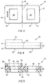
- FIG. 2 shows a top view of a photographic mount in accordance with the present invention;
- FIG. 3 shows a bottom view of the photographic mount of FIG. 2;
- FIG. 4 shows a side view of the photographic mount of FIG. 2;
- FIG. 5 shows a cross sectional view of the photographic mount of FIG. 2 taken along axis V-V; and
- FIG. 6 shows an inside perspective view of the photographic mount of FIG. 2 with the mount partially folded along the fold line.
-
- The following is a detailed description of the preferred embodiments of the invention, reference being made to the drawings in which the same reference numerals identify the same elements of structure in each of the several figures.
- Figures 2 through 6 illustrate a
photographic mount 30 in accordance with the present invention which is suitable for mounting a transparency. Mount 30 includes abase member 32 elongated in one direction along anaxis 34.Base member 32 includes afold line 36 disposed along anaxis 35 substantially perpendicular toaxis 34 to define a pair ofblanks -
Base member 32 is comprised of asupport layer 42 and apolymer layer 44 disposed thereon, as best illustrated in Figure 4.Support layer 42 may be comprised of a sufficiently rigid material to support a transparency such as cardboard, paperboard, metal, or glass. Preferably,support layer 42 is an inexpensive material to provide a reduction in the overall cost ofphotographic mount 30. In addition,support layer 42 preferably provides an exterior surface on which information can be provided (such as through writing or embossing), as best illustrated in Figure 3, for example to provide the name ("KODAK") of the manufacturer of the transparency. - A polymer layer 44 (or polymer coating) is disposed on one side of
support layer 42 by means known to those skilled in the art, for example, extruded coated.Polymer layer 44 is preferably a polyethylene, and more particularly, a low density polyethylene. Asuitable polymer layer 44 has a thickness in the range of 0.0005 to 0.003 inches, is susceptible to a heat range of 325-250 degrees F for at least a 0.3-0.5 second heat application dwell. Further,polymer layer 44 is preferably stable to 50 degrees C whenmount 30 is positioned within a cooperating operational projector for viewing the transparency.Polymer layer 44 provides a means of securing/holding the transparency during the mounting process, and also provides a permanent sealant for the photographic mount. -
Polymer layer 44 may comprise a color. That is,polymer layer 44 can be obtained in several solid colors. The coloring of the polymer layer negates the need for the custom coating on the interior surface of the board that prevents light transmission (i.e., a colored board), and thereby provides for the use of a commodity-produced white board assupport layer 42. Acolored polymer layer 44 may produce an opacifying effect of at least 2.5 ODU (optical density units). - An
aperture blanks Apertures base member 32 is folded alongfold line 36. - A locating
frame 50 is carried by one 38 of the pair of blanks to form a frame about one 46 of the pair of apertures to provide a means for correctly locating a transparency (not shown) and permitting the transparency to be more readily inserted. Locatingframe 50 is attached topolymer layer 44 of blank 38, and is so configured to define atransparency receiving area 52 onbase member 32 for receiving the transparency. Locatingframe 50 may be comprised of kraft paper, paper, or paperboard. Preferably, locatingframe 50 is a material which does not adversely affect the photographic characteristics of the transparency and is preferably an inexpensive material to provide a reduction in the overall cost ofphotographic mount 30. Locatingframe 50 may be applied to blank 38 by means known to those skilled in the art, for example, by the application of heat. - A coated strip or stripe of adhesive 53 may optionally be disposed on blank 38 within transparency receiving area 52 (preferably adjacent locating frame 50), as best illustrated in Figure 6. Such a strip of adhesive could provide for the attachment/aligning of the transparency to the mount when the mount is in an unfolded position. Strip of adhesive 53 could be, for example, a solvent based, thinly coated adhesive.
-
Blank 40 preferably includes a raised or embossedarea 54 disposed aboutaperture 48, as illustrated in Figure 6.Embossed area 54 is configured to correspond withtransparency receiving area 52, such that whenbase member 32 is folded alongfold line 36 andblanks area 54 overlaps and is disposed withintransparency receiving area 52 so as to secure the transparency in a substantially flat arrangement withintransparency receiving area 52. - To position the transparency within
mount 30, the transparency is disposed withintransparency receiving area 52 defined by locatingframe 50.Base member 32 is folded alongfold line 36, as best illustrated in Figure 6, wherebyapertures fold ling 36,polymer layer 44 disposed on blank 40abuts locating frame 50 disposed on blank 38. Heat is applied to mount 30 by means known to those skilled in the art.Polymer layer 44 is activated by the applied heat to thereby form a bond between locatingframe 50 andpolymer layer 44 disposed on blank 40, thereby sealing blank 38 to blank 40. Sincepolymer layer 44 is disposed directly onsupport layer 42, heat transmitted directly throughsupport layer 42 by a suitable heating element will seal the mount together. - Photographic mounts are typically stacked together in a shipping carton with a series of mounts stacked next to the other. The adhesive layer of the prior art mounts is sometimes tacky, and therefore, causes product loss due to the mounts becoming stuck together. In contrast, in the present invention,
polymer layer 44 is generally not tacky in ambient temperature, and therefore, the mounts generally do not stick together. - The polymer layer of the mount is a low density polyethylene having a thickness in the range of about 0.0005 to about 0.003 inches
- The polymer layer of the mount is susceptible to heat.
- The polymer layer of the mount forms a seal with the locating frame when the base member is folded along the fold line and the mount is heated.
- The mount comprises a strip of adhesive disposed on one of the pair of blanks inboard of the locating frame.
Claims (10)
- A mount for a transparency, comprising:a base member elongated in one direction along an axis, the base member having a fold line perpendicular to the axis to define a pair of blanks, the base member comprised of a support layer having a polymer layer disposed thereon;an aperture disposed in each of the pair of blanks, the apertures disposed in overlapping registration when the base member is folded along the fold line; anda frame adapted to locate the transparency, the frame disposed on one of the pair of blanks adjacent the polymer layer, the base member being foldable along the fold line wherein the frame abuts the polymer layer disposed on the other of the pair of blanks.
- The mount according to Claim 1 wherein the polymer layer is comprised of polyethylene.
- The mount according to Claim 2 wherein the polymer layer is comprised of a low density polyethylene.
- The mount according to Claim 3 wherein the polymer layer is a low density polyethylene having a thickness in the range of 0.0005 to 0.003 inches
- The mount according to Claim 1 wherein the polymer layer is susceptible to heat.
- The mount according to Claim 1 wherein the polymer layer forms a seal with the frame when the base member is folded along the fold line and the mount is heated.
- The mount according to Claim 1 further comprising a strip of adhesive disposed on one of the pair of blanks adjacent the frame.
- A photographic mount, comprising:a base member elongated in one direction along an axis, the base member having a fold line perpendicular to the axis to define a pair of blanks, the base member comprised of a support layer and a polymer layer;pair of spaced apertures, one of the pair of apertures disposed in each of the pair of blanks, the pair of apertures disposed in overlapping registration when the base member is folded along the fold line; anda locating frame carried by one of the pair of blanks to form a frame about one of the pair of apertures, the frame being attached to the polymer layer.
- The mount according to Claim 8 wherein the polymer layer is comprised of polyethylene.
- The mount according to Claim 9 wherein the polymer layer is comprised of a low density polyethylene.
Applications Claiming Priority (2)
| Application Number | Priority Date | Filing Date | Title |
|---|---|---|---|
| US458628 | 1983-01-17 | ||
| US09/458,628 US6502342B1 (en) | 1999-12-10 | 1999-12-10 | Photographic mount |
Publications (1)
| Publication Number | Publication Date |
|---|---|
| EP1111446A1 true EP1111446A1 (en) | 2001-06-27 |
Family
ID=23821511
Family Applications (1)
| Application Number | Title | Priority Date | Filing Date |
|---|---|---|---|
| EP00204237A Withdrawn EP1111446A1 (en) | 1999-12-10 | 2000-11-29 | Photographic slide holder |
Country Status (2)
| Country | Link |
|---|---|
| US (1) | US6502342B1 (en) |
| EP (1) | EP1111446A1 (en) |
Families Citing this family (2)
| Publication number | Priority date | Publication date | Assignee | Title |
|---|---|---|---|---|
| DE102004010448A1 (en) * | 2004-03-01 | 2005-09-22 | Clariant Gmbh | Use of a pigment composition with mixed crystals based on C.I. Pigment Yellow 74 |
| US20070228044A1 (en) * | 2006-03-15 | 2007-10-04 | Tony Rago | Protective cover for beverage |
Citations (4)
| Publication number | Priority date | Publication date | Assignee | Title |
|---|---|---|---|---|
| US3242605A (en) * | 1962-07-06 | 1966-03-29 | Seary Michelbach G M B H | Transparency mount |
| US3681866A (en) * | 1970-01-30 | 1972-08-08 | Johannes Loersch | Mounts for slide transparencies |
| US3718471A (en) * | 1970-08-03 | 1973-02-27 | Eastman Kodak Co | Film record card |
| US5459538A (en) * | 1993-04-07 | 1995-10-17 | Byers Industries, Inc. | Photo mounting equipment |
Family Cites Families (14)
| Publication number | Priority date | Publication date | Assignee | Title |
|---|---|---|---|---|
| US2291173A (en) * | 1941-08-05 | 1942-07-28 | Joseph L Simpson | Multiple picture projection slide |
| US2842883A (en) | 1956-05-10 | 1958-07-15 | Eastman Kodak Co | Paper mount for transparencies |
| US3077688A (en) * | 1959-08-06 | 1963-02-19 | Friedman Leonard | Photographic mount |
| US3235991A (en) * | 1965-03-29 | 1966-02-22 | Eastman Kodak Co | Paper mount for photographic transparencies |
| GB1256230A (en) * | 1968-05-28 | 1971-12-08 | Bertram Edward Charles Green | Improvements in mountings for photographic transparencies |
| US3814518A (en) * | 1973-02-20 | 1974-06-04 | R Wichers | Film-mount assembly |
| US4249328A (en) * | 1979-07-02 | 1981-02-10 | Photon Chroma, Inc. | Electrophotographic slide and method of making same |
| US4841652A (en) * | 1986-02-26 | 1989-06-27 | Efuesukei Kabushiki Kaisha | Adhesive sheet |
| US5234886A (en) * | 1991-06-28 | 1993-08-10 | Eastman Kodak Company | Thermal dye transfer receiver slide element |
| US5371560A (en) * | 1991-11-15 | 1994-12-06 | Minnesota Mining And Manufacturing Company | Envelope for transparency |
| SE501326C2 (en) * | 1992-10-14 | 1995-01-16 | Plastus Kreativ Ab | Storage and display pocket for overhead images |
| US5335027A (en) * | 1993-07-28 | 1994-08-02 | Lin Fong Ing | Transparency folder |
| US5322723A (en) * | 1993-08-09 | 1994-06-21 | Bickett Earl H | Tamperproof transparency mount with tear strip |
| US5905099A (en) * | 1995-11-06 | 1999-05-18 | Minnesota Mining And Manufacturing Company | Heat-activatable adhesive composition |
-
1999
- 1999-12-10 US US09/458,628 patent/US6502342B1/en not_active Expired - Fee Related
-
2000
- 2000-11-29 EP EP00204237A patent/EP1111446A1/en not_active Withdrawn
Patent Citations (4)
| Publication number | Priority date | Publication date | Assignee | Title |
|---|---|---|---|---|
| US3242605A (en) * | 1962-07-06 | 1966-03-29 | Seary Michelbach G M B H | Transparency mount |
| US3681866A (en) * | 1970-01-30 | 1972-08-08 | Johannes Loersch | Mounts for slide transparencies |
| US3718471A (en) * | 1970-08-03 | 1973-02-27 | Eastman Kodak Co | Film record card |
| US5459538A (en) * | 1993-04-07 | 1995-10-17 | Byers Industries, Inc. | Photo mounting equipment |
Also Published As
| Publication number | Publication date |
|---|---|
| US6502342B1 (en) | 2003-01-07 |
Similar Documents
| Publication | Publication Date | Title |
|---|---|---|
| US4870766A (en) | Picture support | |
| US4141162A (en) | Holder for photographs and the like | |
| US4964563A (en) | Covering foils for windows and packing boxes provided with such windows | |
| GB2281413A (en) | A photographic reflector | |
| CA2107728A1 (en) | Clear window label | |
| US1943022A (en) | Mount for pictures, photographs, and the like | |
| US4716672A (en) | Ornamental body | |
| US6401376B2 (en) | Frame type photograph mounting assembly | |
| US2842883A (en) | Paper mount for transparencies | |
| EP0755333B1 (en) | Slide blank | |
| US6502342B1 (en) | Photographic mount | |
| US3553866A (en) | Filmstrip viewing box | |
| EP1055525A2 (en) | Unidirectionally visible printed member | |
| US4660931A (en) | Foldable stereo viewer | |
| US5944186A (en) | Roll-like photosensitive material packing body | |
| JP2006315376A (en) | Photo album and its manufacturing method | |
| US1968674A (en) | Transparent mounting device | |
| US4152048A (en) | Stereoscopic viewer | |
| US5622420A (en) | Storage and projection pocket for overhead transparencies | |
| GB2283701A (en) | An applied film to prevent copying of a document. | |
| JP3666651B2 (en) | Packaging container for annular fluorescent lamp | |
| US2686986A (en) | Mount for transparencies | |
| JPH1195377A (en) | Roll film and its production | |
| WO1993021023A1 (en) | Article intended to the making of a customized postcard | |
| JP2913291B1 (en) | APS film envelope |
Legal Events
| Date | Code | Title | Description |
|---|---|---|---|
| PUAI | Public reference made under article 153(3) epc to a published international application that has entered the european phase |
Free format text: ORIGINAL CODE: 0009012 |
|
| AK | Designated contracting states |
Kind code of ref document: A1 Designated state(s): DE FR GB NL |
|
| AX | Request for extension of the european patent |
Free format text: AL;LT;LV;MK;RO;SI |
|
| 17P | Request for examination filed |
Effective date: 20011126 |
|
| AKX | Designation fees paid |
Free format text: DE FR GB NL |
|
| 17Q | First examination report despatched |
Effective date: 20040707 |
|
| STAA | Information on the status of an ep patent application or granted ep patent |
Free format text: STATUS: THE APPLICATION IS DEEMED TO BE WITHDRAWN |
|
| 18D | Application deemed to be withdrawn |
Effective date: 20041118 |