EP1111399B1 - Method and apparatus for measuring the state-of-charge of a battery - Google Patents
Method and apparatus for measuring the state-of-charge of a battery Download PDFInfo
- Publication number
- EP1111399B1 EP1111399B1 EP00310495A EP00310495A EP1111399B1 EP 1111399 B1 EP1111399 B1 EP 1111399B1 EP 00310495 A EP00310495 A EP 00310495A EP 00310495 A EP00310495 A EP 00310495A EP 1111399 B1 EP1111399 B1 EP 1111399B1
- Authority
- EP
- European Patent Office
- Prior art keywords
- battery
- charge
- time
- electrical
- current
- Prior art date
- Legal status (The legal status is an assumption and is not a legal conclusion. Google has not performed a legal analysis and makes no representation as to the accuracy of the status listed.)
- Expired - Lifetime
Links
- 238000000034 method Methods 0.000 title claims description 13
- 239000003990 capacitor Substances 0.000 claims description 59
- 238000005259 measurement Methods 0.000 claims description 22
- 238000007599 discharging Methods 0.000 claims description 8
- 238000004364 calculation method Methods 0.000 description 4
- 230000000712 assembly Effects 0.000 description 2
- 238000000429 assembly Methods 0.000 description 2
- 238000013213 extrapolation Methods 0.000 description 2
- 230000002776 aggregation Effects 0.000 description 1
- 238000004220 aggregation Methods 0.000 description 1
- 238000006243 chemical reaction Methods 0.000 description 1
- 230000008878 coupling Effects 0.000 description 1
- 238000010168 coupling process Methods 0.000 description 1
- 238000005859 coupling reaction Methods 0.000 description 1
- 230000001419 dependent effect Effects 0.000 description 1
- 230000000779 depleting effect Effects 0.000 description 1
- 238000010586 diagram Methods 0.000 description 1
- 238000010438 heat treatment Methods 0.000 description 1
- 239000004973 liquid crystal related substance Substances 0.000 description 1
- 210000000352 storage cell Anatomy 0.000 description 1
Images
Classifications
-
- G—PHYSICS
- G01—MEASURING; TESTING
- G01R—MEASURING ELECTRIC VARIABLES; MEASURING MAGNETIC VARIABLES
- G01R31/00—Arrangements for testing electric properties; Arrangements for locating electric faults; Arrangements for electrical testing characterised by what is being tested not provided for elsewhere
- G01R31/36—Arrangements for testing, measuring or monitoring the electrical condition of accumulators or electric batteries, e.g. capacity or state of charge [SoC]
- G01R31/3644—Constructional arrangements
- G01R31/3648—Constructional arrangements comprising digital calculation means, e.g. for performing an algorithm
-
- G—PHYSICS
- G01—MEASURING; TESTING
- G01R—MEASURING ELECTRIC VARIABLES; MEASURING MAGNETIC VARIABLES
- G01R31/00—Arrangements for testing electric properties; Arrangements for locating electric faults; Arrangements for electrical testing characterised by what is being tested not provided for elsewhere
- G01R31/36—Arrangements for testing, measuring or monitoring the electrical condition of accumulators or electric batteries, e.g. capacity or state of charge [SoC]
- G01R31/382—Arrangements for monitoring battery or accumulator variables, e.g. SoC
- G01R31/3828—Arrangements for monitoring battery or accumulator variables, e.g. SoC using current integration
-
- G—PHYSICS
- G01—MEASURING; TESTING
- G01R—MEASURING ELECTRIC VARIABLES; MEASURING MAGNETIC VARIABLES
- G01R31/00—Arrangements for testing electric properties; Arrangements for locating electric faults; Arrangements for electrical testing characterised by what is being tested not provided for elsewhere
- G01R31/005—Testing of electric installations on transport means
- G01R31/006—Testing of electric installations on transport means on road vehicles, e.g. automobiles or trucks
Definitions
- This invention relates to a method and to an apparatus for measuring the state-of-charge of a battery and more particularly, to a method and to an apparatus for accurately measuring the state-of-charge of a vehicle battery.
- Batteries are used in many assemblies, such as in vehicles, to provide electrical power to the various components and/or devices which co-operatively and respectively form these assemblies. It is highly desirable to accurately and continually measure and/or ascertain the electrical charge remaining within the battery, commonly referred to as the "state-of-charge", in order to ensure that the battery is timely and efficiently recharged or replaced, and to further ensure continued and substantially uninterrupted operation of the vehicle or other type of "battery powered” assembly. Consequently, many devices have been developed and have been used to selectively measure the state-of-charge of a battery and to selectively display the measured state-of-charge to a user of the battery powered assembly.
- prior state-of-charge measuring devices typically include an electrical current integrator (e.g., a capacitor) which is connected to the battery in an "electrical series” arrangement or manner, and which operatively integrates the electrical current which is provided by the battery. Particularly, this electrical current is coupled to and made to traverse the device.
- the device calculates the amount of electrical charge which has passed into the device due to the received electrical current. Particularly, this calculation is accomplished by measuring the voltage and/or the charge of the capacitor (i.e., the integral of the electrical current which has been received by the device during a certain time interval is substantially equal to the electrical charge on the contained capacitor during this time interval).
- this device measures the amount of electrical charge which is provided to the battery and the summation of these charges (i.e., the charges respectively provided by and provided to the battery) provides an accurate indication of the current state-of-charge of the battery.
- capacitors employed by these prior devices effectively and respectively integrate the electrical current flowing into and/or out of the battery over a discrete interval of time
- the capacitors eventually reach their respective charge storing capacity limit and must be "reset” or electrically discharged before continuing to integrate or further accumulate any more electrical charge. Discharging these capacitors requires some finite period of time, which is usually dependent upon the size of the capacitor.
- Patent Abstracts of Japan, vol. 016, no. 460, (P-1427) &JP 04 164269 A describes apparatus intended for use in combination with a battery and comprising three portions.
- the first and second portions are selectively and electrically dischargeable portions coupled to the battery.
- the third portion operates on the results coming from the first and second portions in order to provide information to determine the electrical charge of the battery.
- an apparatus for use in combination with a battery having an electrical charge comprising:
- a method for determining the amount of charge remaining within a battery comprising the steps of:
- a method and an apparatus embodying the present invention overcomes some or all of the previously delineated drawbacks associated with prior battery state-of-charge measuring devices. It selectively and continuously measures the amount of charge flowing into and out of the battery. Further it is substantially and automatically self-calibrating.
- apparatus 10 for measuring the state-of-charge of a battery and which is made in accordance with the teachings of the preferred embodiment of the invention.
- apparatus 10 is connected in "electrical series” with a conventional and/or typical storage cell or battery 14 and to a variable load 16.
- Battery 14, variable load 16 and apparatus 10 therefore, as shown co-operatively form an "electrical series type" circuit 12.
- variable load 16 includes and functionally represents both electrical discharging/depleting components (e.g., components which remove electrical current or electrical charge from battery 14), such as an electric motor, electric lights, and/or heating elements, as well as electrical recharging/supplying components (e.g., components which replace or transfer electrical current or electrical charge into battery 14), such as an alternator and/or battery charger.
- electrical discharging/depleting components e.g., components which remove electrical current or electrical charge from battery 14
- electrical recharging/supplying components e.g., components which replace or transfer electrical current or electrical charge into battery 14
- alternator and/or battery charger the electrical current which selectively travels through circuit 12 flows in the direction 13 (e.g., into the battery 14) or in the direction 15 (e.g., out of battery 14).
- battery 14 comprises and/or represents the battery of an electric vehicle and variable load 16 comprises and/or represents the electrical components of a conventional and/or commercially available vehicle (e.g., an electric vehicle) which are physically and electrically connected to battery 14 and which selectively remove electrical charge from or which selectively provide electrical charge to battery 14.
- a conventional and/or commercially available vehicle e.g., an electric vehicle
- Apparatus 10 includes a conventional sensing or "shunt" resistor 18 having a relatively small resistance value and which is connected in “electrical series” with battery 14 and load 16. By continually and/or systematically measuring the varying voltage "across" resistor 18, apparatus 10 calculates the amount or the value of the electrical charge passing into and/or out of battery 14. As described more fully and completely below, apparatus 10 aggregates (e.g., keeps a running total of) these calculated values and uses this aggregation to derive and/or to substantially and accurately ascertain the state-of-charge of the battery 14.
- apparatus 10 determines the amount of the electrical charge remaining within battery 14 or the "current state-of-charge" of the battery 14.
- Apparatus 10 includes a variable voltage sensing and current generating assembly or portion 22, which is physically connected in a electrical "parallel manner" to resistor 18.
- Assembly or device 22 includes two substantially identical and conventional gated variable current sources 24, 26.
- Device 22 is adapted to sense the voltage across resistor 18, (e.g., denoted as “ V(t) "), and to selectively cause each of current sources 24, 26 to generate electrical currents, respectively denoted as “ I' 1 (t) " and “ I' 2 (t) “, which are each proportional to the voltage, " V(t) ", “across” resistor 18.
- I' 1 (t) kV(t) when gate 28 is “true” or open
- I' 1 (t) 0 when gate 28 is “false” or closed
- I' 2 (t) kV(t) when gate 30 is “true” or open
- I' 2 (t) 0 when gate 30 is “false” or closed
- Apparatus 10 further includes a conventional and/or commercially available microprocessor, microcontroller, or controller 20 operating under stored program control.
- Controller 20 includes a conventional memory unit or portion 36 and two conventional and commercially available analogue-to-digital conversion devices 38, 40, which are adapted to selectively receive and to convert the measured analogue voltage to a digital value.
- the program defining the operations of controller 20 is selectively stored within memory 36.
- Controller 20 is coupled to gates 28, 30 by use of control lines or busses 32, 34. Controller 20 is further coupled to switches 42, 44, which comprise conventional and commercially available electronic or electromechanical switching devices (e.g., transistors or relays), by respective use of control lines or busses 46, 48. In other alternate embodiments, switches 42, 44 may comprise a single switching device or chip. Switches 42 and 44, operating under control of controller 20, have respective terminals 55, 61 which are respectively and selectively coupled to a selected one of the terminals 50, 52, 54 and to a selected one of the terminals 56, 58, 60.
- switches 42, 44 which comprise conventional and commercially available electronic or electromechanical switching devices (e.g., transistors or relays), by respective use of control lines or busses 46, 48. In other alternate embodiments, switches 42, 44 may comprise a single switching device or chip. Switches 42 and 44, operating under control of controller 20, have respective terminals 55, 61 which are respectively and selectively coupled to a selected one of the terminals 50, 52, 54
- Terminals 50, 56 are each coupled to a conventional and constant or "calibrated" current source 62 by use of bus 63; terminals 52, 58 are each coupled to electrical ground portion 70 by use of bus 59; and terminals 54, 60 are electrically "open” or unconnected terminals.
- Controller 20 is further coupled, by bus 69, to a display 68 comprising, a conventional and commercially available output display device, such as and without limitation a flat panel display, a liquid crystal display, an analogue gauge display, a video display, or substantially any other type of display which is suitable to display output data and/or information which is generated by the controller.
- display 68 is mounted within the passenger compartment of a vehicle, such as on or within the vehicle dashboard or instrument panel (not shown).
- a pair of conventional electrical current integrators or capacitors 64, 66 which, in the preferred embodiment of the invention, comprise substantially identical, conventional, and commercially available capacitors, are connected to terminals 55, 61 of switches 42, 44 and to gated variable current sources 24, 26 by respective busses 71, 73, to analogue-to-digital converters 38, 40, by respective busses 35, 37, and to the electrical ground or the electrical "zero" potential 70.
- apparatus 10 measures the voltage "across" resistor 18 (e.g., denoted as " V(t) "). This voltage is substantially equal to the value of the current " I(t) " multiplied by the value of " R s ", where " R s " represents and/or denotes the electrical resistance value of resistor 18. Further, after device 22 senses or measures the voltage " V(t) ", the device 22 generates the previously described currents " I' 1 (t) " and “ I' 2 (t) " by use of the electrical current sources 24, 26 in the following manner.
- controller 20 selectively switches on gate 28 by placing an electrical signal onto bus 32 and substantially and simultaneously “toggles” or places switch 42 in a “measure position” by coupling terminal 55 to terminal 54.
- capacitor 64 receives the current " I' 1 (t) " by or through bus 71.
- V 1 1 C 1 ⁇ I ⁇ 1 t d t
- V 1 denotes the voltage which is created “across” capacitor 64 by the received electrical current
- C 1 denotes the capacitance of capacitor 64
- I' 1 (t) denotes the electrical current flowing from source 24 into the capacitor 64
- Q 1 ⁇ I ⁇ 1 t d t
- Q 1 denotes the amount of electrical charge received by capacitor 64 during an interval of time (i.e., integrating " I' 1 (t)dt " provides the amount of electrical charge received by the capacitor 64 during the interval of time for which the integral is evaluated).
- controller 20 determines this amount of electrical charge, " Q 1 ", received by the capacitor 64 by measuring the voltage “across” the capacitor 64, " V 1 ", after a certain or predetermined interval of time has elapsed (the initial voltage across capacitor 64 is assumed to be zero in this non-limiting example) and multiplying that voltage by the value of " C 1 ".
- controller 20 switches off gate 28 and simultaneously and operatively activates portion 38 which measures the voltage, " V 1 ", "across” capacitor 64.
- Device 38 then digitises the measured voltage “ V 1 " (i.e., converts voltage " V 1 " to a digital number), and stores this value within memory 36.
- controller 20 switches off gate 28 to perform the aforedescribed measurement
- controller 20 by use of control bus or line 34, substantially and simultaneously switches on gate 30 and "toggles" switch 44 to a measure position by connecting terminal 61 to terminal 60 (i.e., the "measure” position), thereby allowing apparatus 10 to continue to measure substantially all of the electrical current flowing through resistor 18 and which is provided to or provided by battery 16, without delay or interruption.
- source 26 by switching on gate 30, source 26 generates current " I' 2 (t) ,” which is received and which is "integrated” by capacitor 66, according to the above-described procedure.
- Device 40 digitises the voltage upon capacitor 66, "V 2 " and the resulting “digitised” capacitor voltage “ V 2 " is multiplied by the value of " C 2 " to determine the amount of accumulated charge " Q 2 " (i.e., V 2 * C 2 ) over the interval of time that gate 30 is switched to supply current.
- While capacitor 66 "integrates” current “ I' 2 (t) ", apparatus 10 discharges capacitor 64. More particularly, as gate 28 is switched off (and gate 30 is switched on), controller 20 simultaneously “toggles” or moves switch 42 to terminal 52, by use of bus 46, thereby connecting capacitor 64 to electrical ground 70 and causing capacitor 64 to begin to electrically discharge. After a predetermined period of time has elapsed and capacitor 64 is substantially and completely discharged (e.g., after about one millisecond), controller 20, by use of control line or bus 46, moves switch 42 to terminal 50, thereby connecting capacitor 64 to the constant calibrated current source 62.
- Capacitor 64 remains electrically “grounded” until the capacitor 66 has been fully charged. Controller 20 then simultaneously switches off gate 30 while switching on gate 28; and substantially and simultaneously connects terminal 55 to "measurement” terminal 54 while connecting terminal 61 to “discharge” terminal 58. Capacitor 64 again integrates the generated current " I' 1 (t) " in the previously described manner, thereby calculating a second " Q 1 " value which is stored within memory 36 and which is added to the value of " Q total ". As the charge “ Q 1 " is calculated, capacitor 66 is initially electrically discharged, “calibrated” and again electrically discharged in a substantially identical manner and sequence, as previously described for capacitor 64.
- controller 20 selectively calculates a second " Q 2 " measurement, while discharging, calibrating, and discharging capacitor 64 in the same previously described manner and sequence.
- the total value of the electrical charge passing through capacitors 64, 66, during any one period of time or "cycle” in which a pair of " Q 1 " and " Q 2 " measurements are made is related to the total charge "Q" passing in and/or out of battery 14 during that same interval of time or "cycle”.
- Controller 20 utilises the following equations to determine this charge for any one such "cycle”:
- Q 1 R s ⁇ k ⁇ ⁇ I ⁇ 1 t d t + ⁇ I ⁇ 2 t d t or
- Q Q 1 + Q 2 R s ⁇ k
- Controller 20 utilises the above-described relationships to keep a "running total” or “tally” of the amount of charge, " Q(t) ", which has passed out of or into battery 14 over time.
- the value of " Q(t) " e.g., the total amount of the charge which has been provided by or to the battery
- Q total the total amount of measured charge
- R s k the total amount of measured charge
- controller 20 maintains and selectively updates the value "Q(t)", representing the "running total” of the amount of charge which has passed out of battery 14 (e.g., having a positive value) or has passed into battery 14 (e.g., having a negative value).
- controller 20 dynamically determines the current state-of-charge of battery 14 or the charge remaining in battery 14. Controller 20 continuously outputs this current "state-of-charge” value to display 68, so that a user of apparatus 10 has a continuous and current display of the electrical charge remaining within battery 14.
Landscapes
- Physics & Mathematics (AREA)
- General Physics & Mathematics (AREA)
- Secondary Cells (AREA)
- Charge And Discharge Circuits For Batteries Or The Like (AREA)
Description
- This invention relates to a method and to an apparatus for measuring the state-of-charge of a battery and more particularly, to a method and to an apparatus for accurately measuring the state-of-charge of a vehicle battery.
- Batteries are used in many assemblies, such as in vehicles, to provide electrical power to the various components and/or devices which co-operatively and respectively form these assemblies. It is highly desirable to accurately and continually measure and/or ascertain the electrical charge remaining within the battery, commonly referred to as the "state-of-charge", in order to ensure that the battery is timely and efficiently recharged or replaced, and to further ensure continued and substantially uninterrupted operation of the vehicle or other type of "battery powered" assembly. Consequently, many devices have been developed and have been used to selectively measure the state-of-charge of a battery and to selectively display the measured state-of-charge to a user of the battery powered assembly.
- These prior state-of-charge measuring devices typically include an electrical current integrator (e.g., a capacitor) which is connected to the battery in an "electrical series" arrangement or manner, and which operatively integrates the electrical current which is provided by the battery. Particularly, this electrical current is coupled to and made to traverse the device. The device, in this manner, calculates the amount of electrical charge which has passed into the device due to the received electrical current. Particularly, this calculation is accomplished by measuring the voltage and/or the charge of the capacitor (i.e., the integral of the electrical current which has been received by the device during a certain time interval is substantially equal to the electrical charge on the contained capacitor during this time interval). Similarly, this device measures the amount of electrical charge which is provided to the battery and the summation of these charges (i.e., the charges respectively provided by and provided to the battery) provides an accurate indication of the current state-of-charge of the battery.
- As noted, many of these prior devices perform these calculations by measuring the voltage which is applied to and/or which is received by the capacitor from the battery, after a certain interval of time has elapsed, by the use of the equation: Q=V*C, where "Q" equals the amount of electrical charge accumulated by the capacitor or the integral of the electrical current which passes into the capacitor during the interval of time, "V" equals the voltage across the capacitor at the end of the interval of time, and "C" equals the capacitance value of the capacitor. In order for the foregoing calculation to be accurate, there must be substantially no voltage across the capacitor at the beginning of each measured time interval. Moreover, these calculations and/or measurements should be initiated as soon as the fully charged battery is operatively placed into the assembly.
- These prior devices typically "conduct" or make these measurements over consecutive intervals of time and add these measurements together to determine the total electrical charge which has passed into and/or out of the battery. That is, by subtracting the total electrical charge which has passed out of the battery from the battery's total electrical charge capacity and then by adding the total electrical charge which has passed into the battery, a relatively accurate and current estimate is provided of the battery's remaining charge. A "running total" of the electrical charge remaining in the battery or the battery's "state-of-charge" is typically stored within the memory of these devices and is selectively displayed to a user of the vehicle or other battery powered device. While these state-of-charge measuring devices do effectively maintain and display the state-of-charge of a battery, they suffer from some drawbacks which undesirably reduce their respective accuracy.
- For example and without limitation, while the capacitors employed by these prior devices effectively and respectively integrate the electrical current flowing into and/or out of the battery over a discrete interval of time, the capacitors eventually reach their respective charge storing capacity limit and must be "reset" or electrically discharged before continuing to integrate or further accumulate any more electrical charge. Discharging these capacitors requires some finite period of time, which is usually dependent upon the size of the capacitor.
- While these capacitors are being discharged, the battery continues to operate (i.e., continues to provide and/or receive electrical current) and the concomitant change in the state-of-charge of the battery is not detected or measured by these devices (i.e., these devices are inoperable). Thus, this "unmeasured electrical current" is not factored into the "running total" kept by these devices, thereby causing these devices to produce inaccurate and/or erroneous "state-of-charge" estimates.
- Attempts have been made to mathematically estimate the "unmeasured electrical current" using conventional mathematical extrapolation techniques. While these extrapolation techniques have been shown to somewhat reduce the overall error, they are not highly accurate and often result in the creation of relatively small errors which accumulate over time, causing the creation of relatively large undesirable state-of-charge measurement errors. These techniques further add undesirable complexity to these prior state-of-charge devices.
- Additionally, the capacitance values of these capacitors often drift or vary over time. Any uncompensated variance in these capacitance values will cause these prior devices to further provide inaccurate state-of-charge measurements. In order to correct for these variances, efforts have been made to calibrate these devices and/or to measure the value of these capacitors at regular and/or discrete intervals of time, and to thereafter selectively compensate for the measured variances. However, while these devices are being calibrated, no measurement is made of the electrical current flowing into and out of the battery, thereby further increasing the state-of-charge measurement error.
- There is therefore a need for a new and improved state-of-charge measuring device which provides a relatively accurate measure of the state-of-charge of a battery; which continuously measures or integrates the electrical current passing into or out of a battery; and which continues to integrate and/or measure electrical current while the device is being reset, discharged, and/or calibrated.
- Patent Abstracts of Japan, vol. 016, no. 460, (P-1427) &JP 04 164269 A describes apparatus intended for use in combination with a battery and comprising three portions. The first and second portions are selectively and electrically dischargeable portions coupled to the battery. The third portion operates on the results coming from the first and second portions in order to provide information to determine the electrical charge of the battery.
- According to a first aspect of the present invention, there is provided an apparatus for use in combination with a battery having an electrical charge, said apparatus comprising:
- a first portion which is selectively coupled to said battery for a first period of time and which measures the said electrical charge of said battery during said first period of time, and which is selectively and electrically dischargeable;
- a second portion which is selectively coupled to said battery for a second period of time and which measures the said electrical charge of said battery during said second period of time, and which is selectively and electrically dischargeable;
- a third portion which is selectively coupled to said first portion during said second period of time and to said second portion during said first period of time and which electrically discharges and then calibrates said first portion during said second period of time and which electrically discharges and then calibrates said second portion during said first period of time, thereby allowing said first and second portions to co-operatively provide a measurement of said electrical charge of said battery.
- According to a second aspect of the present invention, there is provided a method for determining the amount of charge remaining within a battery, said method comprising the steps of:
- providing first and second selectively and electrically dischargeable current integrators;
- providing first and second current generators which respectively and selectively generate a first and a second electrical current;
- communicating said first electrical current to said first current integrator for a first interval of time, thereby producing a first voltage;
- communicating said second current to said second current integrator for a second interval of time, thereby producing a second voltage;
- selectively discharging and then calibrating said first current integrator during said second interval of time;
- selectively discharging and then calibrating said second current integrator during said first interval of time; and
- using said first and second voltages to determine the amount of charge remaining within said battery.
- A method and an apparatus embodying the present invention overcomes some or all of the previously delineated drawbacks associated with prior battery state-of-charge measuring devices. It selectively and continuously measures the amount of charge flowing into and out of the battery. Further it is substantially and automatically self-calibrating.
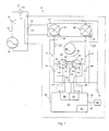
- The present invention will now be described further, by way of example, with reference to the accompanying drawing which is a block diagram of an apparatus for measuring the state-of-charge of a battery which is made in accordance with the teachings of the preferred embodiment of the invention.
- Referring now to the drawing, there is shown an
apparatus 10 for measuring the state-of-charge of a battery and which is made in accordance with the teachings of the preferred embodiment of the invention. Particularly,apparatus 10 is connected in "electrical series" with a conventional and/or typical storage cell orbattery 14 and to avariable load 16.Battery 14,variable load 16 andapparatus 10 therefore, as shown co-operatively form an "electrical series type"circuit 12. - In the preferred embodiment of the invention,
variable load 16 includes and functionally represents both electrical discharging/depleting components (e.g., components which remove electrical current or electrical charge from battery 14), such as an electric motor, electric lights, and/or heating elements, as well as electrical recharging/supplying components (e.g., components which replace or transfer electrical current or electrical charge into battery 14), such as an alternator and/or battery charger. Hence, the electrical current which selectively travels throughcircuit 12, denoted as "I(t)", flows in the direction 13 (e.g., into the battery 14) or in the direction 15 (e.g., out of battery 14). In one non-limiting example,battery 14 comprises and/or represents the battery of an electric vehicle andvariable load 16 comprises and/or represents the electrical components of a conventional and/or commercially available vehicle (e.g., an electric vehicle) which are physically and electrically connected tobattery 14 and which selectively remove electrical charge from or which selectively provide electrical charge tobattery 14. -
Apparatus 10 includes a conventional sensing or "shunt"resistor 18 having a relatively small resistance value and which is connected in "electrical series" withbattery 14 andload 16. By continually and/or systematically measuring the varying voltage "across"resistor 18,apparatus 10 calculates the amount or the value of the electrical charge passing into and/or out ofbattery 14. As described more fully and completely below,apparatus 10 aggregates (e.g., keeps a running total of) these calculated values and uses this aggregation to derive and/or to substantially and accurately ascertain the state-of-charge of thebattery 14. That is, by dynamically subtracting this total value of the electrical charge expelled bybattery 14 from the total charge capacity ofbattery 14, and adding the total value of the electrical charge which has been provided to thebattery 14,apparatus 10 determines the amount of the electrical charge remaining withinbattery 14 or the "current state-of-charge" of thebattery 14. -
Apparatus 10 includes a variable voltage sensing and current generating assembly orportion 22, which is physically connected in a electrical "parallel manner" toresistor 18. Assembly ordevice 22 includes two substantially identical and conventional gated variablecurrent sources Device 22 is adapted to sense the voltage acrossresistor 18, (e.g., denoted as "V(t)"), and to selectively cause each ofcurrent sources resistor 18. The electrical currents generated bysources gate 28 is "true" or open; I' 1 (t)=0 whengate 28 is "false" or closed, I' 2 (t)=kV(t) whengate 30 is "true" or open; and I' 2 (t)=0 whengate 30 is "false" or closed, where "k" is equal to a proportionality constant and where "t" denotes an instant of measured time. -
Apparatus 10 further includes a conventional and/or commercially available microprocessor, microcontroller, orcontroller 20 operating under stored program control.Controller 20 includes a conventional memory unit orportion 36 and two conventional and commercially available analogue-to-digital conversion devices controller 20 is selectively stored withinmemory 36. -
Controller 20 is coupled togates Controller 20 is further coupled toswitches Switches controller 20, haverespective terminals terminals terminals Terminals current source 62 by use ofbus 63;terminals electrical ground portion 70 by use ofbus 59; andterminals -
Controller 20 is further coupled, bybus 69, to adisplay 68 comprising, a conventional and commercially available output display device, such as and without limitation a flat panel display, a liquid crystal display, an analogue gauge display, a video display, or substantially any other type of display which is suitable to display output data and/or information which is generated by the controller. In the one non-limiting embodiment,display 68 is mounted within the passenger compartment of a vehicle, such as on or within the vehicle dashboard or instrument panel (not shown). - A pair of conventional electrical current integrators or
capacitors terminals switches current sources respective busses 71, 73, to analogue-to-digital converters respective busses - In operation,
apparatus 10 measures the voltage "across" resistor 18 (e.g., denoted as "V(t)"). This voltage is substantially equal to the value of the current "I(t)" multiplied by the value of "Rs ", where "Rs " represents and/or denotes the electrical resistance value ofresistor 18. Further, afterdevice 22 senses or measures the voltage "V(t)", thedevice 22 generates the previously described currents " I'1(t)" and " I' 2 (t)" by use of the electricalcurrent sources - Particularly, during an initial or first measurement cycle,
controller 20 selectively switches ongate 28 by placing an electrical signal ontobus 32 and substantially and simultaneously "toggles" or places switch 42 in a "measure position" by couplingterminal 55 toterminal 54. In this manner,capacitor 64 receives the current "I'1(t)" by or through bus 71. The following equations are used by thecontroller 20 to calculate the amount of electrical charge which is received by capacitor 64 :
capacitor 64 by the received electrical current, "C1 " denotes the capacitance ofcapacitor 64, and I'1(t) denotes the electrical current flowing fromsource 24 into thecapacitor 64; and
capacitor 64 during an interval of time (i.e., integrating "I'1(t)dt" provides the amount of electrical charge received by thecapacitor 64 during the interval of time for which the integral is evaluated). Substituting and solving for the value "∫I'1(t)dt" or "Q 1", yields the equation
- Utilising this third equation,
controller 20 determines this amount of electrical charge, "Q 1", received by thecapacitor 64 by measuring the voltage "across" thecapacitor 64, "V1 ", after a certain or predetermined interval of time has elapsed (the initial voltage acrosscapacitor 64 is assumed to be zero in this non-limiting example) and multiplying that voltage by the value of "C1 ". - Specifically, in the preferred embodiment of the invention, after a predetermined period of time has elapsed, (e.g., the end of the first measurement cycle),
controller 20 switches offgate 28 and simultaneously and operatively activatesportion 38 which measures the voltage, "V1 ", "across"capacitor 64.Device 38 then digitises the measured voltage "V1 " (i.e., converts voltage "V1 " to a digital number), and stores this value withinmemory 36. In the preferred embodiment, the digitised voltage value is further multiplied by the digitised value of "C1 ", and the resulting value, equalling the amount of charge received bycapacitor 64 during the measured interval of time (i.e., Q 1 = V1 * C1 ), is stored within thenon-volatile memory 36 ofcontroller 20. - As
controller 20 switches offgate 28 to perform the aforedescribed measurement,controller 20, by use of control bus orline 34, substantially and simultaneously switches ongate 30 and "toggles"switch 44 to a measure position by connectingterminal 61 to terminal 60 (i.e., the "measure" position), thereby allowingapparatus 10 to continue to measure substantially all of the electrical current flowing throughresistor 18 and which is provided to or provided bybattery 16, without delay or interruption. Specifically, by switching ongate 30,source 26 generates current "I'2(t)," which is received and which is "integrated" bycapacitor 66, according to the above-described procedure.Device 40 digitises the voltage uponcapacitor 66, "V 2 " and the resulting "digitised" capacitor voltage "V2 " is multiplied by the value of "C 2" to determine the amount of accumulated charge "Q 2" (i.e., V2 * C 2) over the interval of time thatgate 30 is switched to supply current. This charge "Q 2" is added to the previously stored charge value "Q 1", thereby providing a measurement of the total amount of charge, "Qtotal ," that has been received bycapacitors 64, 66 (e.g., Qtotal = Q 1 + Q 2) during these two measurement cycles. - While
capacitor 66 "integrates" current "I'2(t)",apparatus 10discharges capacitor 64. More particularly, asgate 28 is switched off (andgate 30 is switched on),controller 20 simultaneously "toggles" or moves switch 42 toterminal 52, by use ofbus 46, thereby connectingcapacitor 64 toelectrical ground 70 and causingcapacitor 64 to begin to electrically discharge. After a predetermined period of time has elapsed andcapacitor 64 is substantially and completely discharged (e.g., after about one millisecond),controller 20, by use of control line orbus 46, moves switch 42 toterminal 50, thereby connectingcapacitor 64 to the constant calibratedcurrent source 62. -
Current source 62 provides a constant electrical current to capacitor 64 over a predetermined period of time. After the predetermined period of time has expired,device 38 measures the voltage "across"capacitor 64, as previously described.Controller 20 mathematically "solves for" the current capacitance value, "C1 ," ofcapacitor 64 by use of the equation
where "Vcal " is the measured voltage "across"capacitor 64 and where "I'cal(t)" is the known calibration current emanating fromsource 62. - This measured capacitance value, "C1," is then used by
controller 20 in the subsequent measurement of charge "Q1 ". In this manner, it should be appreciated thatapparatus 10 automatically adjusts and/or corrects for any "drift" or variance in the capacitance value ofcapacitor 64 between each measurement cycle in whichcapacitor 64 is used to provide a charge measure. After the calibration measurement is made,controller 20 moves terminal 55 toterminal 52, thereby connectingcapacitor 64 to ground and effective toelectrically discharge capacitor 64. -
Capacitor 64 remains electrically "grounded" until thecapacitor 66 has been fully charged.Controller 20 then simultaneously switches offgate 30 while switching ongate 28; and substantially and simultaneously connects terminal 55 to "measurement"terminal 54 while connectingterminal 61 to "discharge"terminal 58.Capacitor 64 again integrates the generated current "I'1(t)" in the previously described manner, thereby calculating a second "Q 1" value which is stored withinmemory 36 and which is added to the value of "Qtotal ". As the charge "Q 1" is calculated,capacitor 66 is initially electrically discharged, "calibrated" and again electrically discharged in a substantially identical manner and sequence, as previously described forcapacitor 64. Once the second "Q 1" measurement is complete,controller 20 selectively calculates a second "Q 2" measurement, while discharging, calibrating, and dischargingcapacitor 64 in the same previously described manner and sequence.Apparatus 10 continues to repeat these procedures in this manner, thereby continually summing the integrated electrical currents or charge values "Q 1", "Q 2" over sequential intervals of time. In this manner,apparatus 10 dynamically creates and maintains a substantially accurate total value of the electrical charge "Qtota1 " passing throughcapacitors 64, 66 (i.e., Qtotal = Q 1 + Q 2 + Q 1 + Q 2 + ...). It should be appreciated that the "sign" (i.e., positive and negative) and value of the "Q 1 and "Q 2" measurements will vary depending on the direction and magnitude of current "I(t)" (e.g., charges entering thebattery 14 will have a "negative" magnitude and those leaving thebattery 14 will have a "positive" magnitude). - The total value of the electrical charge passing through
capacitors battery 14 during that same interval of time or "cycle".Controller 20 utilises the following equations to determine this charge for any one such "cycle":


-
Controller 20 utilises the above-described relationships to keep a "running total" or "tally" of the amount of charge, "Q(t)", which has passed out of or intobattery 14 over time. Particularly, the value of "Q(t)" (e.g., the total amount of the charge which has been provided by or to the battery) is equal to the total amount of measured charge "Qtotal " (i.e., Q 1 + Q 2 + Q 1 + Q 2 + .. .) divided by the quantity "Rsk". - As the value of "Qtotal " is accumulated the total electrical charge flowing out of or into
battery 14, "Q(t)" is simultaneously accumulated bycontroller 20 in the foregoing manner. Particularly,controller 20 maintains and selectively updates the value "Q(t)", representing the "running total" of the amount of charge which has passed out of battery 14 (e.g., having a positive value) or has passed into battery 14 (e.g., having a negative value). By subtracting the current value of Q(t) from the total charge capacity ofbattery 14,controller 20 dynamically determines the current state-of-charge ofbattery 14 or the charge remaining inbattery 14.Controller 20 continuously outputs this current "state-of-charge" value to display 68, so that a user ofapparatus 10 has a continuous and current display of the electrical charge remaining withinbattery 14.
Claims (9)
- An apparatus for use in combination with a battery (14) having an electrical charge, said apparatus comprising:a first portion (38,42,64) which is selectively coupled to said battery (14) for a first period of time and which measures the said electrical charge of said battery (14) during said first period of time, and which is selectively and electrically dischargeable;a second portion (40,44,66) which is selectively coupled to said battery (14) for a second period of time and which measures said electrical charge of said battery (14) during said second period of time, and which is selectively and electrically dischargeable;a third portion (62) which is selectively coupled to said first portion (38,42,64) during said second period of time and to said second portion (40,44,66) during said first period of time and which electrically discharges and then calibrates said first portion (38,42,64) during said second period of time and which electrically discharges and then calibrates said second portion (40,44,66) during said first period of time, thereby allowing said first and second portions to co-operatively provide a measurement of said electrical charge of said battery.
- An apparatus as claimed in claim 1 further comprising a controller (20) to calculate said electrical charge of said battery (14).
- An apparatus as claimed in claim 2, further comprising a display (68) which displays the state of charge of the said battery (14).
- An apparatus as claimed in claim 1, wherein said first and said second portions (38,40,42,44,64,66) each comprise an electrical current integrator (64,66).
- An apparatus as claimed in claim 1, wherein said first and said second portions (38,40,42,44,64,66) each comprise an electrical current integrator (64,66) in the form of a capacitor, said capacitors being substantially identical.
- An apparatus as claimed in Claim 5, wherein said first and said second portions (38,40,42,44,64,66) each further comprise a substantially identical electrical current source (24,26) .
- An apparatus as claimed in claim 6, wherein said first portion (38,64,42) includes a switch (42) which selectively couples one of said electrical current sources (24) to the respective capacitor (64).
- An apparatus as claimed in claim 7, wherein said first and said second portions (38,40,42,44,64,66) are substantially identical.
- A method for determining the amount of charge remaining within a battery (14), said method comprising the steps of:providing first and second selectively and electrically dischargeable current integrators (64,66);providing first and second current generators (24,26) which respectively and selectively generate a first and a second electrical current;communicating said first electrical current to said first current integrator (64) for a first interval of time, thereby producing a first voltage;communicating said second current to said second current integrator (66) for a second interval of time, thereby producing a second voltage;selectively discharging and then calibrating said first current integrator (64) during said second interval of time;selectively discharging and then calibrating said second current integrator (66) during said first interval of time; andusing said first and second voltages to determine the amount of charge remaining within said battery (14).
Applications Claiming Priority (2)
| Application Number | Priority Date | Filing Date | Title |
|---|---|---|---|
| US467195 | 1999-12-20 | ||
| US09/467,195 US6211653B1 (en) | 1999-12-20 | 1999-12-20 | Method and apparatus for measuring the state-of-charge of a battery |
Publications (2)
| Publication Number | Publication Date |
|---|---|
| EP1111399A1 EP1111399A1 (en) | 2001-06-27 |
| EP1111399B1 true EP1111399B1 (en) | 2007-04-25 |
Family
ID=23854758
Family Applications (1)
| Application Number | Title | Priority Date | Filing Date |
|---|---|---|---|
| EP00310495A Expired - Lifetime EP1111399B1 (en) | 1999-12-20 | 2000-11-27 | Method and apparatus for measuring the state-of-charge of a battery |
Country Status (3)
| Country | Link |
|---|---|
| US (1) | US6211653B1 (en) |
| EP (1) | EP1111399B1 (en) |
| DE (1) | DE60034537T2 (en) |
Families Citing this family (46)
| Publication number | Priority date | Publication date | Assignee | Title |
|---|---|---|---|---|
| US7398176B2 (en) * | 2000-03-27 | 2008-07-08 | Midtronics, Inc. | Battery testers with secondary functionality |
| JP2003132955A (en) * | 2001-10-23 | 2003-05-09 | Nec Yonezawa Ltd | Charge / discharge method for non-aqueous electrolyte secondary battery |
| US9255955B2 (en) | 2003-09-05 | 2016-02-09 | Midtronics, Inc. | Method and apparatus for measuring a parameter of a vehicle electrical system |
| US9496720B2 (en) | 2004-08-20 | 2016-11-15 | Midtronics, Inc. | System for automatically gathering battery information |
| WO2009011875A2 (en) | 2007-07-17 | 2009-01-22 | Midtronics, Inc. | Battery tester for electric vehicle |
| US9274157B2 (en) | 2007-07-17 | 2016-03-01 | Midtronics, Inc. | Battery tester for electric vehicle |
| US7868592B2 (en) | 2007-12-10 | 2011-01-11 | Visteon Global Technologies, Inc. | Method of automotive electrical bus management |
| US8330412B2 (en) * | 2009-07-31 | 2012-12-11 | Thermo King Corporation | Monitoring and control system for an electrical storage system of a vehicle |
| US9588185B2 (en) | 2010-02-25 | 2017-03-07 | Keith S. Champlin | Method and apparatus for detecting cell deterioration in an electrochemical cell or battery |
| US9425487B2 (en) | 2010-03-03 | 2016-08-23 | Midtronics, Inc. | Monitor for front terminal batteries |
| JP5582844B2 (en) * | 2010-03-30 | 2014-09-03 | 古河電気工業株式会社 | Battery state detection sensor |
| US10046649B2 (en) | 2012-06-28 | 2018-08-14 | Midtronics, Inc. | Hybrid and electric vehicle battery pack maintenance device |
| KR20130030766A (en) | 2010-06-03 | 2013-03-27 | 미드트로닉스, 인크. | Battery pack maintenance for electric vehicles |
| US11740294B2 (en) | 2010-06-03 | 2023-08-29 | Midtronics, Inc. | High use battery pack maintenance |
| US9419311B2 (en) | 2010-06-18 | 2016-08-16 | Midtronics, Inc. | Battery maintenance device with thermal buffer |
| US9201120B2 (en) | 2010-08-12 | 2015-12-01 | Midtronics, Inc. | Electronic battery tester for testing storage battery |
| US8564299B2 (en) | 2010-11-15 | 2013-10-22 | Honda Motor Co., Ltd. | Battery confirmation system and method for confirming state of charge in vehicle battery |
| US10429449B2 (en) | 2011-11-10 | 2019-10-01 | Midtronics, Inc. | Battery pack tester |
| US9851411B2 (en) | 2012-06-28 | 2017-12-26 | Keith S. Champlin | Suppressing HF cable oscillations during dynamic measurements of cells and batteries |
| US11325479B2 (en) | 2012-06-28 | 2022-05-10 | Midtronics, Inc. | Hybrid and electric vehicle battery maintenance device |
| GB2508836A (en) * | 2012-12-12 | 2014-06-18 | Sony Corp | Shunt resistor current sense circuit for use in a battery state of charge meter |
| US9244100B2 (en) | 2013-03-15 | 2016-01-26 | Midtronics, Inc. | Current clamp with jaw closure detection |
| US9312575B2 (en) | 2013-05-16 | 2016-04-12 | Midtronics, Inc. | Battery testing system and method |
| DE102013209389A1 (en) * | 2013-05-22 | 2014-11-27 | Robert Bosch Gmbh | A method for monitoring a state of a rechargeable battery on the basis of a state value characterizing the respective state of the rechargeable battery |
| US10843574B2 (en) | 2013-12-12 | 2020-11-24 | Midtronics, Inc. | Calibration and programming of in-vehicle battery sensors |
| EP2897229A1 (en) | 2014-01-16 | 2015-07-22 | Midtronics, Inc. | Battery clamp with endoskeleton design |
| US10473555B2 (en) | 2014-07-14 | 2019-11-12 | Midtronics, Inc. | Automotive maintenance system |
| TWI522789B (en) * | 2014-08-29 | 2016-02-21 | 宏碁股份有限公司 | Electronic device and power detection method |
| US10222397B2 (en) | 2014-09-26 | 2019-03-05 | Midtronics, Inc. | Cable connector for electronic battery tester |
| WO2016123075A1 (en) | 2015-01-26 | 2016-08-04 | Midtronics, Inc. | Alternator tester |
| US9966676B2 (en) | 2015-09-28 | 2018-05-08 | Midtronics, Inc. | Kelvin connector adapter for storage battery |
| US10608353B2 (en) | 2016-06-28 | 2020-03-31 | Midtronics, Inc. | Battery clamp |
| US12320857B2 (en) | 2016-10-25 | 2025-06-03 | Midtronics, Inc. | Electrical load for electronic battery tester and electronic battery tester including such electrical load |
| US11054480B2 (en) | 2016-10-25 | 2021-07-06 | Midtronics, Inc. | Electrical load for electronic battery tester and electronic battery tester including such electrical load |
| US11513160B2 (en) | 2018-11-29 | 2022-11-29 | Midtronics, Inc. | Vehicle battery maintenance device |
| US11186198B2 (en) * | 2019-05-31 | 2021-11-30 | Ford Global Technologies, Llc | Methods and systems for vehicle battery cell failure detection and overcharge protection |
| US11566972B2 (en) | 2019-07-31 | 2023-01-31 | Midtronics, Inc. | Tire tread gauge using visual indicator |
| US11545839B2 (en) | 2019-11-05 | 2023-01-03 | Midtronics, Inc. | System for charging a series of connected batteries |
| US11668779B2 (en) | 2019-11-11 | 2023-06-06 | Midtronics, Inc. | Hybrid and electric vehicle battery pack maintenance device |
| US11474153B2 (en) | 2019-11-12 | 2022-10-18 | Midtronics, Inc. | Battery pack maintenance system |
| DE102020216599A1 (en) | 2019-12-31 | 2021-07-01 | Midtronics, Inc. | Intelligent module interface for a battery maintenance device |
| US11973202B2 (en) | 2019-12-31 | 2024-04-30 | Midtronics, Inc. | Intelligent module interface for battery maintenance device |
| US11486930B2 (en) | 2020-01-23 | 2022-11-01 | Midtronics, Inc. | Electronic battery tester with battery clamp storage holsters |
| US12517178B2 (en) | 2021-05-27 | 2026-01-06 | Midtronics, Inc. | Battery monitoring system |
| US12330513B2 (en) | 2022-02-14 | 2025-06-17 | Midtronics, Inc. | Battery maintenance device with high voltage connector |
| US12392833B2 (en) | 2022-05-09 | 2025-08-19 | Midtronics, Inc. | Electronic battery tester |
Family Cites Families (12)
| Publication number | Priority date | Publication date | Assignee | Title |
|---|---|---|---|---|
| GB1432318A (en) | 1973-07-04 | 1976-04-14 | Vdo Schindling | Apparatus for determining the state of charge of accumulator |
| JPS5440435A (en) * | 1977-09-06 | 1979-03-29 | Nippon Denso Co Ltd | Apparatus for detecting trouble with air bagmeans |
| FR2443686A1 (en) | 1978-12-07 | 1980-07-04 | Accumulateurs Fixes | METHOD AND DEVICE FOR MONITORING THE STATE OF CHARGE OF A BATTERY |
| US4740754A (en) | 1986-01-13 | 1988-04-26 | Curtis Instruments, Inc. | Bidirectional battery state-of-charge monitor |
| US4968941A (en) | 1988-07-13 | 1990-11-06 | Rogers Wesley A | Apparatus for monitoring the state of charge of a battery |
| US5444378A (en) | 1988-07-13 | 1995-08-22 | Electronic Development Inc. | Battery state of charge monitor |
| EP0425044B1 (en) | 1989-10-25 | 1994-08-10 | Koninklijke Philips Electronics N.V. | Device for charging a battery |
| JP3036000B2 (en) * | 1990-07-02 | 2000-04-24 | 株式会社デンソー | Battery state detector |
| US5600247A (en) | 1992-07-08 | 1997-02-04 | Benchmarq Microelectronics | Dynamically balanced fully differential circuit for use with a battery monitoring circuit |
| US5451881A (en) | 1993-12-10 | 1995-09-19 | Curtis Instruments, Inc. | Method and means for adjusting battery monitor based on rate of current drawn from the battery |
| US5372898A (en) | 1994-02-17 | 1994-12-13 | The United States Of America As Represented By The Secretary Of The Army | Universal inexpensive battery state-of-charge indicator |
| JPH07260904A (en) * | 1994-03-18 | 1995-10-13 | Fuji Heavy Ind Ltd | Residual capacity meter for on-vehicle battery |
-
1999
- 1999-12-20 US US09/467,195 patent/US6211653B1/en not_active Expired - Lifetime
-
2000
- 2000-11-27 EP EP00310495A patent/EP1111399B1/en not_active Expired - Lifetime
- 2000-11-27 DE DE60034537T patent/DE60034537T2/en not_active Expired - Lifetime
Also Published As
| Publication number | Publication date |
|---|---|
| DE60034537D1 (en) | 2007-06-06 |
| EP1111399A1 (en) | 2001-06-27 |
| US6211653B1 (en) | 2001-04-03 |
| DE60034537T2 (en) | 2007-12-27 |
Similar Documents
| Publication | Publication Date | Title |
|---|---|---|
| EP1111399B1 (en) | Method and apparatus for measuring the state-of-charge of a battery | |
| JP4560540B2 (en) | Secondary battery charge / discharge quantity estimation method and apparatus, secondary battery polarization voltage estimation method and apparatus, and secondary battery remaining capacity estimation method and apparatus | |
| US5539318A (en) | Residual capacity meter for electric car battery | |
| EP1081499B1 (en) | Means for estimating charged state of battery and method for estimating degraded state of battery | |
| EP0602432B1 (en) | Method and apparatus for measuring residual capacity of an electric-car battery | |
| EP3214456A1 (en) | Secondary battery state detection device and secondary battery state detection method | |
| US20200333376A1 (en) | Method for operating a battery sensor, and battery sensor | |
| EP1873542A1 (en) | Apparatus and method for estimating charge of a battery | |
| JPWO1999061929A1 (en) | Battery charge state estimation means and battery degradation state estimation method | |
| CN105283773A (en) | Battery soundness estimation device and soundness estimation method | |
| KR20080088617A (en) | Device for estimating the state of charge of a secondary battery | |
| WO2003061054A1 (en) | Method for estimating polarization voltage of secondary cell, method and device for estimating remaining capacity of secondary cell, battery pack system, and electric vehicle | |
| US11965933B2 (en) | Integrated circuit, battery monitoring device, and battery monitoring system | |
| CN101990641A (en) | Secondary battery remaining capacity estimating apparatus | |
| JP3453821B2 (en) | Battery remaining capacity measurement device | |
| EP1736789A1 (en) | Method and equipment for estimating residual capacity of storage battery | |
| JP3304507B2 (en) | Battery remaining capacity meter | |
| JP2001204141A (en) | Detector for cell voltage of set battery and detecting method therefor | |
| JP2004085574A (en) | Method and apparatus for estimating state of charge of battery | |
| JP2010025667A (en) | Parallel resistance measuring method and device therefor | |
| EP0544121A1 (en) | A device for measuring the internal resistance of batteries, particularly of motor vehicles | |
| JP3543579B2 (en) | Method and apparatus for detecting charge / discharge current of secondary battery | |
| US12365264B2 (en) | Voltage measurement method and operating method for a vehicle on-board power supply system | |
| CN115480185B (en) | Ground fault detection device | |
| JP7771846B2 (en) | Power supply device and battery state estimation method |
Legal Events
| Date | Code | Title | Description |
|---|---|---|---|
| PUAI | Public reference made under article 153(3) epc to a published international application that has entered the european phase |
Free format text: ORIGINAL CODE: 0009012 |
|
| AK | Designated contracting states |
Kind code of ref document: A1 Designated state(s): DE GB SE |
|
| AX | Request for extension of the european patent |
Free format text: AL;LT;LV;MK;RO;SI |
|
| 17P | Request for examination filed |
Effective date: 20011017 |
|
| AKX | Designation fees paid |
Free format text: DE GB SE |
|
| 17Q | First examination report despatched |
Effective date: 20040817 |
|
| GRAP | Despatch of communication of intention to grant a patent |
Free format text: ORIGINAL CODE: EPIDOSNIGR1 |
|
| GRAS | Grant fee paid |
Free format text: ORIGINAL CODE: EPIDOSNIGR3 |
|
| GRAA | (expected) grant |
Free format text: ORIGINAL CODE: 0009210 |
|
| RAP1 | Party data changed (applicant data changed or rights of an application transferred) |
Owner name: FORD GLOBAL TECHNOLOGIES, LLC |
|
| AK | Designated contracting states |
Kind code of ref document: B1 Designated state(s): DE GB SE |
|
| REG | Reference to a national code |
Ref country code: GB Ref legal event code: FG4D |
|
| REF | Corresponds to: |
Ref document number: 60034537 Country of ref document: DE Date of ref document: 20070606 Kind code of ref document: P |
|
| REG | Reference to a national code |
Ref country code: SE Ref legal event code: TRGR |
|
| PLBE | No opposition filed within time limit |
Free format text: ORIGINAL CODE: 0009261 |
|
| STAA | Information on the status of an ep patent application or granted ep patent |
Free format text: STATUS: NO OPPOSITION FILED WITHIN TIME LIMIT |
|
| 26N | No opposition filed |
Effective date: 20080128 |
|
| REG | Reference to a national code |
Ref country code: DE Ref legal event code: R082 Ref document number: 60034537 Country of ref document: DE Representative=s name: DOERFLER, THOMAS, DR.-ING., DE |
|
| PGFP | Annual fee paid to national office [announced via postgrant information from national office to epo] |
Ref country code: GB Payment date: 20171026 Year of fee payment: 18 |
|
| GBPC | Gb: european patent ceased through non-payment of renewal fee |
Effective date: 20181127 |
|
| PG25 | Lapsed in a contracting state [announced via postgrant information from national office to epo] |
Ref country code: GB Free format text: LAPSE BECAUSE OF NON-PAYMENT OF DUE FEES Effective date: 20181127 |
|
| PGFP | Annual fee paid to national office [announced via postgrant information from national office to epo] |
Ref country code: SE Payment date: 20191108 Year of fee payment: 20 Ref country code: DE Payment date: 20191017 Year of fee payment: 20 |
|
| REG | Reference to a national code |
Ref country code: DE Ref legal event code: R071 Ref document number: 60034537 Country of ref document: DE |