EP1111365B1 - Sampling method using a cap with a helical gas passage. - Google Patents
Sampling method using a cap with a helical gas passage.Info
- Publication number
- EP1111365B1 EP1111365B1 EP00311381A EP00311381A EP1111365B1 EP 1111365 B1 EP1111365 B1 EP 1111365B1 EP 00311381 A EP00311381 A EP 00311381A EP 00311381 A EP00311381 A EP 00311381A EP 1111365 B1 EP1111365 B1 EP 1111365B1
- Authority
- EP
- European Patent Office
- Prior art keywords
- cap
- insert
- sleeve
- passage
- fitted
- Prior art date
- Legal status (The legal status is an assumption and is not a legal conclusion. Google has not performed a legal analysis and makes no representation as to the accuracy of the status listed.)
- Expired - Lifetime
Links
Images
Classifications
-
- G—PHYSICS
- G01—MEASURING; TESTING
- G01N—INVESTIGATING OR ANALYSING MATERIALS BY DETERMINING THEIR CHEMICAL OR PHYSICAL PROPERTIES
- G01N1/00—Sampling; Preparing specimens for investigation
- G01N1/02—Devices for withdrawing samples
- G01N1/22—Devices for withdrawing samples in the gaseous state
- G01N1/2273—Atmospheric sampling
-
- B—PERFORMING OPERATIONS; TRANSPORTING
- B01—PHYSICAL OR CHEMICAL PROCESSES OR APPARATUS IN GENERAL
- B01L—CHEMICAL OR PHYSICAL LABORATORY APPARATUS FOR GENERAL USE
- B01L3/00—Containers or dishes for laboratory use, e.g. laboratory glassware; Droppers
- B01L3/50—Containers for the purpose of retaining a material to be analysed, e.g. test tubes
- B01L3/508—Rigid containers without fluid transport within
- B01L3/5082—Test tubes per se
- B01L3/50825—Closing or opening means, corks, bungs
-
- B—PERFORMING OPERATIONS; TRANSPORTING
- B65—CONVEYING; PACKING; STORING; HANDLING THIN OR FILAMENTARY MATERIAL
- B65D—CONTAINERS FOR STORAGE OR TRANSPORT OF ARTICLES OR MATERIALS, e.g. BAGS, BARRELS, BOTTLES, BOXES, CANS, CARTONS, CRATES, DRUMS, JARS, TANKS, HOPPERS, FORWARDING CONTAINERS; ACCESSORIES, CLOSURES, OR FITTINGS THEREFOR; PACKAGING ELEMENTS; PACKAGES
- B65D51/00—Closures not otherwise provided for
- B65D51/16—Closures not otherwise provided for with means for venting air or gas
- B65D51/1605—Closures not otherwise provided for with means for venting air or gas whereby the interior of the container is maintained in permanent gaseous communication with the exterior
-
- G—PHYSICS
- G01—MEASURING; TESTING
- G01L—MEASURING FORCE, STRESS, TORQUE, WORK, MECHANICAL POWER, MECHANICAL EFFICIENCY, OR FLUID PRESSURE
- G01L19/00—Details of, or accessories for, apparatus for measuring steady or quasi-steady pressure of a fluent medium insofar as such details or accessories are not special to particular types of pressure gauges
- G01L19/06—Means for preventing overload or deleterious influence of the measured medium on the measuring device or vice versa
- G01L19/0609—Pressure pulsation damping arrangements
-
- G—PHYSICS
- G01—MEASURING; TESTING
- G01N—INVESTIGATING OR ANALYSING MATERIALS BY DETERMINING THEIR CHEMICAL OR PHYSICAL PROPERTIES
- G01N1/00—Sampling; Preparing specimens for investigation
- G01N1/28—Preparing specimens for investigation including physical details of (bio-)chemical methods covered elsewhere, e.g. G01N33/50, C12Q
- G01N1/40—Concentrating samples
- G01N1/405—Concentrating samples by adsorption or absorption
-
- G—PHYSICS
- G01—MEASURING; TESTING
- G01N—INVESTIGATING OR ANALYSING MATERIALS BY DETERMINING THEIR CHEMICAL OR PHYSICAL PROPERTIES
- G01N1/00—Sampling; Preparing specimens for investigation
- G01N1/02—Devices for withdrawing samples
- G01N1/22—Devices for withdrawing samples in the gaseous state
- G01N1/2202—Devices for withdrawing samples in the gaseous state involving separation of sample components during sampling
- G01N1/2214—Devices for withdrawing samples in the gaseous state involving separation of sample components during sampling by sorption
-
- G—PHYSICS
- G01—MEASURING; TESTING
- G01N—INVESTIGATING OR ANALYSING MATERIALS BY DETERMINING THEIR CHEMICAL OR PHYSICAL PROPERTIES
- G01N1/00—Sampling; Preparing specimens for investigation
- G01N1/02—Devices for withdrawing samples
- G01N1/22—Devices for withdrawing samples in the gaseous state
- G01N1/24—Suction devices
-
- G—PHYSICS
- G01—MEASURING; TESTING
- G01N—INVESTIGATING OR ANALYSING MATERIALS BY DETERMINING THEIR CHEMICAL OR PHYSICAL PROPERTIES
- G01N1/00—Sampling; Preparing specimens for investigation
- G01N1/02—Devices for withdrawing samples
- G01N1/22—Devices for withdrawing samples in the gaseous state
- G01N1/2273—Atmospheric sampling
- G01N2001/2276—Personal monitors
Definitions
- the present invention relates to a method of analysing a sample held within a sampling device.
- a sampling device in the form of a tube containing an adsorbing material.
- One end of the tube is normally closed by a tightly-fitting cap which is temporarily removed to sample the ambient atmosphere at a test location, and then replaced to prevent subsequent contamination of the sample.
- the tightly-fitting cap is once again removed from the tube and is replaced by a more loosely-fitting cap.
- the sampling device is then loaded into a hopper for processing by an analytical instrument.
- the loosely-fitting cap whilst providing a worse seal than the tightly-fitting cap, is necessary to allow the cap to be removed by an automatic mechanism within the analytical instrument so that the contents of the sampling device may be analysed.
- the contents of the sampling device are analysed by heating the adsorbing material to release therefrom any volatile organic compounds (VOCs) that may have been adsorbed during the sampling period, the desorbed VOCs being driven from the tube and into the analytical instrument by a flow of inert gas.
- VOCs volatile organic compounds
- the tightly-fitting cap once fitted to a sampling device at a test site, need not be replaced or removed for subsequent analysis of the contents of the device.
- Q is the uptake quantity
- D is the diffusion constant for a particular VOC
- t is the duration of exposure
- A is the cross-sectional area of the bore
- L is the diffusion length.
- rate of uptake may be controlled by varying either the diameter or the length of the bore.
- V is the volume of gas passing through the bore
- r is the radius of the bore
- L is the length of the bore
- p is the pressure difference between the ends of the bore
- n is the coefficient of viscosity of the gas.
- EP0453434 describes a venting device for containers.
- GB875065 describes a stopper for bottles or jars.
- GB 2337513 describes a sample tube cap, and a method of analysing a sample using the cap provided with a passage for gases.
- the sampling device is fitted with a second cap comprising a sleeve and a cylindrical insert, one or other of the opposed surfaces of the sleeve and the insert of the second cap being formed with at least one helical channel such that, when the insert is fitted into the sleeve, the or each helical channel forms a respective passage through which gases may pass, the flow of gas being introduced into the device through the passage or passages formed in the second cap, to drive the sample out of the device through the passage or passages formed in the first cap.
- the device comprises a second opening fitted with a cylindrical insert, the flow of gas being introduced into the device through at least one passage formed by a respective helical channel formed in one or other of the opposed surfaces of the second opening and its respective insert to drive the sample out of the device through said at least one passage formed by a respective helical channel formed in one or other of the opposed surfaces of the first tubular opening and its respective insert.
- a sampling device comprising an elongate sampling tube 2 containing an adsorbent material 4.
- each cap being formed with a respective passage 10,12 therethrough to allow limited diffusion of gases into or out of the tube 2.
- the end-caps 6, 8 are removed and the device left at a test location for a predetermined period of time. During this time, gases enter the device, with the adsorbent material 4 retaining any volatile organic compounds (VOCs) present in the gases. The end-caps 6, 8 are subsequently re-fitted to the tube 2 which is then transported to a second location for analysis.
- VOCs volatile organic compounds
- one end of the device is connected to an analytical instrument and the other end of the device is connected to a source of inert gas.
- the tube 2 is heated to release, from the adsorbing material 4, any VOCs that may have been adsorbed during the test period, with the released VOCs being driven into the analytical instrument by the flow of inert gas through the tube.
- the small diameter of the passages 10,12 formed by the channelling in the end-caps 6,8 limits the uptake of any contaminants whilst the device awaits processing. Thus the ends of the device need not be sealed between the sampling and subsequent analysis operations.
- a cap of the type shown in Figure 2 may be fitted to one or both ends of a sampling tube.
- the cap of Figure 2 comprises a sleeve 14 having an end portion 16 of increased internal diameter and fitted with an O-ring seal 18 for securing the cap to the open end of a sampling tube.
- the opposite end of the sleeve 14 has a tapered entrance portion 20 for attachment to an analytical instrument.
- An intermediate portion 22 of the sleeve 14 is fitted with a cylindrical insert 24, the surface of the insert being formed with a helical channel 26 along its length.
- the helical channel 26 in the or each cap forms a passageway for communicating gases between the interior and the exterior of the tube to which it is fitted.
- a cap of the type shown in Figure 3 may be fitted to one or both ends of a sampling tube.
- the cap of Figure 3 differs from that of Figure 2 in that a helical channel 28 is formed along an interior surface portion 30 of the sleeve 32 rather than along the surface of the insert 34.
- the rate of uptake of VOCs into a tube to which either cap is fitted is determined by the cross-sectional profile, pitch and number of the or each helical channels formed in the sleeve or in the insert of the cap, and by the length of the insert, the latter being readily varied by trimming the insert to an appropriate length.
- a preferred rectangular channel profile is shown in Figure 4, in which successive turns 36 of the channel are spaced apart to minimise leakage between those turns.
- the channel formed in the sleeve or in the insert of a cap is preferably cut respectively using an appropriately formed tap or die.
- Caps may be supplied without channels, allowing the purchaser to form one or more channels in the tubular part or in the insert to his own requirements.
- Caps may instead be supplied together with an assortment of interchangeable inserts each having a different length, cross-sectional channel profile, channel pitch and or number of channels.
Landscapes
- Health & Medical Sciences (AREA)
- Chemical & Material Sciences (AREA)
- Analytical Chemistry (AREA)
- General Health & Medical Sciences (AREA)
- General Physics & Mathematics (AREA)
- Physics & Mathematics (AREA)
- Life Sciences & Earth Sciences (AREA)
- Biochemistry (AREA)
- Pathology (AREA)
- Immunology (AREA)
- Engineering & Computer Science (AREA)
- Clinical Laboratory Science (AREA)
- Mechanical Engineering (AREA)
- Chemical Kinetics & Catalysis (AREA)
- Hematology (AREA)
- Biomedical Technology (AREA)
- Molecular Biology (AREA)
- Sampling And Sample Adjustment (AREA)
- Mechanical Treatment Of Semiconductor (AREA)
- Iron Core Of Rotating Electric Machines (AREA)
- Ultra Sonic Daignosis Equipment (AREA)
Abstract
Description
- The present invention relates to a method of analysing a sample held within a sampling device.
- It is known to provide a sampling device in the form of a tube containing an adsorbing material. One end of the tube is normally closed by a tightly-fitting cap which is temporarily removed to sample the ambient atmosphere at a test location, and then replaced to prevent subsequent contamination of the sample.
- Later, at an analysis site, the tightly-fitting cap is once again removed from the tube and is replaced by a more loosely-fitting cap. The sampling device is then loaded into a hopper for processing by an analytical instrument.
- The loosely-fitting cap, whilst providing a worse seal than the tightly-fitting cap, is necessary to allow the cap to be removed by an automatic mechanism within the analytical instrument so that the contents of the sampling device may be analysed.
- With the loosely-fitting cap removed, the contents of the sampling device are analysed by heating the adsorbing material to release therefrom any volatile organic compounds (VOCs) that may have been adsorbed during the sampling period, the desorbed VOCs being driven from the tube and into the analytical instrument by a flow of inert gas.
- However, the process described above has a number of serious drawbacks. Firstly, the manual removal of the tightly-fitting cap is both difficult and time consuming. Secondly, as mentioned above, the loosely-fitting cap provides a poor seal which may allow a sample to become contaminated. Thirdly, the provision of an automatic cap-removal mechanism significantly increases the cost and complexity of the analytical instrument.
- In order to overcome these drawbacks, it has been proposed to provide a tightly-fitting end cap formed with a reduced-diameter bore, the dimensions of the bore being chosen to limit the rate of diffusion of gases into or out of the tube, but, at the same time, to allow desorbed VOCs to be driven out of the capped tube for analysis.
- The tightly-fitting cap, once fitted to a sampling device at a test site, need not be replaced or removed for subsequent analysis of the contents of the device.
- Two major factors govern the optimum dimensions of the bore.
- Firstly, the uptake of VOCs by the adsorbing material is governed by Fick's Law, which states that the rate of uptake Q of a particular VOC is proportional to the cross sectional area A of the bore, and is also inversely proportional to length of the bore, more particularly -

- Thus the rate of uptake may be controlled by varying either the diameter or the length of the bore.
- However, there is a practical limit on the minimum diameter of the bore, which is determined by the maximum acceptable pressure difference p between the ends of the bore as inert gas is driven through the bore during analysis.
- The pressure difference p between the ends of the bore is governed by Poiseuille's equation which states that the pressure difference p is proportional to the length of the bore L and to volume of gas flow V through the bore, and is also inversely proportional to the radius of the bore raised to the power 4, more specifically -

- Where V is the volume of gas passing through the bore, r is the radius of the bore, L is the length of the bore, p is the pressure difference between the ends of the bore and n is the coefficient of viscosity of the gas.
- So as not to exceed a maximum acceptable pressure drop, the minimum diameter of the bore must therefore be limited. Once this limit has been reached, any further reduction in the rate of uptake of VOCs can only be achieved by increasing the length of the bore.
- To provide the low rates of uptake required in most modern sampling applications, whilst maintaining a preferred pressure drop of around 6.89Kpa (1 psi) for gas flows of up to 100ml/min, a bore length far exceeding that of a standard end cap is typically required.
- In order to provide a sufficiently long bore within the dimensional confines a standard sized cap, it has hitherto been necessary to provide a cap in the form of a hollow body containing a coiled length of tube.
- However, we have found such caps to be extremely difficult and therefore costly to manufacture.
- EP0453434 describes a venting device for containers. GB875065 describes a stopper for bottles or jars. GB 2337513 describes a sample tube cap, and a method of analysing a sample using the cap provided with a passage for gases.
- We have now devised an arrangement which overcomes the limitations of existing sampling devices.
- According to a first aspect of the present invention, there is provided the method defined in claim 1.
- Preferably, the sampling device is fitted with a second cap comprising a sleeve and a cylindrical insert, one or other of the opposed surfaces of the sleeve and the insert of the second cap being formed with at least one helical channel such that, when the insert is fitted into the sleeve, the or each helical channel forms a respective passage through which gases may pass, the flow of gas being introduced into the device through the passage or passages formed in the second cap, to drive the sample out of the device through the passage or passages formed in the first cap.
- According to a second aspect of the present invention, there is provided the method defined in claim 3.
- Preferably, the device comprises a second opening fitted with a cylindrical insert, the flow of gas being introduced into the device through at least one passage formed by a respective helical channel formed in one or other of the opposed surfaces of the second opening and its respective insert to drive the sample out of the device through said at least one passage formed by a respective helical channel formed in one or other of the opposed surfaces of the first tubular opening and its respective insert.
- Embodiments of the present invention will now be described by way of examples only and with reference to the accompanying drawings, in which:
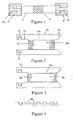
- Figure 1 is a side view of a sampling device fitted with a pair of prior art diffusion-limiting end-caps;
- Figure 2 is a side view of an end-cap;
- Figure 3 is a side view of an end-cap; and
- Figure 4 is a section through a portion of the channelled surface of the insert of Figure 2.
- Referring to Figure 1, a sampling device is shown comprising an
elongate sampling tube 2 containing an adsorbent material 4. - The opposite ends of the tube are fitted with respective prior art end-
caps 6, 8, each cap being formed with arespective passage 10,12 therethrough to allow limited diffusion of gases into or out of thetube 2. - To obtain an atmospheric sample, the end-
caps 6, 8 are removed and the device left at a test location for a predetermined period of time. During this time, gases enter the device, with the adsorbent material 4 retaining any volatile organic compounds (VOCs) present in the gases. The end-caps 6, 8 are subsequently re-fitted to thetube 2 which is then transported to a second location for analysis. - To analyse the sample, one end of the device is connected to an analytical instrument and the other end of the device is connected to a source of inert gas. The
tube 2 is heated to release, from the adsorbing material 4, any VOCs that may have been adsorbed during the test period, with the released VOCs being driven into the analytical instrument by the flow of inert gas through the tube. - The small diameter of the
passages 10,12 formed by the channelling in the end-caps 6,8 limits the uptake of any contaminants whilst the device awaits processing. Thus the ends of the device need not be sealed between the sampling and subsequent analysis operations. - As explained above, to limit the rate of uptake of VOCs by the device to the extent required in many modern sampling applications, it is necessary to provide a very long passage in the each of the end caps. This object may be achieved according to the present invention in one of two ways.
- Firstly, a cap of the type shown in Figure 2 may be fitted to one or both ends of a sampling tube. The cap of Figure 2 comprises a
sleeve 14 having anend portion 16 of increased internal diameter and fitted with an O-ring seal 18 for securing the cap to the open end of a sampling tube. The opposite end of thesleeve 14 has a taperedentrance portion 20 for attachment to an analytical instrument. - An
intermediate portion 22 of thesleeve 14 is fitted with acylindrical insert 24, the surface of the insert being formed with ahelical channel 26 along its length. In use, thehelical channel 26 in the or each cap forms a passageway for communicating gases between the interior and the exterior of the tube to which it is fitted. - Alternatively, a cap of the type shown in Figure 3 may be fitted to one or both ends of a sampling tube. The cap of Figure 3 differs from that of Figure 2 in that a
helical channel 28 is formed along aninterior surface portion 30 of thesleeve 32 rather than along the surface of theinsert 34. It will be appreciated that the rate of uptake of VOCs into a tube to which either cap is fitted is determined by the cross-sectional profile, pitch and number of the or each helical channels formed in the sleeve or in the insert of the cap, and by the length of the insert, the latter being readily varied by trimming the insert to an appropriate length. - A preferred rectangular channel profile is shown in Figure 4, in which successive turns 36 of the channel are spaced apart to minimise leakage between those turns.
- The channel formed in the sleeve or in the insert of a cap is preferably cut respectively using an appropriately formed tap or die.
- Caps may be supplied without channels, allowing the purchaser to form one or more channels in the tubular part or in the insert to his own requirements.
- Caps may instead be supplied together with an assortment of interchangeable inserts each having a different length, cross-sectional channel profile, channel pitch and or number of channels.
- It would also remain in accordance with the present invention for inserts to be fitted directly into the opposite ends of a sample tube.
- The arrangements thus described provide a convenient means for obtaining and processing atmospheric samples.
Claims (4)
- A method of analysing a sample held within a sampling device (2), the method comprising the steps of
providing a cap comprising a sleeve (14) and a cylindrical insert (24), one or other of the opposed surfaces of the sleeve (14) and the insert (24) being formed with at least one helical channel (26, 28) such that, when the insert (24) is fitted into the sleeve (14), the or each helical channel (26,28) forms a respective passage through which gases may pass;
fitting the cap to the sampling device (2) following a sampling period;
and offering the device (2) to an analytical instrument which provides a flow of gas through the sampling device to drive the sample out of the device (2) through the cap. - A method as claimed in Claim 1, wherein the sampling device (2) is fitted with a second cap comprising a sleeve (14) and a cylindrical insert (24), one or other of the opposed surfaces of the sleeve (14) and the insert (24) of the second cap being formed with at least one helical channel (26,28) such that, when the insert (24) is fitted into the sleeve (14), the or each helical channel (26,28) forms a respective passage through which gases may pass, the flow of gas being introduced into the device (2) through the passage or passages formed in the second cap, to drive the sample out of the device (2) through the passage or passages formed in the first cap.
- A method of analysing a sample held within a sampling device (2) having a tubular opening, the method comprising the steps of fitting a cylindrical insert (24) into the opening following a sampling period, and offering the sampling device (2) to an analytical instrument which provides a flow of gas through the sampling device to drive the sample out of the device (2) through at least one passage formed by a respective helical channel (26,28) formed in one or other of the opposed surfaces of the tubular opening and the insert (24).
- A method as claimed in Claim 3, wherein the device (2) comprises a second opening fitted with a cylindrical insert (24), the flow of gas being introduced into the device (2) through at least one passage formed by a respective helical channel (26,28)formed in one or other of the opposed surfaces of the second opening and its respective insert (24) to drive the sample out of the device (22) through said at least one passage formed by a respective helical channel (26,28) formed in one or other of the opposed surfaces of the first tubular opening and its respective insert 24.
Applications Claiming Priority (4)
| Application Number | Priority Date | Filing Date | Title |
|---|---|---|---|
| GBGB9930125.1A GB9930125D0 (en) | 1999-12-22 | 1999-12-22 | Sampling device |
| GB9930125 | 1999-12-22 | ||
| US09/501,821 US6564656B1 (en) | 1998-05-19 | 2000-02-10 | Sampling device |
| US501821 | 2000-02-10 |
Publications (3)
| Publication Number | Publication Date |
|---|---|
| EP1111365A2 EP1111365A2 (en) | 2001-06-27 |
| EP1111365A3 EP1111365A3 (en) | 2004-02-11 |
| EP1111365B1 true EP1111365B1 (en) | 2006-08-16 |
Family
ID=26316134
Family Applications (1)
| Application Number | Title | Priority Date | Filing Date |
|---|---|---|---|
| EP00311381A Expired - Lifetime EP1111365B1 (en) | 1999-12-22 | 2000-12-19 | Sampling method using a cap with a helical gas passage. |
Country Status (5)
| Country | Link |
|---|---|
| US (1) | US6564656B1 (en) |
| EP (1) | EP1111365B1 (en) |
| AT (1) | ATE336711T1 (en) |
| DE (1) | DE60030080T2 (en) |
| GB (1) | GB2359070B (en) |
Families Citing this family (8)
| Publication number | Priority date | Publication date | Assignee | Title |
|---|---|---|---|---|
| GB2433122B (en) * | 2005-12-10 | 2008-07-23 | Endet Ltd | Gas sampling probe |
| ES2873089T3 (en) * | 2010-02-01 | 2021-11-03 | Vero Biotech LLC | Nitric Oxide Delivery System |
| WO2014043127A2 (en) * | 2012-09-13 | 2014-03-20 | Geosyntec Consultants, Inc. | Passive sampling device and method of sampling and analysis |
| FR3003789B1 (en) * | 2013-03-28 | 2015-05-01 | Commissariat Energie Atomique | METHOD FOR MANUFACTURING AN OBJECT COMPRISING AT LEAST ONE FILET, SUCH OBJECT BEING IN A CURED INORGANIC OR ORGANIC MATERIAL |
| CN106796217A (en) * | 2014-07-21 | 2017-05-31 | 泰克年研究发展基金会公司 | For the composition of directly breathing sampling |
| EP3203203B1 (en) * | 2014-10-03 | 2018-12-19 | TLV Co., Ltd. | Sensor device |
| CN106838314B (en) * | 2017-04-18 | 2018-11-20 | 龙昌耀 | Exhausting seal ring |
| CN114917968A (en) * | 2022-05-06 | 2022-08-19 | 北京国仪精测技术有限公司 | Sample tube, sample tube assembly and sample analysis instrument of sample analysis instrument |
Family Cites Families (12)
| Publication number | Priority date | Publication date | Assignee | Title |
|---|---|---|---|---|
| GB875065A (en) | 1957-09-26 | 1961-08-16 | Permuta Closures Ltd | Improvements in or relating to stoppers |
| US3915008A (en) * | 1974-07-26 | 1975-10-28 | Vilter Manufacturing Corp | Gauge mounting |
| US4046014A (en) * | 1975-06-20 | 1977-09-06 | Boehringer John R | Sealable activated charcoal gas sampler |
| DK148782C (en) | 1980-10-31 | 1986-04-21 | Radiometer As | PROCEDURE AND CLOSURE CAP FOR ANAEROBIC SEALING OF A BLOOD TEST CAPILLAR |
| US4389372A (en) * | 1981-07-13 | 1983-06-21 | Lalin Hill S | Portable holder assembly for gas detection tube |
| US4790857A (en) * | 1986-11-20 | 1988-12-13 | Miksch Robert R | Gaseous contaminant dosimeter with diffusive material for regulating mass uptake |
| BE1003879A3 (en) | 1990-04-20 | 1992-07-07 | Saint Denis S A Nv Atel | Degassing device for containers containers equipped with a device. |
| US5228334A (en) * | 1990-12-28 | 1993-07-20 | Hi-Stat Manufacturing Co., Inc. | Pressure transducer |
| US5231874A (en) * | 1991-08-21 | 1993-08-03 | Halliburton Logging Services Inc. | Buffer arrangement with back flushing of a quartz pressure transducer in a formation testing device |
| US5482677A (en) * | 1993-05-14 | 1996-01-09 | Shell Oil Company | Thermally desorbable passive dosimeter |
| US5574230A (en) * | 1994-10-20 | 1996-11-12 | Havelick & Associates, Ltd. | Silica gel, Tenax, and carbon media adsorption tube for the sampling of a wide variety of organic compounds in air and gas streams |
| GB2337513B (en) * | 1998-05-19 | 2002-09-25 | Markes Int Ltd | Sample tube caps |
-
2000
- 2000-02-10 US US09/501,821 patent/US6564656B1/en not_active Expired - Lifetime
- 2000-12-19 EP EP00311381A patent/EP1111365B1/en not_active Expired - Lifetime
- 2000-12-19 AT AT00311381T patent/ATE336711T1/en not_active IP Right Cessation
- 2000-12-19 DE DE60030080T patent/DE60030080T2/en not_active Expired - Lifetime
- 2000-12-19 GB GB0030984A patent/GB2359070B/en not_active Expired - Lifetime
Also Published As
| Publication number | Publication date |
|---|---|
| DE60030080D1 (en) | 2006-09-28 |
| ATE336711T1 (en) | 2006-09-15 |
| GB2359070B (en) | 2002-12-04 |
| US6564656B1 (en) | 2003-05-20 |
| DE60030080T2 (en) | 2006-12-14 |
| GB0030984D0 (en) | 2001-01-31 |
| EP1111365A2 (en) | 2001-06-27 |
| EP1111365A3 (en) | 2004-02-11 |
| GB2359070A (en) | 2001-08-15 |
Similar Documents
| Publication | Publication Date | Title |
|---|---|---|
| AT393565B (en) | DISPOSABLE MEASURING ELEMENT | |
| EP1451553B1 (en) | Device and method for micro sorbent extraction and desorption | |
| EP1111365A2 (en) | Sampling device | |
| US4876068A (en) | Test kit for colorimetric analysis | |
| EP1146335B1 (en) | Method for analysing gaseous contents and test kit for carrying out the method | |
| US20050011831A1 (en) | Method and device for solid phase microextraction and desorption | |
| US20050096563A1 (en) | Oral fluid sampling device and method | |
| DE102014203815B4 (en) | Wine analysis method and associated apparatus | |
| WO1998041855A1 (en) | Method and device for solid phase microextraction and desorption | |
| US20030003596A1 (en) | Method and device for solid phase microextraction and desorption | |
| CA2009869A1 (en) | Apparatus and method for periodic aseptic withdrawal of liquid samples from a sterile liquid source | |
| EP0753153A1 (en) | Analysis method and analysis apparatus | |
| EP1039288A2 (en) | Method for solid phase micro-extraction, analysis and collector therefor | |
| EP1607134B1 (en) | Polyorganosiloxane-based sorbent trap | |
| US5221311A (en) | Evacuated sampling vial | |
| FI65386C (en) | SAEKERHETSANORDNING FOER TILLSLUTNING AV PROVROER | |
| EP0297441A2 (en) | Inverted separation and transfer device, and process for using same | |
| US4481297A (en) | Vapor detection tube and method of testing for a vapor | |
| DE69920403T2 (en) | DEVICE FOR QUALIFYING PRODUCTS WITH LIGHT-FLUID INGREDIENTS | |
| US4920057A (en) | Method for colorimetric analysis of metals | |
| US20070163436A1 (en) | Adsorbent Transfer for Passive Sampling Badge | |
| US20020148355A1 (en) | Passive sampling badge | |
| US4445390A (en) | Sampling tube and apparatus | |
| US5578770A (en) | Apparatus and method for gas detection | |
| DE4206109C2 (en) | Method and device for processing solid samples with the aid of pyrolytic evaporation for analysis by means of a mass spectrometer or a gas chromatograph |
Legal Events
| Date | Code | Title | Description |
|---|---|---|---|
| PUAI | Public reference made under article 153(3) epc to a published international application that has entered the european phase |
Free format text: ORIGINAL CODE: 0009012 |
|
| AK | Designated contracting states |
Kind code of ref document: A2 Designated state(s): AT BE CH CY DE DK ES FI FR GB GR IE IT LI LU MC NL PT SE TR |
|
| AX | Request for extension of the european patent |
Free format text: AL;LT;LV;MK;RO;SI |
|
| PUAL | Search report despatched |
Free format text: ORIGINAL CODE: 0009013 |
|
| AK | Designated contracting states |
Kind code of ref document: A3 Designated state(s): AT BE CH CY DE DK ES FI FR GB GR IE IT LI LU MC NL PT SE TR |
|
| AX | Request for extension of the european patent |
Extension state: AL LT LV MK RO SI |
|
| 17P | Request for examination filed |
Effective date: 20040803 |
|
| AKX | Designation fees paid |
Designated state(s): AT BE CH CY DE DK ES FI FR GB GR IE IT LI LU MC NL PT SE TR |
|
| GRAP | Despatch of communication of intention to grant a patent |
Free format text: ORIGINAL CODE: EPIDOSNIGR1 |
|
| RTI1 | Title (correction) |
Free format text: SAMPLING METHOD USING A CAP WITH A HELICAL GAS PASSAGE. |
|
| GRAS | Grant fee paid |
Free format text: ORIGINAL CODE: EPIDOSNIGR3 |
|
| GRAA | (expected) grant |
Free format text: ORIGINAL CODE: 0009210 |
|
| AK | Designated contracting states |
Kind code of ref document: B1 Designated state(s): AT BE CH CY DE DK ES FI FR GR IE IT LI LU MC NL PT SE TR |
|
| PG25 | Lapsed in a contracting state [announced via postgrant information from national office to epo] |
Ref country code: IT Free format text: LAPSE BECAUSE OF FAILURE TO SUBMIT A TRANSLATION OF THE DESCRIPTION OR TO PAY THE FEE WITHIN THE PRESCRIBED TIME-LIMIT;WARNING: LAPSES OF ITALIAN PATENTS WITH EFFECTIVE DATE BEFORE 2007 MAY HAVE OCCURRED AT ANY TIME BEFORE 2007. THE CORRECT EFFECTIVE DATE MAY BE DIFFERENT FROM THE ONE RECORDED. Effective date: 20060816 Ref country code: LI Free format text: LAPSE BECAUSE OF FAILURE TO SUBMIT A TRANSLATION OF THE DESCRIPTION OR TO PAY THE FEE WITHIN THE PRESCRIBED TIME-LIMIT Effective date: 20060816 Ref country code: BE Free format text: LAPSE BECAUSE OF FAILURE TO SUBMIT A TRANSLATION OF THE DESCRIPTION OR TO PAY THE FEE WITHIN THE PRESCRIBED TIME-LIMIT Effective date: 20060816 Ref country code: FI Free format text: LAPSE BECAUSE OF FAILURE TO SUBMIT A TRANSLATION OF THE DESCRIPTION OR TO PAY THE FEE WITHIN THE PRESCRIBED TIME-LIMIT Effective date: 20060816 Ref country code: AT Free format text: LAPSE BECAUSE OF FAILURE TO SUBMIT A TRANSLATION OF THE DESCRIPTION OR TO PAY THE FEE WITHIN THE PRESCRIBED TIME-LIMIT Effective date: 20060816 Ref country code: NL Free format text: LAPSE BECAUSE OF FAILURE TO SUBMIT A TRANSLATION OF THE DESCRIPTION OR TO PAY THE FEE WITHIN THE PRESCRIBED TIME-LIMIT Effective date: 20060816 Ref country code: CH Free format text: LAPSE BECAUSE OF FAILURE TO SUBMIT A TRANSLATION OF THE DESCRIPTION OR TO PAY THE FEE WITHIN THE PRESCRIBED TIME-LIMIT Effective date: 20060816 |
|
| REG | Reference to a national code |
Ref country code: CH Ref legal event code: EP |
|
| REG | Reference to a national code |
Ref country code: IE Ref legal event code: FG4D |
|
| REF | Corresponds to: |
Ref document number: 60030080 Country of ref document: DE Date of ref document: 20060928 Kind code of ref document: P |
|
| PG25 | Lapsed in a contracting state [announced via postgrant information from national office to epo] |
Ref country code: SE Free format text: LAPSE BECAUSE OF FAILURE TO SUBMIT A TRANSLATION OF THE DESCRIPTION OR TO PAY THE FEE WITHIN THE PRESCRIBED TIME-LIMIT Effective date: 20061116 Ref country code: DK Free format text: LAPSE BECAUSE OF FAILURE TO SUBMIT A TRANSLATION OF THE DESCRIPTION OR TO PAY THE FEE WITHIN THE PRESCRIBED TIME-LIMIT Effective date: 20061116 |
|
| PG25 | Lapsed in a contracting state [announced via postgrant information from national office to epo] |
Ref country code: ES Free format text: LAPSE BECAUSE OF FAILURE TO SUBMIT A TRANSLATION OF THE DESCRIPTION OR TO PAY THE FEE WITHIN THE PRESCRIBED TIME-LIMIT Effective date: 20061127 |
|
| PG25 | Lapsed in a contracting state [announced via postgrant information from national office to epo] |
Ref country code: IE Free format text: LAPSE BECAUSE OF NON-PAYMENT OF DUE FEES Effective date: 20061219 |
|
| PG25 | Lapsed in a contracting state [announced via postgrant information from national office to epo] |
Ref country code: MC Free format text: LAPSE BECAUSE OF NON-PAYMENT OF DUE FEES Effective date: 20061231 |
|
| PG25 | Lapsed in a contracting state [announced via postgrant information from national office to epo] |
Ref country code: PT Free format text: LAPSE BECAUSE OF FAILURE TO SUBMIT A TRANSLATION OF THE DESCRIPTION OR TO PAY THE FEE WITHIN THE PRESCRIBED TIME-LIMIT Effective date: 20070116 |
|
| NLV1 | Nl: lapsed or annulled due to failure to fulfill the requirements of art. 29p and 29m of the patents act | ||
| REG | Reference to a national code |
Ref country code: CH Ref legal event code: PL |
|
| ET | Fr: translation filed | ||
| PLBE | No opposition filed within time limit |
Free format text: ORIGINAL CODE: 0009261 |
|
| STAA | Information on the status of an ep patent application or granted ep patent |
Free format text: STATUS: NO OPPOSITION FILED WITHIN TIME LIMIT |
|
| 26N | No opposition filed |
Effective date: 20070518 |
|
| PG25 | Lapsed in a contracting state [announced via postgrant information from national office to epo] |
Ref country code: GR Free format text: LAPSE BECAUSE OF FAILURE TO SUBMIT A TRANSLATION OF THE DESCRIPTION OR TO PAY THE FEE WITHIN THE PRESCRIBED TIME-LIMIT Effective date: 20061117 |
|
| PG25 | Lapsed in a contracting state [announced via postgrant information from national office to epo] |
Ref country code: TR Free format text: LAPSE BECAUSE OF FAILURE TO SUBMIT A TRANSLATION OF THE DESCRIPTION OR TO PAY THE FEE WITHIN THE PRESCRIBED TIME-LIMIT Effective date: 20060816 Ref country code: LU Free format text: LAPSE BECAUSE OF NON-PAYMENT OF DUE FEES Effective date: 20061219 |
|
| PG25 | Lapsed in a contracting state [announced via postgrant information from national office to epo] |
Ref country code: CY Free format text: LAPSE BECAUSE OF FAILURE TO SUBMIT A TRANSLATION OF THE DESCRIPTION OR TO PAY THE FEE WITHIN THE PRESCRIBED TIME-LIMIT Effective date: 20060816 |
|
| REG | Reference to a national code |
Ref country code: FR Ref legal event code: PLFP Year of fee payment: 16 |
|
| REG | Reference to a national code |
Ref country code: FR Ref legal event code: PLFP Year of fee payment: 17 |
|
| REG | Reference to a national code |
Ref country code: FR Ref legal event code: PLFP Year of fee payment: 18 |
|
| PGFP | Annual fee paid to national office [announced via postgrant information from national office to epo] |
Ref country code: DE Payment date: 20191210 Year of fee payment: 20 |
|
| PGFP | Annual fee paid to national office [announced via postgrant information from national office to epo] |
Ref country code: FR Payment date: 20191219 Year of fee payment: 20 |
|
| REG | Reference to a national code |
Ref country code: DE Ref legal event code: R071 Ref document number: 60030080 Country of ref document: DE |