EP1111361A2 - Combustion pressure sensor - Google Patents
Combustion pressure sensor Download PDFInfo
- Publication number
- EP1111361A2 EP1111361A2 EP00127800A EP00127800A EP1111361A2 EP 1111361 A2 EP1111361 A2 EP 1111361A2 EP 00127800 A EP00127800 A EP 00127800A EP 00127800 A EP00127800 A EP 00127800A EP 1111361 A2 EP1111361 A2 EP 1111361A2
- Authority
- EP
- European Patent Office
- Prior art keywords
- combustion pressure
- pressure sensor
- screw
- hole
- plug body
- Prior art date
- Legal status (The legal status is an assumption and is not a legal conclusion. Google has not performed a legal analysis and makes no representation as to the accuracy of the status listed.)
- Ceased
Links
Images





Classifications
-
- G—PHYSICS
- G01—MEASURING; TESTING
- G01L—MEASURING FORCE, STRESS, TORQUE, WORK, MECHANICAL POWER, MECHANICAL EFFICIENCY, OR FLUID PRESSURE
- G01L23/00—Devices or apparatus for measuring or indicating or recording rapid changes, such as oscillations, in the pressure of steam, gas, or liquid; Indicators for determining work or energy of steam, internal-combustion, or other fluid-pressure engines from the condition of the working fluid
- G01L23/22—Devices or apparatus for measuring or indicating or recording rapid changes, such as oscillations, in the pressure of steam, gas, or liquid; Indicators for determining work or energy of steam, internal-combustion, or other fluid-pressure engines from the condition of the working fluid for detecting or indicating knocks in internal-combustion engines; Units comprising pressure-sensitive members combined with ignitors for firing internal-combustion engines
- G01L23/221—Devices or apparatus for measuring or indicating or recording rapid changes, such as oscillations, in the pressure of steam, gas, or liquid; Indicators for determining work or energy of steam, internal-combustion, or other fluid-pressure engines from the condition of the working fluid for detecting or indicating knocks in internal-combustion engines; Units comprising pressure-sensitive members combined with ignitors for firing internal-combustion engines for detecting or indicating knocks in internal combustion engines
- G01L23/222—Devices or apparatus for measuring or indicating or recording rapid changes, such as oscillations, in the pressure of steam, gas, or liquid; Indicators for determining work or energy of steam, internal-combustion, or other fluid-pressure engines from the condition of the working fluid for detecting or indicating knocks in internal-combustion engines; Units comprising pressure-sensitive members combined with ignitors for firing internal-combustion engines for detecting or indicating knocks in internal combustion engines using piezoelectric devices
-
- G—PHYSICS
- G01—MEASURING; TESTING
- G01L—MEASURING FORCE, STRESS, TORQUE, WORK, MECHANICAL POWER, MECHANICAL EFFICIENCY, OR FLUID PRESSURE
- G01L23/00—Devices or apparatus for measuring or indicating or recording rapid changes, such as oscillations, in the pressure of steam, gas, or liquid; Indicators for determining work or energy of steam, internal-combustion, or other fluid-pressure engines from the condition of the working fluid
- G01L23/08—Devices or apparatus for measuring or indicating or recording rapid changes, such as oscillations, in the pressure of steam, gas, or liquid; Indicators for determining work or energy of steam, internal-combustion, or other fluid-pressure engines from the condition of the working fluid operated electrically
- G01L23/10—Devices or apparatus for measuring or indicating or recording rapid changes, such as oscillations, in the pressure of steam, gas, or liquid; Indicators for determining work or energy of steam, internal-combustion, or other fluid-pressure engines from the condition of the working fluid operated electrically by pressure-sensitive members of the piezoelectric type
-
- F—MECHANICAL ENGINEERING; LIGHTING; HEATING; WEAPONS; BLASTING
- F23—COMBUSTION APPARATUS; COMBUSTION PROCESSES
- F23Q—IGNITION; EXTINGUISHING-DEVICES
- F23Q7/00—Incandescent ignition; Igniters using electrically-produced heat, e.g. lighters for cigarettes; Electrically-heated glowing plugs
- F23Q7/001—Glowing plugs for internal-combustion engines
- F23Q2007/002—Glowing plugs for internal-combustion engines with sensing means
Definitions
- a glow plug with combustion pressure sensor J1 is provided with a plug body (unique to the glow plug) 200 that holds a heater 206 (heated when a current is supplied in the housing 201) a combustion pressure sensor (pressure sensor) 30 fixed to the plug body 200 for detecting a combustion pressure in an engine based on combustion pressure force exerted on the plug body 200, and a lead wire 500 outputting a signal from the combustion pressure sensor 30.
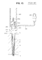
- the plug body 200 is inserted into the screw hole 1b of the engine head 1 in this state, the hexagonal portion 201b is turned round the axis by use of a plug wrench 900 (refer to FIG. 15), only the plug body 200 is fastened to the screw hole 1b for holding and fixing. Then, the hexagonal portion 312 of a nut of the combustion pressure sensor 30 is turned round the axis along the fixing screw 201a of the housing 201 for fastening to hold and fix the bottom surface of the combustion pressure sensor 30 against the pedestal surface (surface) le of the engine head 1.
- the invention described in a first aspect provides a combustion pressure sensor characterized in that the outer diameter of the end including the nut portion (221, 701b, 801b) of the structure (220, 700, 800) inserted into the screw hole (1b) is smaller than the inside diameter of the through hole (31a to 37a) of the combustion pressure sensor (31 to 37). Therefore, the structure can be inserted into the through hole of the combustion pressure sensor from the other end of the structure.
- the screw portion (311) is formed on the inside surface of the through hole (31a, 33a, 34a) of the combustion pressure sensor (31, 33, 34) into which the structure (200, 220, 700, 800) is inserted, and the screw portion (201a, 701a, 801a) of the structure is screw-connected to the screw portion of the though hole to thereby fix the combustion pressure sensor to the structure (the inventions described in the second aspect and a fifth aspect).
- the combustion pressure sensor (32, 35 to 37) can be fixed to the structure by the axial force of the separate nut (600), which is a separate member from the combustion pressure sensor, that is screw-connected to the screw portion (201a, 701a, 801a) of the structure (200, 220, 700, 800). In this case, it is not necessary to form the screw portion on the combustion pressure sensor.
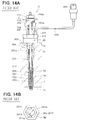
- FIG. 14A is a cross sectional view illustrating the general structure of a conventional glow plug with combustion pressure sensor according to the prior art
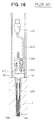
- FIG. 16 is a cross sectional view of the attachment of a combustion pressure sensor of a glow plug according to the prior art.
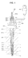
- the engine head 1 consists of, for example, aluminum alloy or iron, and a screw hole (plug hole, fixing hole) 1b that penetrates from the outer surface to the inside combustion chamber 1a is formed on the engine head 1.
- the one end (lower side in FIG. 1) of the plug body (structure) 220 is inserted into the screw hole 1b and screw-fixed firmly.
- a housing 201 of the plug body 220 is a hollow pipe consisting of metal (low carbon steel or the like).
- a fixing screw (referred to as a screw portion of the structure in the present invention) 201a served for screw-connection to the screw hole 1b is formed, and on the other end (upper side in FIG. 1) the hexagonal portion (referred to as nut portion of the structure in the present invention) 221 for providing rotational force round the axis for the screw connection is formed.
- the plug body 220 is turned round the axis by means of the hexagonal portion 221 to thereby be screw-connected to the screw portion 1c of the screw hole 1b, and thus the plug body 220 is fixed to the screw hole 1b.
- the combustion pressure sensor 31 is a ring component having the screw portion 311 (refer to FIG. 3 that will be described hereinafter) formed on the inside surface of the through hole 31a.
- the plug body (structure) 220 is inserted into the through hole 31a of the sensor 31, and the combustion pressure sensor 31 is fixed to the fixing screw 201a of the plug body 220 by means of screw connection.
- the combustion pressure sensor 31 is fixed to the outer peripheral surface of the projection at the portion of the plug body 220 that projects from the surface of the engine head 1 to the axis direction as shown in FIG. 1, and the combustion pressure sensor 31 is located in contact with the bearing surface (surface) le of the engine head 1.
- the outside diameter of the other end including the hexagonal portion (nut portion) 221 out of the plug body (structure) 220 is smaller than the inside diameter of the through hole 31a of the combustion pressure sensor 31 (screw inside diameter 311a shown in FIG.2B).
- the plug body 220 can be inserted into the through hole 31a of the combustion pressure sensor 31 from the other end. The detail of this structure will be described with comparison with the conventional art J1 shown in FIG. 14.
- the screw portion 311 on the inside surface of the through hole 30a of the combustion pressure sensor 30 is a female screw of M10 and 1.25 mm pitch so as to fit to the male screw.
- the minimum diameter of the screw portion 311 on which the female screw is formed of the sensor 30, namely the inside diameter of the screw is, for example, 8.7 mm.
- the standardized hexagonal portion 201b having the outside diameter larger than the screw inside diameter 311a of the combustion pressure sensor 30 is formed on the end of the housing 201 (refer to FIG. 14B).
- the width across flats of the hexagonal 201c is 12 mm, and the distance between facing apex angles 201d (distance between apex angles) is 13.8 mm. Therefore, in the conventional art, the sensor 30 is not inserted from the hexagonal portion 201b side.
- the combustion pressure sensor 30 is not inserted from the hexagonal portion 201b end surface side of the plug body 200 in the cast of the conventional art J1.
- the combustion pressure sensor 31 can be inserted from the hexagonal portion 221 end surface side (other end) of the plug body 200 in the present embodiment.
- the distance between apex angles 221b, that is the maximum outside size portion of the hexagonal portion 221 of the plug body 220, is smaller than the screw inside diameter 311a of the combustion pressure sensor 31.
- the outside size of all the portions located from the hexagonal portion 221 to the fixing screw 201a of the housing 201 is smaller than the screw inside diameter 311a of the sensor 31.
- the center shaft 204 is fixed to the housing 201 with the fixing nut 210 along the terminal screw 204a provided on the center shaft 204 with interposition of an insulating bush 209 consisting of insulating resin such as phenol or the like.
- the insulating bush 209 is also for preventing contact short-circuit between the center shaft 204 and the housing 201.
- the center shaft 224, insulating bush 229, and fixing nut 230 having a small diameter are used in the inside of the housing 201 having a small diameter.
- the air-tight rubber 228 consisting of molded rubber having a taper shape is used to ensure the centering of the center shaft 224 and to ensure the water-proofing and air-tightness in the housing 201.
- the O-ring 208 and the washer 207 that are used conventionally are eliminated.
- the hexagonal portion 221 and relating portions that are unique for the present embodiment are described hereinabove, and other portions of the glow plug with combustion pressure sensor 100 will be described further with reference to FIG. 1.
- the one end of the heating coil 203 is connected to the one end of the sheathed tube 202, and the other end of the heating coil 203 is connected to the one end of the center shaft 224.
- Insulating powder 205 consisting of heat-resistant magnesium oxide is filled between the heating coil 203 and the center shaft 224 and the sheathed tube 202.
- the sheathed tube 202 is drawn by swaging. Thereby, the insulating powder 205 filled in the inside is compacted, and the sheathed tube 202, the center shaft 224, and the heating coil 203 are held and fixed firmly with the insulating powder 205.
- the heater 206 comprises the sheathed tube 202, the heating coil 203, and the insulating powder 205.
- the heater 206 is connected and held in the inside of the housing 201 so that the one end (one end of the sheathed tube 202) is exposed.
- the heater 206 (the outer peripheral surface of the sheathed tube 202) and the housing 201 may be connected together by means of pressure engagement fitting or brazing with silver solder.
- a connecting bar not shown in the drawing is fixed to the terminal screw 204a provided on the other end of the center shaft 224 with a terminal nut as in the same manner as shown in FIG. 14 for electrical connection.
- the connecting bar is connected to a power source not shown in the drawing, and earthed to the engine head 1 through the center shaft 224, heating coil 203, sheathed tube 202, and housing 201. Thereby, the heater 206 is heated in the glow plug 100 so as to function for ignition start auxiliary action of the diesel engine.
- the nut 310 and the lead portion 330 will be described.
- the nut 310 consisting of metal is provided with the above-mentioned screw portion 311 and hexagonal portion 312 for attaching and fixing the sensor body with the fixing screw 201a of the housing 201 and is fixed to the outer periphery of the housing 201. Furthermore, under the hexagonal portion 312, a large diameter portion and small diameter portion 314 are formed in this order, and a heat-shrinkable insulating tube 315 consisting of silicon is fixed tightly on the outer peripheral surface of a small diameter portion.
- the lead portion 330 electrically connects between the piezoelectric element portion 320 and the one end of the lead wire 500, and is provided with an electrode 331, an insulator 332, a fixing metal member 333, and one end of the lead wire 500 as structural component.
- the electrode 331 is a ring metal member
- the electrode 331 and insulator 332 are fitted on the outer edge of a small diameter portion 314 of the nut 310 covered with the insulating tube 315.
- the signal leading wire 501 is welded and connected to the electrode 331 in the hole 331a formed on the electrode 331 through the hole 316 formed on the nut 310 and cutout portion 332a formed on the insulator 332.
- the other end of the lead wire 500 is connected to the connector 400 to be connected electrically to the external circuit (ECU or the like of an vehicle).
- the pedestal 340 is a metal ring, on which a lock washer 341 is formed at the end surface side that contacts engine head 1.
- the lock washer 341 corresponds to the oval-shaped detent 317 formed on the end of a small diameter portion 314 of the nut 310, and the lock washer 341 is oval-shaped so as to be fitted to the detent 317 easily. Thereby, the deviation round the axis of the plug between the nut 310 and the pedestal 340 is prevented.
- the pedestal 340 is pressed on the surface of the engine head 1 by means of axial force (screwing force) of the nut 310. Furthermore, the piezoelectric element portion 320, the electrode 331, and the insulator 332 are fixedly held and interposed between the nut 310 and the pedestal 340 by means of the axial force of the nut 310.
- the piezoelectric element portion 320 comprising the piezoelectric ceramics 321 and both washer rings 322 and 323 is inserted into a small diameter portion 314 of the nut 310.
- the pedestal 340 that has been combined with the metal case 350 by brazing or the like is inserted into a small diameter portion 314 of the nut 310.
- the detent 317 is coincides with the lock washer 341.
- the metal case 350 and large diameter portion 313 are joined by laser welding, maintaining the pedestal 340 and the nut 310 in close contact.
- the combustion pressure sensor 31 is completed.
- the combustion pressure sensor 31 is attached to the plug body 220.
- the plug body 220 because the outside diameter of the other end including the hexagonal portion 221 out of the plug body 220 is smaller than the screw inside diameter 311a of the combustion pressure sensor 31 as described hereinabove, the plug body 220 can be inserted into the through hole 31a of the combustion pressure sensor 31 from the other end.
- the length L2 ranging from the housing bottom end surface 201e to the bottom end surface of the combustion pressure sensor 30 is equal to or shorter than the depth L1 (plug hole depth, refer to FIG. 4B) of the screw hole 1b ranging from the taper bearing surface portion 1d to the bearing surface le of the engine head 1, for example, as shown in FIG. 4A, in the state that the combustion pressure sensor 30 is temporarily attached to the fixing screw 201a of the plug body 200. If the plug body 200 is tightened further in this state, then the bottom end surface of the combustion pressure sensor 30 is brought into contact with the bearing surface le of the engine head 1 before the housing taper portion 212 is brought into contact with the taper bearing surface portion 1d, and the space S remains as shown in FIG. 4B.
- the combustion gas namely combustion pressure
- the performance of the combustion pressure sensor 30 is deteriorated due to thermal effect
- the engine output is decreased
- These malfunctions give make a driver feel unpleasant.
- the combustion pressure sensor 31 can be attached to the plug body 220 after the plug body (structure) 220 is screw-connected to the screw hole 1b of the engine, such erroneous attachment problem as described hereinabove is prevented.
- FIG. 5 is a schematic cross sectional view.
- the female screw is not formed on the through hole 32a of the ring-shaped combustion pressure sensor 32 as shown in FIG. 5.
- a separate nut 600 having screw alone function is combined, and the same effect as obtained in the above-mentioned example is obtained. Because the structure of the combustion pressure sensor 32 (pressure sensor) used in the present modified example is somewhat different from that of the above-mentioned combustion pressure sensor 31, the detailed structure of the combustion pressure sensor 32 will be described with reference to FIG. 5.
- the combustion pressure sensor 32 is fabricated as described herein under.
- a heat-shrinkable insulation tube 306 consisting of silicon is heated and fit on the circumferential side surface of a small diameter portion 303c of the metal case 303.
- the piezoelectric ceramic 302, the electrode 301, and the piezoelectric ceramic 302 are put on a small diameter portion 303c of the metal case in that order.
- the insulation tube 306 prevents electrical short-circuit between the piezoelectric ceramics 302, the electrode 301, and the metal case 303.
- the combustion pressure sensor 32 is fit to the plug body 220 that has been attached to the screw hole 1b from the other end (hexagonal portion 221 side) and a separate nut 600 is also fit.
- the separate nut 600 is tightened along the fixing screw 201a of the housing 201 to thereby fixedly support the combustion pressure sensor on the surface of the engine head 1.
- attachment of the glow plug with combustion pressure sensor 100 having the combustion pressure sensor 32 of the present modified example is completed.
- the combustion pressure sensor 32 is fixed to the plug body 220 by means of the axial force of the separate nut 600 that has been screw-connected to the fixing screw 201a of the plug body 220.
- the shielded wire (lead wire) 305 is drawn in a direction different from the action direction of the axial force of the separate nut 600 with respect to the combustion pressure sensor 32, namely in the direction of circumferential side surface of the combustion pressure sensor 32. Thereby, the interference between the separate nut 600 and the lead wire 305 is prevented efficiently.
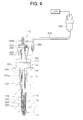
- the second embodiment is a glow plug with combustion pressure sensor served as a combustion pressure sensor having a lead wire that is detachable from the combustion pressure sensor.
- FIG. 6 is a partial vertical cross sectional view illustrating the whole structure of a glow plug with combustion pressure sensor 110 in accordance with the present embodiment that is attached to an engine head 1 of a diesel engine.
- the conventional plug body 200 shown in FIG. 14 is used and the combustion pressure sensor 33 is changed.
- a metal signal leading pin 364 insulation-covered with a two-step cylindrical insulation pipe consisting of fluororesin or the like is inserted into holes 361 and 362 formed on a hexagonal portion 312 of a nut 310.
- the one end portion of the pin 364 is exposed from the insulation pipe 363, and it is needle-shaped to be inserted into a cylindrical pressure attachment terminal 381 of the metal connector 380.
- a connector attachment screw 365 (female screw) that is screw-fixable to a male screw 382 formed on the metal connector 380 is formed around the one end portion of the exposed pin 364.
- the rear end portion of the signal leading pin 364 is inserted into the hole 331a formed on the electrode 331 through a cut 332a formed on the insulator 332, and welded to the electrode 331 for connection.
- the signal leading pin 364 is interposed between the nut 310 and a pedestal 340 with interposition of the insulation pipe 363, insulator 332, piezoelectric ceramics 321, signal leading side washer ring 322, and earth side washer ring 323.
- the insulation pipe 363, signal leading pin 364, and connector attachment screw 365 constitute the sensor body side lead portion 360.
- the metal connector 380 basically comprises a lead wire 500 having a signal leading wire 501, an insulation cover 502, an earth side shield wire 503, and an insulation cover 504, a fixing metal member 384 having the above-mentioned male screw 382 and hexagonal portion 383, and the above-mentioned cylindrical pressure attachment terminal 381 disposed in the fixing metal member 384.
- the cylindrical pressure attachment terminal 381 is insulated from the fixing metal member 384 by means of the insulation pipe 385 consisting of fluororesin or the like and pressure-attached to the signal leading wire 501 for connection.
- the lead wire 500 is fixedly held on the cylindrical portion of the fixing metal member 384 by caulking the insulation cover 504 that is a portion of the lead wire 500 and the earth side shield wire 503 simultaneously on the cylindrical portion of the fixing metal member 384.
- the earth side shield wire 503 is connected electrically to the fixing metal member 384 as the result of caulking pressure attachment, and the insulation ring 386, cylindrical pressure attachment terminal 381, and the insulation pipe 385 contained in the inside are fixed to the fixing metal member 384, and thus the metal connector comprising the lead wire 500 and the fixing metal member 384 is formed.
- the lead wire 500 is detachable from the combustion pressure sensor 33, the lead wire 500 can be attached to the combustion pressure sensor 33 after the plug body (structure) 200 is screw-connected to the screw hole 1b of the engine as described hereinabove. Therefore, the workability is improved without adverse effect of the lead wire connected to the combustion pressure sensor when the combustion pressure sensor is formed.
- the lead wire 500 and connector 400 are not attached when the combustion pressure sensor 33 itself is attached, entanglement of the lead wire 500 and connector 400 (refer to FIG. 16) contained in the conventional socket wrench 910 with the plug body 200 is prevented, and breaking of the lead wire 500 is prevented.
- an air impact wrench can be used for attaching the sensor 33 as in the case of the plug body 200, and the workability and efficiency for attachment are improved.
- a combustion pressure sensor 35 shown in FIG. 9 is the combustion pressure sensor 32 shown in FIG. 5 to which the present embodiment is applied. Also, in the present embodiment, a female screw portion is not formed on the sensor 35, and a separate nut 600 having the screw function is combined. Thereby, the combustion pressure sensor 35 is fixed to the plug body 200 by the axial force of the separate nut 600 that is screw-connected to the fixing screw 201a. As the result, it is not necessary to form a screw portion on the through hole 35a of the combustion pressure sensor 35.
- the third embodiment provides a glow plug with combustion pressure sensor that is served as the combustion pressure sensor, in which a cutout portion that is formed from the periphery to the inside is formed on a combustion pressure sensor and the combustion pressure sensor is disposed so that the cutout portion is engaged with the structure.
- the conventional plug body 200 shown in FIG. 14 is used and the combustion pressure sensors 36 and 37 are changed.
- the glow plug with combustion pressure sensor of the present embodiment is preferably used when it is difficult to miniaturize the hexagonal portion 201b of the plug body 200 as when the above-mentioned second embodiment.
- FIG. 10A is a top view (plan view) of the combustion pressure sensor 36 in accordance with the present embodiment, and 10B is a cross sectional view along the line 10B-10B of 10A.
- This combustion pressure sensor 36 is shaped different from the approximately ring-shaped combustion pressure sensor 32 shown in FIG. 5.
- the same components shown in FIG. 10 are given the same characters shown in FIG. 5, and the detailed description is omitted.
- the combustion pressure sensor 36 of the present embodiment has a cutout portion 36a that is formed by cutting in the form of U-shape from the circumferential side surface to the inside. Therefore, this sensor 36, the electrode 301, piezoelectric ceramics 302, metal case 303, and pedestal 304, which are all ring-shaped in FIG. 5, are cut correspondingly to the cut shape.
- the curve portion of U-shape of the cutout portion 36a is shaped so that the inside peripheral surface of the cutout portion 36a is in contact with the outer peripheral surface of the fixing screw 201a of the plug body 200.
- the combustion pressure sensor 36 can be attached after the plug body 200 is screw-connected to the engine head 1. Therefore, the workability is improved without adverse effect of the shielded wire (lead wire) 305 connected to the combustion pressure sensor 36 when the combustion pressure sensor is formed. Furthermore, because the wire 305 is drawn from the circumferential side surface direction of the sensor 36, interference between the separate nut 600 and the wire 305 is prevented effectively.
- the combustion pressure sensor 37 shown in FIG. 11 as the modified example of the present embodiment is the combustion pressure sensor 35 shown in FIG. 9 to which the present embodiment is applied.
- FIG. 11A is a top view (plan view) of the combustion pressure sensor (pressure sensor) 37
- 11B is a cross sectional view along the line 11B - 11B of 11A.
- the plug body 200 to which the separate nut 600 has been fitted previously is fixed to the engine head 1, the combustion pressure sensor 37 is fitted and tightened to the plug body 200 from the open side of the cutout portion 37a, and the lead wire 500 is connected to the sensor 37 with interposition of the metal connector 380.
- the shape of the cutout portions 36a and 37a of the combustion pressure sensors 36 and 37 used in the third embodiment is by no means limited to a specified shape, but any shape may be applied as long as the cutout portion can be fitted to the plug body 200 from the open side of the cutout portion in the perpendicular direction to the axis of the plug body 200.
- the structure described in the above-mentioned first embodiment namely the structure in which the outside diameter of the other end including the hexagonal portion 201b out of the plug body 220 is made smaller than the inside diameter of the through hole of the combustion pressure sensor so that the plug body 220 can be inserted into the combustion pressure sensor from the other end, can be applied to the structure of the above-mentioned second embodiment and third embodiment (combustion pressure sensors 33 to 37).
- the cutout portions 36a and 37a are corresponding to the through hole of the combustion pressure sensor.
- the glow plug with combustion pressure sensor is described as the combustion pressure sensor in the above-mentioned embodiment.
- the present invention may be applied to not only the glow plug with combustion pressure sensor but also a combustion pressure sensor that is screw-connected by turning the structure having the one end that has been inserted into a screw hole formed on an engine (for example, bolt, spark plug, or injector), and a combustion pressure sensor attached to the engine for detecting the combustion pressure of the engine.
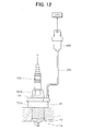
- An example in which the present invention is applied to a spark plug 700 is shown in FIG. 12, and an example in which the present invention is applied to a bolt 800 is shown in FIG. 13.
- the spark plug (referred to as structure in the present invention) 700 is attached to a screw hole 1b of an engine head 1 of a gasoline engine by means of a fixing screw (screw portion of the structure) 701a formed on the outer peripheral surface of the housing 701.
- the bolt referred to as the structure in the present invention
- the structure in the present invention that is a member exposed into a combustion chamber 1a in an engine head 1 is attached to a screw hole 1b of the engine head 1 by means of a fixing screw (screw portion of the structure) 801a formed on the outer peripheral surface of the engine head 1.
- the outside diameter of the hexagonal portions (referred to as nut portion in the present invention) 701b and 801b side of the respective structures 700 and 800 is made smaller than the inside diameter of the through hole 31a of the combustion pressure sensor 31.
- the respective structures 700 and 800 are can be inserted into the through hole 31a of the combustion pressure sensor 31 from the hexagonal portion side end.
- the examples exhibit the same effect as obtained in the above-mentioned first embodiment.
- the above-mentioned second and third embodiments and other embodiments can be applied to these examples.
- the present invention is also applied to an injector that is to be attached to an engine, though it is not shown in the drawing.
- the shape of the nut portion of the present invention is by no means limited to the above-mentioned hexagonal portions 201b, 221, 701b, and 801b that are all hexagonal, but any shape such as triangle, rectangle, square, or octagon may be employed as long as the shape is sufficiently effective to give the rotational force round the axis so that the structure is screw-connected to the screw hole 1b.
- the present invention provides a glow plug with combustion pressure sensor (100) having a plug body (220) having a screw portion (201a) on the outer peripheral surface that is inserted into a screw hole (1b) of an engine head (1) and screw-connected to it, a combustion pressure sensor (31) fixed to the plug body (220) to which the plug body (220) is inserted, and a lead wire (500) for leading out the sensor signal connected to the sensor (31), wherein the outside diameter of a hexagonal portion (221) used for screw connection between the plug body (220) and the screw hole (1b) out of the plug body (220) is smaller than the inside diameter of a through hole (31a) of the combustion pressure sensor (31) so that the plug body (220) can be inserted into the combustion pressure sensor (31) from the hexagonal portion (221) end.
Landscapes
- Chemical & Material Sciences (AREA)
- Engineering & Computer Science (AREA)
- Combustion & Propulsion (AREA)
- Physics & Mathematics (AREA)
- General Physics & Mathematics (AREA)
- Measuring Fluid Pressure (AREA)
- Ignition Installations For Internal Combustion Engines (AREA)
Abstract
Description
Claims (10)
- A combustion pressure sensor characterized in that:wherein the second end of the combustion pressure sensor has a nut portion formed thereon, an outer diameter including the nut portion of the second end is smaller than an inside diameter of the through hole of the combustion pressure sensor, the structure being inserted into the through hole of the combustion pressure sensor from the second end of the structure.a structure (220, 700, 800) having a first end and a second end, said first end inserted into a screw hole (1b) formed in an engine, said second end having a screw portion (201a, 701a, 801a) that screw connects said structure to an inside peripheral surface of said screw hole, said structure having a nut portion (221, 701b, 801b) for providing rotational force round an axis of said structure to screw connect the second end of said structure to said inside peripheral surface of said screw hole;a combustion pressure sensor (31 to 37) having a through hole (31a to 37a) through which the structure is inserted for detecting combustion pressure of the engine; anda lead wire (305, 500) that carries an outputted signal from the combustion pressure sensor to an external receiving area;wherein the combustion pressure sensor is attached to the structure by inserting the structure into a through hole on the combustion pressure sensor to attach the combustion pressure sensor to the structure; and
- The combustion pressure sensor according to claim 1, characterized in that a second screw portion (311) is formed on the inside surface of the through hole (31a, 33a, 34a) of the combustion pressure sensor (31, 33, 34), the structure (220, 700, 800) is inserted into the through hole, the screw portion (201a, 701a, 801a) of the structure is screw-connected to the screw portion of the through hole to thereby fix the combustion pressure sensor to the structure.
- A combustion pressure sensor characterized in that:a structure (200, 220, 700, 800) with a screw portion (201a, 701a, 801a) on an outer peripheral surface having one end inserted into a screw hole (1b) formed on an engine to screw-connect the structure to the screw hole by turning the structure round an axis of the structure;a combustion pressure sensor (33 to 35, 37) attached at a middle portion along the axis of the structure, said combustion pressure sensor for detecting a combustion pressure of the engine; anda lead wire (305, 500) that transports a signal from the combustion pressure sensor to an external area; andwherein the combustion pressure sensor has a lead wire detachably connected to the combustion pressure sensor.
- The combustion pressure sensor according to claim 3, characterized in that the lead wire (305, 500) is detachably connected to the combustion pressure sensor (33 to 35, 37) by a screw-connection.
- The combustion pressure sensor according to claim 3 or claim 4, characterized in that;a through hole (31a, 33a, 34a) having a screw portion (311) on an inside surface is formed on the combustion pressure sensor (31, 33, 34); andthe structure (200, 220, 700, 800) is inserted into the through hole, the screw portion (201a, 701a, 801a) of the structure is screw-connected to the screw portion of the through hole to thereby fix the combustion pressure sensor to the structure.
- A combustion pressure sensor characterized in that:a structure (200, 220, 700, 800) with a screw portion (201a, 701a, 801a) on an outer peripheral surface of the structure, said structure having a first end inserted into a screw hole (1b) formed on an engine, said structure screw-connected to the screw hole by rotation of said structure round an axis of the structure;a combustion pressure sensor (36, 37) attached on a middle portion along the axis of the structure, said combustion pressure sensor for detecting the combustion pressure of the engine; anda lead wire (305, 500) that outputs a signal from the combustion pressure sensor to an external area; andwherein the combustion pressure sensor has a cutout portion (36a, 37a) formed from an outer periphery to an inside area of the combustion pressure sensor, and the cutout portion is fitted to the structure.
- The combustion pressure sensor according to any one of claim 1, 3, 4, or 6, characterized in that the combustion pressure sensor (32, 35 to 37) is fixed to the structure by axial force of a separate nut (600), said nut being screw-connected to the screw portion (201a, 701a, 801a) of the structure (200, 220, 700, 800).
- The combustion pressure sensor according to claim 7, characterized in that the lead wire (305, 500) is connected to the combustion pressure sensor (32, 35 to 37) is drawn out from a direction different from an action direction of axial force of the nut (600).
- A method for assembling a combustion pressure sensor to an engine, said method characterized in that:inserting a structure having a first end and a second end into a screw hole formed in an engine;screwing said structure to threadenly engage said structure with said screw hole by applying rotational torque on a nut portion located at the second end of said structure; andpositioning a combustion pressure around said structure from said second end, said sensor having a through hole through which the structure is inserted;wherein an outer diameter including the nut portion of the second end is smaller than an inside diameter of the through hole of the combustion pressure sensor to allow said structure to be inserted into the through hole of the combustion pressure sensor from the second end of the structure.
- The method according to claim 9, characterized in that said positioning step comprises threadenly engaging an inside diameter of said through hole of said combustion sensor to said structure.
Priority Applications (1)
| Application Number | Priority Date | Filing Date | Title |
|---|---|---|---|
| EP08170506A EP2028470A3 (en) | 1999-12-24 | 2000-12-19 | Combustion pressure sensor |
Applications Claiming Priority (2)
| Application Number | Priority Date | Filing Date | Title |
|---|---|---|---|
| JP36645799A JP4003363B2 (en) | 1999-12-24 | 1999-12-24 | Combustion pressure sensor structure |
| JP36645799 | 1999-12-24 |
Related Child Applications (1)
| Application Number | Title | Priority Date | Filing Date |
|---|---|---|---|
| EP08170506A Division EP2028470A3 (en) | 1999-12-24 | 2000-12-19 | Combustion pressure sensor |
Publications (2)
| Publication Number | Publication Date |
|---|---|
| EP1111361A2 true EP1111361A2 (en) | 2001-06-27 |
| EP1111361A3 EP1111361A3 (en) | 2003-03-05 |
Family
ID=18486834
Family Applications (2)
| Application Number | Title | Priority Date | Filing Date |
|---|---|---|---|
| EP08170506A Withdrawn EP2028470A3 (en) | 1999-12-24 | 2000-12-19 | Combustion pressure sensor |
| EP00127800A Ceased EP1111361A3 (en) | 1999-12-24 | 2000-12-19 | Combustion pressure sensor |
Family Applications Before (1)
| Application Number | Title | Priority Date | Filing Date |
|---|---|---|---|
| EP08170506A Withdrawn EP2028470A3 (en) | 1999-12-24 | 2000-12-19 | Combustion pressure sensor |
Country Status (3)
| Country | Link |
|---|---|
| US (1) | US6575039B2 (en) |
| EP (2) | EP2028470A3 (en) |
| JP (1) | JP4003363B2 (en) |
Cited By (7)
| Publication number | Priority date | Publication date | Assignee | Title |
|---|---|---|---|---|
| EP1460403A1 (en) * | 2003-03-17 | 2004-09-22 | Ngk Spark Plug Co., Ltd. | Glow plug with built-in combustion pressure sensor |
| FR2855265A1 (en) * | 2003-05-23 | 2004-11-26 | Siemens Vdo Automotive | WATERPROOF CONNECTOR FOR PRESSURE SENSOR OF INTERNAL COMBUSTION ENGINE |
| EP1519175A1 (en) * | 2003-09-23 | 2005-03-30 | Beru AG | Pressure sensor plug |
| WO2005045319A1 (en) * | 2003-10-10 | 2005-05-19 | Robert Bosch Gmbh | Sheathed-type glow plug comprising an integrated pressure sensor |
| DE102004047143A1 (en) * | 2004-09-29 | 2006-04-06 | Robert Bosch Gmbh | Piezoelectric combustion chamber pressure sensor with a pressure transfer pin |
| EP2028470A2 (en) | 1999-12-24 | 2009-02-25 | Denso Corporation | Combustion pressure sensor |
| JP2014194388A (en) * | 2013-03-29 | 2014-10-09 | Fuji Koki Corp | Pressure sensor |
Families Citing this family (36)
| Publication number | Priority date | Publication date | Assignee | Title |
|---|---|---|---|---|
| JP3911930B2 (en) * | 1999-10-28 | 2007-05-09 | 株式会社デンソー | Glow plug with combustion pressure sensor |
| JP2004262276A (en) * | 2003-02-28 | 2004-09-24 | Murakami Corp | Wiring structure of car body exterior equipment |
| US6722927B1 (en) * | 2003-05-28 | 2004-04-20 | Rosemount Inc. | Electrical connector for a pressure sensor stem |
| EP1486653B1 (en) * | 2003-06-12 | 2016-04-13 | Denso Corporation | Combustion pressure sensor |
| DE10333438A1 (en) * | 2003-07-23 | 2005-02-17 | Robert Bosch Gmbh | Combustion chamber pressure sensor with metal diaphragm with piezoresistive metal thin film |
| DE10343521A1 (en) * | 2003-09-19 | 2005-04-21 | Beru Ag | Pressure measuring glow plug for a diesel engine |
| US7207214B1 (en) * | 2004-02-17 | 2007-04-24 | Wlodarczyk Marek T | Glow plug integrated pressure sensor |
| DE102004011098A1 (en) * | 2004-03-06 | 2005-09-22 | Robert Bosch Gmbh | Device for detecting the combustion chamber pressure in an internal combustion engine |
| FR2869394B1 (en) * | 2004-04-27 | 2006-07-14 | Siemens Vdo Automotive Sas | PREHEATING CANDLE HEAD AND CORRESPONDING PIEZOELECTRIC PRESSURE SENSOR |
| FR2869393B1 (en) * | 2004-04-27 | 2006-07-14 | Siemens Vdo Automotive Sas | DEVICE FOR ACTING ON A PRESSURE SENSOR MOUNTED ON A PREHEATING CANDLE |
| FR2869391B1 (en) * | 2004-04-27 | 2006-07-14 | Siemens Vdo Automotive Sas | PREHEATING CUP INCLUDING A PRESSURE SENSOR |
| JP4166736B2 (en) * | 2004-08-05 | 2008-10-15 | 本田技研工業株式会社 | Combustion pressure detector |
| US20060027013A1 (en) * | 2004-08-05 | 2006-02-09 | Honda Motor Co., Ltd. | Combustion pressure detecting apparatus |
| US7216531B2 (en) * | 2005-04-28 | 2007-05-15 | Spx Corporation | Compression tester adapter apparatus and method |
| US7214908B2 (en) * | 2005-07-28 | 2007-05-08 | Wlodarczyk Marek T | Glow plug integrated pressure sensor with filter trap |
| JP2008139150A (en) * | 2006-12-01 | 2008-06-19 | Denso Corp | Combustion pressure sensor |
| NL1033069C2 (en) * | 2006-12-15 | 2008-06-17 | Ind Bolting Technology And Sup | Device and method for tightening a nut turned on a threaded end and composite washer and nut for such a device. |
| JP5006695B2 (en) * | 2007-05-16 | 2012-08-22 | シチズンファインテックミヨタ株式会社 | Pressure sensor |
| JP4959509B2 (en) * | 2007-11-06 | 2012-06-27 | 株式会社デンソー | Fuel injection valve |
| JP4483955B2 (en) * | 2008-02-28 | 2010-06-16 | 株式会社デンソー | Engine head module |
| DE102008020509B4 (en) * | 2008-04-23 | 2010-02-25 | Beru Ag | Method for producing a device for determining the combustion chamber pressure and such a device |
| JP5654846B2 (en) * | 2010-01-22 | 2015-01-14 | 日本特殊陶業株式会社 | Combustion pressure sensor |
| EP2444786B1 (en) * | 2010-10-20 | 2013-07-17 | Sensata Technologies, Inc. | A pressure measuring glow plug for a combustion engine |
| JP5771400B2 (en) * | 2011-01-25 | 2015-08-26 | 日本特殊陶業株式会社 | Glow plug |
| DE102011088468A1 (en) * | 2011-12-14 | 2013-06-20 | Robert Bosch Gmbh | pressure measuring glow |
| KR20140094643A (en) * | 2011-12-26 | 2014-07-30 | 니혼도꾸슈도교 가부시키가이샤 | Ceramic glow plug equipped with pressure sensor |
| WO2013137432A1 (en) * | 2012-03-16 | 2013-09-19 | シチズンファインテックミヨタ株式会社 | Internal combustion engine fitted with combustion pressure detection device, and combustion pressure detection device |
| JP6151067B2 (en) * | 2012-06-28 | 2017-06-21 | 日本特殊陶業株式会社 | Glow plug with pressure sensor |
| US9841356B2 (en) * | 2012-08-29 | 2017-12-12 | Citizen Finedevice Co., Ltd. | Combustion pressure sensor |
| MX353787B (en) * | 2013-02-11 | 2018-01-29 | Contour Hardening Inc | Combustion ignition system. |
| WO2015066310A1 (en) * | 2013-10-30 | 2015-05-07 | Lime Instruments Llc | Sensor assembly for measuring dynamic pressure in reciprocating pumps |
| US9483674B1 (en) | 2014-03-07 | 2016-11-01 | United States Of America As Represented By The Administrator Of The National Aeronautics And Space Administration | RFID torque sensing tag system for fasteners |
| US9644532B2 (en) * | 2015-04-14 | 2017-05-09 | Sheldon J. Demmons | Autonomous glow driver for radio controlled engines |
| US9657707B2 (en) | 2015-04-14 | 2017-05-23 | Sheldon J. Demmons | Autonomous glow driver for radio controlled engines |
| US10527523B2 (en) * | 2015-12-18 | 2020-01-07 | Ge Global Sourcing Llc | Vehicle sensor assembly having an RF sensor disposed in the sensor assembly to wirelessly communicate data to outside the sensor assembly |
| EP4556872B1 (en) * | 2023-11-15 | 2026-08-05 | Kistler Holding AG | Pressure sensor and method for the production thereof |
Family Cites Families (14)
| Publication number | Priority date | Publication date | Assignee | Title |
|---|---|---|---|---|
| DE1590923A1 (en) * | 1966-07-25 | 1971-02-18 | Rft Messelektronik Dresden Veb | Electrical connector with flange-like attachment and screw cap |
| EP0013702A1 (en) * | 1978-11-14 | 1980-08-06 | Creative Tool Company Corp. | Transducer device for monitoring pressure |
| DE3122375C2 (en) * | 1981-06-05 | 1983-03-03 | Robert Bosch Gmbh, 7000 Stuttgart | Sensor arrangement |
| JPS5960237A (en) * | 1982-09-30 | 1984-04-06 | Nippon Soken Inc | Glow plug with built-in internal pressure detector |
| JPS59145927A (en) * | 1983-02-09 | 1984-08-21 | Matsushita Electric Ind Co Ltd | Knock sensor |
| DE3320332C1 (en) | 1983-06-04 | 1988-07-07 | Deere & Co., Moline, Ill., US, Niederlassung Deere & Co. European Office, 6800 Mannheim | Method of loading a container with vehicles |
| JPS60133338A (en) * | 1983-12-22 | 1985-07-16 | Nippon Denso Co Ltd | Pressure detector of internal-combustion engine |
| DE3445452A1 (en) * | 1984-12-13 | 1986-06-19 | Robert Bosch Gmbh, 7000 Stuttgart | KNOCK SENSOR |
| JPH07139736A (en) * | 1993-11-16 | 1995-05-30 | Nippondenso Co Ltd | Glow plug with combustion pressure sensor |
| JPH08232823A (en) | 1995-02-22 | 1996-09-10 | Unisia Jecs Corp | Ignition device |
| JPH08232825A (en) | 1995-02-22 | 1996-09-10 | Unisia Jecs Corp | Ignition device with integrated combustion pressure sensor |
| JP3177819B2 (en) * | 1995-09-05 | 2001-06-18 | 株式会社ユニシアジェックス | In-cylinder pressure detector for internal combustion engines |
| JP3870454B2 (en) | 1996-10-04 | 2007-01-17 | 株式会社デンソー | Glow plug |
| JP4003363B2 (en) | 1999-12-24 | 2007-11-07 | 株式会社デンソー | Combustion pressure sensor structure |
-
1999
- 1999-12-24 JP JP36645799A patent/JP4003363B2/en not_active Expired - Fee Related
-
2000
- 2000-12-19 EP EP08170506A patent/EP2028470A3/en not_active Withdrawn
- 2000-12-19 EP EP00127800A patent/EP1111361A3/en not_active Ceased
- 2000-12-22 US US09/742,000 patent/US6575039B2/en not_active Expired - Fee Related
Cited By (7)
| Publication number | Priority date | Publication date | Assignee | Title |
|---|---|---|---|---|
| EP2028470A2 (en) | 1999-12-24 | 2009-02-25 | Denso Corporation | Combustion pressure sensor |
| EP1460403A1 (en) * | 2003-03-17 | 2004-09-22 | Ngk Spark Plug Co., Ltd. | Glow plug with built-in combustion pressure sensor |
| FR2855265A1 (en) * | 2003-05-23 | 2004-11-26 | Siemens Vdo Automotive | WATERPROOF CONNECTOR FOR PRESSURE SENSOR OF INTERNAL COMBUSTION ENGINE |
| EP1519175A1 (en) * | 2003-09-23 | 2005-03-30 | Beru AG | Pressure sensor plug |
| WO2005045319A1 (en) * | 2003-10-10 | 2005-05-19 | Robert Bosch Gmbh | Sheathed-type glow plug comprising an integrated pressure sensor |
| DE102004047143A1 (en) * | 2004-09-29 | 2006-04-06 | Robert Bosch Gmbh | Piezoelectric combustion chamber pressure sensor with a pressure transfer pin |
| JP2014194388A (en) * | 2013-03-29 | 2014-10-09 | Fuji Koki Corp | Pressure sensor |
Also Published As
| Publication number | Publication date |
|---|---|
| EP2028470A3 (en) | 2009-05-13 |
| EP2028470A2 (en) | 2009-02-25 |
| JP2001182585A (en) | 2001-07-06 |
| EP1111361A3 (en) | 2003-03-05 |
| US6575039B2 (en) | 2003-06-10 |
| JP4003363B2 (en) | 2007-11-07 |
| US20010008090A1 (en) | 2001-07-19 |
Similar Documents
| Publication | Publication Date | Title |
|---|---|---|
| US6575039B2 (en) | Combustion pressure sensor assembly | |
| JP4300663B2 (en) | Combustion pressure sensor structure | |
| JP3885515B2 (en) | Glow plug with combustion pressure sensor | |
| JP3942176B2 (en) | Glow plug with combustion pressure detection function and manufacturing method thereof | |
| EP1486653B1 (en) | Combustion pressure sensor | |
| JP3911930B2 (en) | Glow plug with combustion pressure sensor | |
| EP1460403A1 (en) | Glow plug with built-in combustion pressure sensor | |
| US5852280A (en) | Ceramic heater | |
| JP4316474B2 (en) | Combustion chamber pressure detector | |
| JP4407044B2 (en) | Combustion pressure sensor structure | |
| JP2003077620A (en) | Spark plug and manufacturing method thereof | |
| JP2006307834A (en) | Combustion pressure sensor and glow plug provided with the same | |
| JP2004163091A (en) | Glow plug with combustion pressure sensor | |
| JP2005207721A (en) | Glow plug | |
| JP2002124362A (en) | Spark plug with built-in pressure sensor | |
| EP1096140B1 (en) | Attachment structure of glow plug | |
| EP1351356A2 (en) | Ignition device for an internal combustion engine | |
| JP4206941B2 (en) | Combustion pressure sensor | |
| JP4177342B2 (en) | Glow plug with combustion pressure detection mechanism and method for manufacturing glow plug with combustion pressure detection function | |
| JP2006284396A (en) | Combustion pressure sensor and glow plug provided with the same | |
| JP2002013735A (en) | Glow plug | |
| JP2007053074A (en) | Spark plug with pressure detection function, voltage supply component for spark plug and ignition coil integrated with plug with pressure detection function | |
| JPH07113714A (en) | Piezoelectric pressure sensor | |
| JP4268596B2 (en) | Glow plug with combustion pressure detection mechanism and glow plug connection structure | |
| JP2006284011A (en) | Glow plug with combustion pressure sensor |
Legal Events
| Date | Code | Title | Description |
|---|---|---|---|
| PUAI | Public reference made under article 153(3) epc to a published international application that has entered the european phase |
Free format text: ORIGINAL CODE: 0009012 |
|
| AK | Designated contracting states |
Kind code of ref document: A2 Designated state(s): AT BE CH CY DE DK ES FI FR GB GR IE IT LI LU MC NL PT SE TR |
|
| AX | Request for extension of the european patent |
Free format text: AL;LT;LV;MK;RO;SI |
|
| PUAL | Search report despatched |
Free format text: ORIGINAL CODE: 0009013 |
|
| AK | Designated contracting states |
Kind code of ref document: A3 Designated state(s): AT BE CH CY DE DK ES FI FR GB GR IE IT LI LU MC NL PT SE TR Designated state(s): AT BE CH CY DE DK ES FI FR GB GR IE IT LI LU MC NL PT SE TR |
|
| AX | Request for extension of the european patent |
Extension state: AL LT LV MK RO SI |
|
| 17P | Request for examination filed |
Effective date: 20030410 |
|
| 17Q | First examination report despatched |
Effective date: 20030516 |
|
| AKX | Designation fees paid |
Designated state(s): DE FR GB |
|
| STAA | Information on the status of an ep patent application or granted ep patent |
Free format text: STATUS: THE APPLICATION HAS BEEN REFUSED |
|
| 18R | Application refused |
Effective date: 20081203 |