EP1111287B1 - High temperature rotating union - Google Patents
High temperature rotating union Download PDFInfo
- Publication number
- EP1111287B1 EP1111287B1 EP00309189A EP00309189A EP1111287B1 EP 1111287 B1 EP1111287 B1 EP 1111287B1 EP 00309189 A EP00309189 A EP 00309189A EP 00309189 A EP00309189 A EP 00309189A EP 1111287 B1 EP1111287 B1 EP 1111287B1
- Authority
- EP
- European Patent Office
- Prior art keywords
- rotor
- rotating
- housing
- union
- seal member
- Prior art date
- Legal status (The legal status is an assumption and is not a legal conclusion. Google has not performed a legal analysis and makes no representation as to the accuracy of the status listed.)
- Expired - Lifetime
Links
- 239000002826 coolant Substances 0.000 claims abstract description 15
- 239000012530 fluid Substances 0.000 claims abstract description 11
- 238000007789 sealing Methods 0.000 claims abstract description 8
- 230000008878 coupling Effects 0.000 claims abstract description 6
- 238000010168 coupling process Methods 0.000 claims abstract description 6
- 238000005859 coupling reaction Methods 0.000 claims abstract description 6
- 230000007935 neutral effect Effects 0.000 claims description 4
- 230000003647 oxidation Effects 0.000 claims description 3
- 238000007254 oxidation reaction Methods 0.000 claims description 3
- 238000001816 cooling Methods 0.000 description 8
- 230000000712 assembly Effects 0.000 description 7
- 238000000429 assembly Methods 0.000 description 7
- OKTJSMMVPCPJKN-UHFFFAOYSA-N Carbon Chemical compound [C] OKTJSMMVPCPJKN-UHFFFAOYSA-N 0.000 description 4
- 229910052799 carbon Inorganic materials 0.000 description 4
- 230000009977 dual effect Effects 0.000 description 3
- 239000007789 gas Substances 0.000 description 3
- 239000000314 lubricant Substances 0.000 description 3
- IJGRMHOSHXDMSA-UHFFFAOYSA-N Atomic nitrogen Chemical compound N#N IJGRMHOSHXDMSA-UHFFFAOYSA-N 0.000 description 2
- 239000000463 material Substances 0.000 description 2
- 238000003490 calendering Methods 0.000 description 1
- 230000007613 environmental effect Effects 0.000 description 1
- 239000004519 grease Substances 0.000 description 1
- 238000002347 injection Methods 0.000 description 1
- 239000007924 injection Substances 0.000 description 1
- 229910052757 nitrogen Inorganic materials 0.000 description 1
- 239000000123 paper Substances 0.000 description 1
- 239000004033 plastic Substances 0.000 description 1
- 229920003023 plastic Polymers 0.000 description 1
- 238000005096 rolling process Methods 0.000 description 1
- 239000004753 textile Substances 0.000 description 1
- XLYOFNOQVPJJNP-UHFFFAOYSA-N water Substances O XLYOFNOQVPJJNP-UHFFFAOYSA-N 0.000 description 1
Images


Classifications
-
- F—MECHANICAL ENGINEERING; LIGHTING; HEATING; WEAPONS; BLASTING
- F16—ENGINEERING ELEMENTS AND UNITS; GENERAL MEASURES FOR PRODUCING AND MAINTAINING EFFECTIVE FUNCTIONING OF MACHINES OR INSTALLATIONS; THERMAL INSULATION IN GENERAL
- F16C—SHAFTS; FLEXIBLE SHAFTS; ELEMENTS OR CRANKSHAFT MECHANISMS; ROTARY BODIES OTHER THAN GEARING ELEMENTS; BEARINGS
- F16C37/00—Cooling of bearings
- F16C37/007—Cooling of bearings of rolling bearings
-
- F—MECHANICAL ENGINEERING; LIGHTING; HEATING; WEAPONS; BLASTING
- F16—ENGINEERING ELEMENTS AND UNITS; GENERAL MEASURES FOR PRODUCING AND MAINTAINING EFFECTIVE FUNCTIONING OF MACHINES OR INSTALLATIONS; THERMAL INSULATION IN GENERAL
- F16C—SHAFTS; FLEXIBLE SHAFTS; ELEMENTS OR CRANKSHAFT MECHANISMS; ROTARY BODIES OTHER THAN GEARING ELEMENTS; BEARINGS
- F16C19/00—Bearings with rolling contact, for exclusively rotary movement
- F16C19/22—Bearings with rolling contact, for exclusively rotary movement with bearing rollers essentially of the same size in one or more circular rows, e.g. needle bearings
- F16C19/34—Bearings with rolling contact, for exclusively rotary movement with bearing rollers essentially of the same size in one or more circular rows, e.g. needle bearings for both radial and axial load
- F16C19/36—Bearings with rolling contact, for exclusively rotary movement with bearing rollers essentially of the same size in one or more circular rows, e.g. needle bearings for both radial and axial load with a single row of rollers
- F16C19/361—Bearings with rolling contact, for exclusively rotary movement with bearing rollers essentially of the same size in one or more circular rows, e.g. needle bearings for both radial and axial load with a single row of rollers with cylindrical rollers
- F16C19/362—Bearings with rolling contact, for exclusively rotary movement with bearing rollers essentially of the same size in one or more circular rows, e.g. needle bearings for both radial and axial load with a single row of rollers with cylindrical rollers the rollers being crossed within the single row
-
- Y—GENERAL TAGGING OF NEW TECHNOLOGICAL DEVELOPMENTS; GENERAL TAGGING OF CROSS-SECTIONAL TECHNOLOGIES SPANNING OVER SEVERAL SECTIONS OF THE IPC; TECHNICAL SUBJECTS COVERED BY FORMER USPC CROSS-REFERENCE ART COLLECTIONS [XRACs] AND DIGESTS
- Y10—TECHNICAL SUBJECTS COVERED BY FORMER USPC
- Y10T—TECHNICAL SUBJECTS COVERED BY FORMER US CLASSIFICATION
- Y10T137/00—Fluid handling
- Y10T137/6416—With heating or cooling of the system
- Y10T137/6525—Air heated or cooled [fan, fins, or channels]
-
- Y—GENERAL TAGGING OF NEW TECHNOLOGICAL DEVELOPMENTS; GENERAL TAGGING OF CROSS-SECTIONAL TECHNOLOGIES SPANNING OVER SEVERAL SECTIONS OF THE IPC; TECHNICAL SUBJECTS COVERED BY FORMER USPC CROSS-REFERENCE ART COLLECTIONS [XRACs] AND DIGESTS
- Y10—TECHNICAL SUBJECTS COVERED BY FORMER USPC
- Y10T—TECHNICAL SUBJECTS COVERED BY FORMER US CLASSIFICATION
- Y10T137/00—Fluid handling
- Y10T137/6416—With heating or cooling of the system
- Y10T137/6579—Circulating fluid in heat exchange relationship
-
- Y—GENERAL TAGGING OF NEW TECHNOLOGICAL DEVELOPMENTS; GENERAL TAGGING OF CROSS-SECTIONAL TECHNOLOGIES SPANNING OVER SEVERAL SECTIONS OF THE IPC; TECHNICAL SUBJECTS COVERED BY FORMER USPC CROSS-REFERENCE ART COLLECTIONS [XRACs] AND DIGESTS
- Y10—TECHNICAL SUBJECTS COVERED BY FORMER USPC
- Y10T—TECHNICAL SUBJECTS COVERED BY FORMER US CLASSIFICATION
- Y10T137/00—Fluid handling
- Y10T137/8593—Systems
- Y10T137/86268—With running joint between movable parts of system
Definitions
- the present invention relates to rotating union coupling devices which have particular application in high temperature environments employing steam, hot water and hot oil applications.
- Rotating unions have been used extensively in the paper, plastics and textile processing industries to couple the outlet of a fluid source to rotating drums or cylindrical rolls or to open gear paper machines.
- the rotary unions utilize either carbon journal bearings or dual ball bearing structures to absorb and maintain the alignment of the rotor and the load of the joint assembly.
- ball bearing assemblies are limited to a maximum temperature range of about 125°C because of the thermal instability of the standard bearing materials above such temperatures.
- the ball bearing assembly when ball bearings assemblies are utilized as the rolling bearing structure within a rotary union, the ball bearing assembly must be grease lubricated which effectively limits the use of such bearing structures to application temperatures dictated by the bearing temperature limitations.
- such ball bearing assemblies can be lubricated by the heat transfer oil, which is a relatively poor lubricant, and require that the assembly include at least dual bearing structures to provide support for the rotating rotor in the rotating union.
- the rotary joint or union assembly includes a cylindrical housing, an end cap or head member, a tubular rotor member, a rotor bearing assembly and a mechanical face seal assembly comprised of a rotating seal member secured to the end of the tubular rotor and a non-rotating seal member mounted to a carrier or sleeve member axially moveable and positioned within the housing.
- the tubular rotor is mounted within the housing and is maintained in axial alignment with the non-rotating seal member by a rotor bearing assembly comprised of a single special bearing structure or portion in a non-heat stabilized condition and seated in a counterbore in the housing.
- the outer race member portion of the bearing structure or assembly is secured to the housing and the inner race member portion of the bearing assembly is secured to a shoulder of the rotor member.
- the tubular rotor member includes cooling means which includes a circumferential recess extending therearound and positioned to the rotor wall.
- the circumferential recess is radially surrounded and enclosed by an annular sealing or insulating member to define and provide an air pocket or chamber between the rotor and the annular sealing member to insulate the bearing structure from the hot fluid flowing through the rotor.
- the cooling means include a plurality of fins radially extending outwardly from the rotor which impel and facilitate air circulation around and past the bearing assembly thereby maintaining the bearing temperature within acceptable levels of about 120°C or less without externally supplied cooling. Such cooling means permits the use of non-heat stabilized bearings in the bearing assembly.
- the radial and axial position and location of the bearing assembly within the cylindrical housing optimizes the bearing efficiency by minimizing the bearing operating temperatures during operation of the rotating assembly.
- the bearing assembly includes a single special bearing structure which does not require the bearing to be lubricated by a heat transfer oil, which is a relatively poor lubricant. Also, the bearing structure, because of its axial position within the housing with respect to the rotating rotor, handles both the radial and axial loads of the rotating rotor and provides improved tilting support in all directions of the rotor. Accordingly, the single special bearing structure provides a much higher load and speed capacity than carbon journal type bearings while being substantially more compact thereby requiring less space than dual ball bearing structures, as used in the prior art structures, e.g. US 5,156,523.
- the rotating union assembly 10 includes a cylindrical housing 12, an end cap or head member 14, a tubular rotor member 11, a rotor bearing assembly 30 and a mechanical face seal assembly 18.
- the mechanical face seal assembly 18 is comprised of a rotating face seal member 20 secured to the end lla of the tubular rotor 11 and a second non-rotating seal means or member 22 mounted to a tubular carrier member or sleeve assembly 24 which is axially moveable within the housing 12 between a first position wherein the second seal member is spaced from the first seal member and a second position wherein the second seal member and the first seal member are engaged together to provide a seal between the rotor and the carrier.
- the tubular rotor 11 has an axial discharge bore or passageway 17 therethrough.
- the rotor bearing assembly 30 includes a single special bearing assembly 32, such as a cross-cylindrical roller bearing assembly, positioned in a non-heat stabilized condition and seated in a counterbore in the housing 12 surrounding the inner stem portion llb of the rotor 11.
- the outer race member portion 34 of the bearing assembly 30 is secured to the housing 12 and the inner race member portion 36 of the bearing assembly is structurally arranged to cooperate with shoulder 25 on the rotor member 11 to support rotation of the rotor.
- the housing 12 or end cap or head member 14 includes flange portions 26 thereon for operatively connecting the union for supply and removal of the conveyed medium, as is known in the art.
- a duo-flow union assembly is illustrated having first and second ports 28 and 29, respectively; and as shown in FIGS. 4 and 5, a monoflow union assembly is illustrated having a single port 28.
- the tubular rotor member 11 includes an insulating air gap or pocket 40 extending therearound.
- the air pocket 40 is defined by a recess 42 in the outer rotor wall 13 and positioned in a recess of the rotor wall 13 which is radially surrounded and sealed by an insulating member 44.
- the gap or air pocket 40 insulates the bearing assembly from the hot fluid flowing through the rotor discharge passageway 17 of the rotor 11. As shown in FIG.
- the rotor 11 includes also a plurality of fins 46 equally spaced about the rotor and radially extending outwardly from the rotor which impels and facilitates air circulation around and past the bearing assembly 30 thereby maintaining the bearing temperature within acceptable levels of about 120°C or less without the need of externally supplied cooling.
- the number of fins 46 are shown radially extending outwardly from the rotor.
- the number of fins may vary, e.g. there may be six fins, so long as the fins are spaced equally about the rotor in a balanced fashion.
- the air cooling resulting from the fin rotation directs the air coolant through the gaps 57 between the fins 46 to cool the bearing assembly and permits the use of non-heat stabilized bearings in the bearing assembly.
- the radial and axial position and location of the bearing assembly 30 within the cylindrical housing 12 optimizes the bearing efficiency by minimizing the bearing operating temperatures during operation of the rotating union or joint assembly.
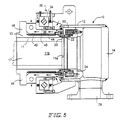
- the operating conditions of the duoflow rotating joint 10 (FIG. 3) and the monoflow rotating joint assembly 10 (FIG. 5) permit the flow of air coolant around the bearing assembly 30, as shown by the arrows in FIGS. 3 and 5.
- the rotating union may include an annular channel 54 structurally arranged around the rotor 11 to direct air coolant from a blower 56 through the gaps 57 between the fins 46 to facilitate cooling of the bearing housing. This is shown by the arrows in FIGS. 1 and 4.
- the unique design of the present rotating union utilizes a rotating seal member 20 mounted to the end lla of the tubular rotor to provide a mechanical seal in conjunction with the non-rotating seal member 22 mounted to carrier assembly 24.
- the non-rotating seal member 22 is positioned in tandem with a separately mounted spring biased retaining member 23 which permits the non-rotating seal to float thereby minimizing seal face distortions from thermal gradients during operation of the rotating union assembly 10.
- the cylindrical housing includes ports 50 therein which communicate with the cavity 52 surrounding the mechanical seal of the coolant union.
- the ports permit the injection of neutral buffer gases, such as nitrogen, to be directed through the ports 50 into the cavity 52 to eliminate oxidation of hot leaked oil that may escape from the mechanical seal face assembly 18.
- neutral buffer gases provides for the control of any seal leakage of the mechanical face seal and provides excellent environmental protection and minimizes human exposure to the pumped fluids.
- a single special bearing structure is desired because such a bearing structure does not require the bearing design to be lubricated by a heat transfer oil which is a relatively poor lubricant. Accordingly, utilization of an insulating air pocket and associated fin structure provides excellent air circulation about the bearing assembly and maintains the bearing assembly temperature within acceptable operational levels.
- the single bearing structure because of its axial position and location within the housing with respect to the rotating rotor, handles both the radial and axial loads of the rotating rotor and provides improved support in all directions of the rotor.
- the special bearing design provides also a much higher load and speed capacity than carbon journal type bearings while being substantially more compact thereby requiring less space than a pair of journal ball bearings, as commonly used in the prior art structures.
Landscapes
- General Engineering & Computer Science (AREA)
- Engineering & Computer Science (AREA)
- Mechanical Engineering (AREA)
- Joints Allowing Movement (AREA)
- Mounting Of Bearings Or Others (AREA)
- Rolling Contact Bearings (AREA)
- Treatment Of Fiber Materials (AREA)
- Paper (AREA)
- Sliding-Contact Bearings (AREA)
- Sealing Of Bearings (AREA)
- Quick-Acting Or Multi-Walled Pipe Joints (AREA)
- Pivots And Pivotal Connections (AREA)
- Flanged Joints, Insulating Joints, And Other Joints (AREA)
- Mechanical Sealing (AREA)
Abstract
Description
- The present invention relates to rotating union coupling devices which have particular application in high temperature environments employing steam, hot water and hot oil applications.
- Rotating unions have been used extensively in the paper, plastics and textile processing industries to couple the outlet of a fluid source to rotating drums or cylindrical rolls or to open gear paper machines. In known rotary unions utilized in coupling fluid sources to such rotating devices, the rotary unions utilize either carbon journal bearings or dual ball bearing structures to absorb and maintain the alignment of the rotor and the load of the joint assembly. However, such ball bearing assemblies are limited to a maximum temperature range of about 125°C because of the thermal instability of the standard bearing materials above such temperatures. Also, when ball bearings assemblies are utilized as the rolling bearing structure within a rotary union, the ball bearing assembly must be grease lubricated which effectively limits the use of such bearing structures to application temperatures dictated by the bearing temperature limitations. Additionally, such ball bearing assemblies can be lubricated by the heat transfer oil, which is a relatively poor lubricant, and require that the assembly include at least dual bearing structures to provide support for the rotating rotor in the rotating union.
- Another use of ball bearing structures in rotary union assemblies requires multiple seal assemblies and external buffer systems to maintain the thermal stability of the carbon bearing materials. Accordingly, such bearing structures are expensive and space consuming. Thus, when it is desired to provide rotating union assemblies capable of use at high temperatures and which include a simplified structure, such bearing assemblies have found limited application.
- It is one object of the present invention to provide a rotary union assembly utilizing a single special bearing portion structurally arranged to withstand axial, radial and tilting loads on the assembly.
- It is an object of the present invention to provide a rotary union assembly utilizing a single cross-cylindrical roller bearing or a single four point contact ball bearing structurally arranged to withstand axial, radial and tilting loads on the assembly.
- It is another object of the present invention to provide a rotary union assembly having an insulating air pocket within the rotating rotor to provide and facilitate the cooling of the bearing assembly portion of the rotary union assembly.
- It is a further object of the present invention to provide a rotary union assembly having structural fins integral and structurally arranged on the rotating rotor which facilitates air circulation to the bearing structure or portion of the rotary union to thereby minimize and maintain the bearing temperature within the operating conditions of the bearing structure.
- It is yet another object of the present invention to provide a rotary union assembly having a radially and axially positioned bearing assembly which is spaced from the rotor to minimize the transfer of heat from the rotor union to the bearing assembly.
- It is also another object of the present invention to provide a rotary union having a mechanical face seal assembly.
- It is still another object of the present invention to provide a rotary union assembly having neutral buffer gas ports operatively associated with the mechanical face seal assembly to eliminate oxidation of the hot leaked oil from the mechanical face seal.
- These objects are attained by the rotating union of claims 1 and 6.
- In one embodiment of the present invention, the rotary joint or union assembly includes a cylindrical housing, an end cap or head member, a tubular rotor member, a rotor bearing assembly and a mechanical face seal assembly comprised of a rotating seal member secured to the end of the tubular rotor and a non-rotating seal member mounted to a carrier or sleeve member axially moveable and positioned within the housing. The tubular rotor is mounted within the housing and is maintained in axial alignment with the non-rotating seal member by a rotor bearing assembly comprised of a single special bearing structure or portion in a non-heat stabilized condition and seated in a counterbore in the housing. The outer race member portion of the bearing structure or assembly is secured to the housing and the inner race member portion of the bearing assembly is secured to a shoulder of the rotor member.
- The tubular rotor member includes cooling means which includes a circumferential recess extending therearound and positioned to the rotor wall. The circumferential recess is radially surrounded and enclosed by an annular sealing or insulating member to define and provide an air pocket or chamber between the rotor and the annular sealing member to insulate the bearing structure from the hot fluid flowing through the rotor. Also, the cooling means include a plurality of fins radially extending outwardly from the rotor which impel and facilitate air circulation around and past the bearing assembly thereby maintaining the bearing temperature within acceptable levels of about 120°C or less without externally supplied cooling. Such cooling means permits the use of non-heat stabilized bearings in the bearing assembly.
- The radial and axial position and location of the bearing assembly within the cylindrical housing optimizes the bearing efficiency by minimizing the bearing operating temperatures during operation of the rotating assembly. The bearing assembly includes a single special bearing structure which does not require the bearing to be lubricated by a heat transfer oil, which is a relatively poor lubricant. Also, the bearing structure, because of its axial position within the housing with respect to the rotating rotor, handles both the radial and axial loads of the rotating rotor and provides improved tilting support in all directions of the rotor. Accordingly, the single special bearing structure provides a much higher load and speed capacity than carbon journal type bearings while being substantially more compact thereby requiring less space than dual ball bearing structures, as used in the prior art structures, e.g. US 5,156,523.
- The forgoing description and other characteristics, objects, features and advantages of the present invention will become more apparent upon consideration of the following detailed description, having reference to the accompanying drawings wherein:
- FIG. 1 is a cross-sectional view of a duoflow rotating joint assembly in accordance with one embodiment of the present invention utilizing the inventive concepts in assembled operative relationship;
- FIG. 2 is a view taken along lines 2-2 of FIG. 1;
- FIG. 3 is a cross-sectional view of a duoflow rotating joint assembly in accordance with a further embodiment of the present invention utilizing the inventive concepts in assembled operative relationship;
- FIG. 4 is a cross-sectional view of a monoflow rotating joint assembly in accordance with the embodiment shown in FIG. 1 utilizing the inventive concepts in assembled operative relationship; and
- FIG. 5 is a cross-sectional view of a monoflow rotating joint assembly in accordance with the embodiment shown in FIG. 3 utilizing the inventive concepts in assembled operative relationship.
-
- Referring to FIG. 1, there is illustrated a duoflow rotating union or
joint assembly 10 which is designed for coupling a fluid source to a rotating drum or a calendaring roller (not shown). Therotating union assembly 10 includes acylindrical housing 12, an end cap orhead member 14, atubular rotor member 11, arotor bearing assembly 30 and a mechanicalface seal assembly 18. The mechanicalface seal assembly 18 is comprised of a rotatingface seal member 20 secured to the end lla of thetubular rotor 11 and a second non-rotating seal means ormember 22 mounted to a tubular carrier member orsleeve assembly 24 which is axially moveable within thehousing 12 between a first position wherein the second seal member is spaced from the first seal member and a second position wherein the second seal member and the first seal member are engaged together to provide a seal between the rotor and the carrier. Thetubular rotor 11 has an axial discharge bore orpassageway 17 therethrough. - The
rotor bearing assembly 30 includes a singlespecial bearing assembly 32, such as a cross-cylindrical roller bearing assembly, positioned in a non-heat stabilized condition and seated in a counterbore in thehousing 12 surrounding the inner stem portion llb of therotor 11. The outerrace member portion 34 of thebearing assembly 30 is secured to thehousing 12 and the innerrace member portion 36 of the bearing assembly is structurally arranged to cooperate withshoulder 25 on therotor member 11 to support rotation of the rotor. - The
housing 12 or end cap orhead member 14 includesflange portions 26 thereon for operatively connecting the union for supply and removal of the conveyed medium, as is known in the art. As shown in FIGS. 1 and 3, a duo-flow union assembly is illustrated having first andsecond ports single port 28. - In accordance with the present invention, the
tubular rotor member 11 includes an insulating air gap orpocket 40 extending therearound. Theair pocket 40 is defined by arecess 42 in theouter rotor wall 13 and positioned in a recess of therotor wall 13 which is radially surrounded and sealed by aninsulating member 44. The gap orair pocket 40 insulates the bearing assembly from the hot fluid flowing through therotor discharge passageway 17 of therotor 11. As shown in FIG. 2, therotor 11 includes also a plurality offins 46 equally spaced about the rotor and radially extending outwardly from the rotor which impels and facilitates air circulation around and past thebearing assembly 30 thereby maintaining the bearing temperature within acceptable levels of about 120°C or less without the need of externally supplied cooling. - As shown in FIG. 2, in one embodiment of the present invention, eight
fins 46 are shown radially extending outwardly from the rotor. However, the number of fins may vary, e.g. there may be six fins, so long as the fins are spaced equally about the rotor in a balanced fashion. The air cooling resulting from the fin rotation directs the air coolant through thegaps 57 between thefins 46 to cool the bearing assembly and permits the use of non-heat stabilized bearings in the bearing assembly. Moreover, the radial and axial position and location of thebearing assembly 30 within thecylindrical housing 12 optimizes the bearing efficiency by minimizing the bearing operating temperatures during operation of the rotating union or joint assembly. Thus, the operating conditions of the duoflow rotating joint 10 (FIG. 3) and the monoflow rotating joint assembly 10 (FIG. 5) permit the flow of air coolant around thebearing assembly 30, as shown by the arrows in FIGS. 3 and 5. - In the embodiments of the present invention illustrated in FIGS. 1 and 4, the duoflow rotating joint assembly (FIG. 1) and the monoflow rotating joint assembly 10 (FIG. 4), if it is desired to increase the flow of air coolant around and past the
bearing structure 30, the rotating union may include anannular channel 54 structurally arranged around therotor 11 to direct air coolant from ablower 56 through thegaps 57 between thefins 46 to facilitate cooling of the bearing housing. This is shown by the arrows in FIGS. 1 and 4. - The unique design of the present rotating union utilizes a rotating
seal member 20 mounted to the end lla of the tubular rotor to provide a mechanical seal in conjunction with thenon-rotating seal member 22 mounted tocarrier assembly 24. As shown in FIGS. 1 and 3-5, thenon-rotating seal member 22 is positioned in tandem with a separately mounted spring biased retainingmember 23 which permits the non-rotating seal to float thereby minimizing seal face distortions from thermal gradients during operation of the rotatingunion assembly 10. - Also as shown in FIGS. 1 and 3-5, the cylindrical housing includes
ports 50 therein which communicate with thecavity 52 surrounding the mechanical seal of the coolant union., The ports permit the injection of neutral buffer gases, such as nitrogen, to be directed through theports 50 into thecavity 52 to eliminate oxidation of hot leaked oil that may escape from the mechanicalseal face assembly 18. The use of neutral buffer gases provides for the control of any seal leakage of the mechanical face seal and provides excellent environmental protection and minimizes human exposure to the pumped fluids. - A single special bearing structure is desired because such a bearing structure does not require the bearing design to be lubricated by a heat transfer oil which is a relatively poor lubricant. Accordingly, utilization of an insulating air pocket and associated fin structure provides excellent air circulation about the bearing assembly and maintains the bearing assembly temperature within acceptable operational levels.
- Moreover, the single bearing structure, because of its axial position and location within the housing with respect to the rotating rotor, handles both the radial and axial loads of the rotating rotor and provides improved support in all directions of the rotor. The special bearing design provides also a much higher load and speed capacity than carbon journal type bearings while being substantially more compact thereby requiring less space than a pair of journal ball bearings, as commonly used in the prior art structures.
Claims (10)
- A rotating union (10) having a housing (12), a tubular rotor (11) rotatably mounted in the housing (12) and adapted for coupling to a rotating device which is adapted to receive fluid conducted through the union (10) and the tubular rotor (11), a carrier member (24) axially movable in the housing (12), a rotating first seal member (20) mounted to and rotatable with the rotor (11), non-rotating second seal member (22) mounted to the carrier member (24) for axial movement within the housing (12) between a first position wherein the second seal member (22) is spaced from the first seal member (20) and a second position wherein the second seal member (22) and the first seal member (20) are engaged together to provide a rotating mechanical seal between the rotor (11) and the carrier member (24), bearing means (30) mounted to the housing (12) for supporting the rotation of the rotor (11), and internal coolant means associated with the rotating union to cool the bearing means (30), characterised by said coolant means comprising a plurality of fin members (46) equally spaced about and extending radially outwardly from the rotor (11) to provide an air circulation between the rotor (11) and the bearing means (30) to cool the bearing means.
- A rotating union in accordance with claim 1, wherein said coolant means further includes a circumferential annular recessed portion (42) in the outer wall (13) of the rotor, said recessed portion being enclosed by an annular sealing member (44) extending about said annular recessed portion (42) to provide an air pocket (40) between said outer wall (13) of said rotor and said annular sealing member (44) to insulate the bearing means (30) from hot fluid flowing through the rotating union.
- A rotating union in accordance with claim 1 or 2, wherein said plurality of fin members (46) is eight fin members.
- A rotating union in accordance with claim 1 or 2, wherein said plurality of fin members is six fin members.
- A rotating union in accordance with any one of the preceding claims, wherein said coolant means further includes an annular channel (54) structurally arranged to extend around said fin members (46) on said rotor (11) and to deliver forced air coolant to provide an air circulation between the rotor and the bearing means to cool the bearing means.
- A rotating union (10) having a housing (12), a tubular rotor (11) rotatably mounted in the housing (12) and adapted for coupling to a rotating device which is adapted to receive fluid conducted through the union (10) and the tubular rotor (11), a carrier member (24) axially movable in the housing (12), a rotating first seal member (20) mounted to and rotatable with the rotor (11), non-rotating second seal member (22) mounted to the carrier member (24) for axial movement within the housing (12) between a first position wherein the second seal member (22) is spaced from the first seal member (20) and a second position wherein the second seal member (22) and the first seal member (20) are engaged together to provide a rotating mechanical seal between the rotor (11) and the carrier member (24), bearing means (30) mounted to the housing (12) for supporting the rotation of the rotor (11), and internal coolant means associated with the rotating union to cool the bearing means (30), characterised by said coolant means comprising a circumferential annular recessed portion (42) in the outer wall (13) of the rotor (11) enclosed by an annular sealing member (44) extending about said annular recessed portion (42) to provide an air pocket (40) between said rotor outer wall (13) and said annular sealing member (44) to insulate the bearing means from hot fluid flowing through the rotating union.
- A rotating union in accordance with any one of the preceding claims, wherein said bearing means (30) is a single special bearing assembly (32).
- A rotating union in accordance with claim 6, wherein said bearing means is a single cross-cylindrical roller bearing assembly.
- A rotating union in accordance with any one of the preceding claims, wherein the housing includes ports (50) structurally arranged to communicate with the rotating first seal member (20) and the non-rotating second seal member (22) to permit the introduction of neutral buffer gas to retard the oxidation of hot leaked oil from the mechanical seal.
- A rotating union in accordance with any one of the preceding claims, wherein the union (10) is either a duoflow or a monoflow rotating union.
Applications Claiming Priority (2)
| Application Number | Priority Date | Filing Date | Title |
|---|---|---|---|
| US470865 | 1990-01-26 | ||
| US09/470,865 US6164316A (en) | 1999-12-23 | 1999-12-23 | High temperature rotating union |
Publications (2)
| Publication Number | Publication Date |
|---|---|
| EP1111287A1 EP1111287A1 (en) | 2001-06-27 |
| EP1111287B1 true EP1111287B1 (en) | 2004-06-16 |
Family
ID=23869388
Family Applications (1)
| Application Number | Title | Priority Date | Filing Date |
|---|---|---|---|
| EP00309189A Expired - Lifetime EP1111287B1 (en) | 1999-12-23 | 2000-10-18 | High temperature rotating union |
Country Status (8)
| Country | Link |
|---|---|
| US (1) | US6164316A (en) |
| EP (1) | EP1111287B1 (en) |
| JP (1) | JP3706013B2 (en) |
| AT (1) | ATE269507T1 (en) |
| BR (1) | BR0006388A (en) |
| CA (1) | CA2323409C (en) |
| DE (1) | DE60011559T2 (en) |
| ES (1) | ES2223408T3 (en) |
Families Citing this family (13)
| Publication number | Priority date | Publication date | Assignee | Title |
|---|---|---|---|---|
| DE19932355B4 (en) * | 1999-07-10 | 2010-07-15 | GAT Gesellschaft für Antriebstechnik mbH | Rotary feedthrough for changing media |
| US20040163709A1 (en) * | 2003-02-24 | 2004-08-26 | Baugh Benton F. | Fluid swivel with cooling porting |
| ITUD20030167A1 (en) * | 2003-08-08 | 2005-02-09 | De Longhi Spa | COAXIAL COUPLING JOINT. |
| US8172738B2 (en) * | 2006-01-18 | 2012-05-08 | 3M Innovative Properties Company | Dead-shaft roller with aerostatic rotary union |
| US7692553B2 (en) * | 2006-07-21 | 2010-04-06 | Deublin Company | Leak detecting system for rotating union |
| WO2012071658A1 (en) | 2010-11-30 | 2012-06-07 | 2141632 Ontario Inc. | Hydraulic fluid coupling comprising an inline swivel joint |
| US9970577B2 (en) | 2013-09-27 | 2018-05-15 | The Procter & Gamble Company | Rotary union |
| JP5984318B1 (en) * | 2015-05-19 | 2016-09-06 | 月島機械株式会社 | Rotary joint |
| DE102015011978B4 (en) | 2015-09-14 | 2019-03-28 | M. E. E. GmbH | Rotary feedthrough for the passage of a flowable medium |
| DE102016112470A1 (en) * | 2016-07-07 | 2018-01-11 | GAT Gesellschaft für Antriebstechnik mbH | Powder rotary feedthrough with rinsing chamber |
| CN106738525A (en) * | 2017-01-04 | 2017-05-31 | 泉州嘉德利电子材料有限公司 | For the rotary heating roller of film production streamline |
| DE102018215736B4 (en) * | 2018-09-17 | 2025-11-13 | Christian Maier GmbH & Co. KG, Maschinenfabrik | Rotary feedthrough with mechanical seal |
| KR102598597B1 (en) * | 2022-05-17 | 2023-11-03 | 조대휘 | Rotary joint for high temperature |
Family Cites Families (5)
| Publication number | Priority date | Publication date | Assignee | Title |
|---|---|---|---|---|
| FR1004467A (en) * | 1947-04-26 | 1952-03-31 | Const Mecaniques Et Outil S So | Improved valve device for compressors and similar machines |
| US4683912A (en) * | 1986-03-06 | 1987-08-04 | General Motors Corporation | Rotary coupler for a robot |
| EP0448730B1 (en) * | 1990-02-23 | 1992-11-11 | Christian Maier GmbH & Co. Maschinenfabrik | Sealed head for the transfer of a heat transfer medium to a rotary presssure system |
| DE19618661C1 (en) * | 1996-05-09 | 1997-10-09 | Maier Christian Masch | Sealing head for transporting a heat transfer medium to a rotating printing system |
| US5617879A (en) * | 1995-02-17 | 1997-04-08 | Deublin Company | Sealing arrangement for a coolant union having a floating seal assembly |
-
1999
- 1999-12-23 US US09/470,865 patent/US6164316A/en not_active Expired - Lifetime
-
2000
- 2000-10-17 CA CA002323409A patent/CA2323409C/en not_active Expired - Fee Related
- 2000-10-18 AT AT00309189T patent/ATE269507T1/en not_active IP Right Cessation
- 2000-10-18 DE DE60011559T patent/DE60011559T2/en not_active Expired - Fee Related
- 2000-10-18 EP EP00309189A patent/EP1111287B1/en not_active Expired - Lifetime
- 2000-10-18 ES ES00309189T patent/ES2223408T3/en not_active Expired - Lifetime
- 2000-10-20 JP JP2000320818A patent/JP3706013B2/en not_active Expired - Fee Related
- 2000-11-01 BR BR0006388-6A patent/BR0006388A/en not_active Application Discontinuation
Also Published As
| Publication number | Publication date |
|---|---|
| ES2223408T3 (en) | 2005-03-01 |
| DE60011559T2 (en) | 2005-08-18 |
| EP1111287A1 (en) | 2001-06-27 |
| JP3706013B2 (en) | 2005-10-12 |
| CA2323409C (en) | 2007-01-23 |
| JP2001192961A (en) | 2001-07-17 |
| DE60011559D1 (en) | 2004-07-22 |
| ATE269507T1 (en) | 2004-07-15 |
| BR0006388A (en) | 2001-07-31 |
| US6164316A (en) | 2000-12-26 |
| CA2323409A1 (en) | 2001-06-23 |
Similar Documents
| Publication | Publication Date | Title |
|---|---|---|
| CA2323409C (en) | High temperature rotating union | |
| US4928997A (en) | Rotating union with carbon graphite labyrinthine seal | |
| US4573808A (en) | Pneumatic journal bearing | |
| US6227547B1 (en) | High pressure rotary shaft sealing mechanism | |
| KR100485838B1 (en) | Rotary Joints for High Pressure and High Relative Speed | |
| US4372628A (en) | Bearing assembly | |
| US3057646A (en) | Rotary seal with cooling means | |
| EP0203675B1 (en) | Rotary joint with balanced seals | |
| BRPI0612716A2 (en) | shaft seal assembly | |
| US5639096A (en) | Oil film cooled face seal | |
| US4514099A (en) | Hydrodynamic bearing assembly | |
| US5778971A (en) | Head for conducting heat-exchange fluid to rotating system | |
| FI86335C (en) | rolling | |
| US4139220A (en) | Swivel joint sealing system | |
| CA2519615C (en) | Rotary union for directing a heat exchange fluid | |
| US3017202A (en) | Cooled rotary joint having a plurality of concentrically arranged conduits | |
| US3706483A (en) | Heat transfer bearing mounting | |
| US10385921B2 (en) | Combination bearing and seal assembly for rotatable shafts | |
| JPH04211795A (en) | Sealed head for feeding heat carrier medium to rotating pressure system | |
| US6962341B2 (en) | Coupling for feeding a heat-exchange medium to a rotating body | |
| JP5984318B1 (en) | Rotary joint | |
| JPH07259752A (en) | Cooling method of shaft for gear pump rotor, gear pump rotor and gear pump | |
| CN223594984U (en) | A mechanical seal structure for cryogenic media | |
| US12313158B1 (en) | Lubricating mechanism for planetary gear train | |
| CN215890833U (en) | High-precision machine tool cooling device |
Legal Events
| Date | Code | Title | Description |
|---|---|---|---|
| PUAI | Public reference made under article 153(3) epc to a published international application that has entered the european phase |
Free format text: ORIGINAL CODE: 0009012 |
|
| AK | Designated contracting states |
Kind code of ref document: A1 Designated state(s): AT BE CH CY DE DK ES FI FR GB GR IE IT LI LU MC NL PT SE |
|
| AX | Request for extension of the european patent |
Free format text: AL;LT;LV;MK;RO;SI |
|
| 17P | Request for examination filed |
Effective date: 20011022 |
|
| AKX | Designation fees paid |
Free format text: AT BE CH CY DE DK ES FI FR GB GR IE IT LI LU MC NL PT SE |
|
| GRAP | Despatch of communication of intention to grant a patent |
Free format text: ORIGINAL CODE: EPIDOSNIGR1 |
|
| GRAS | Grant fee paid |
Free format text: ORIGINAL CODE: EPIDOSNIGR3 |
|
| GRAA | (expected) grant |
Free format text: ORIGINAL CODE: 0009210 |
|
| AK | Designated contracting states |
Kind code of ref document: B1 Designated state(s): AT BE CH CY DE DK ES FI FR GB GR IE IT LI LU MC NL PT SE |
|
| PG25 | Lapsed in a contracting state [announced via postgrant information from national office to epo] |
Ref country code: NL Free format text: LAPSE BECAUSE OF FAILURE TO SUBMIT A TRANSLATION OF THE DESCRIPTION OR TO PAY THE FEE WITHIN THE PRESCRIBED TIME-LIMIT Effective date: 20040616 Ref country code: CY Free format text: LAPSE BECAUSE OF FAILURE TO SUBMIT A TRANSLATION OF THE DESCRIPTION OR TO PAY THE FEE WITHIN THE PRESCRIBED TIME-LIMIT Effective date: 20040616 Ref country code: AT Free format text: LAPSE BECAUSE OF FAILURE TO SUBMIT A TRANSLATION OF THE DESCRIPTION OR TO PAY THE FEE WITHIN THE PRESCRIBED TIME-LIMIT Effective date: 20040616 Ref country code: BE Free format text: LAPSE BECAUSE OF FAILURE TO SUBMIT A TRANSLATION OF THE DESCRIPTION OR TO PAY THE FEE WITHIN THE PRESCRIBED TIME-LIMIT Effective date: 20040616 Ref country code: CH Free format text: LAPSE BECAUSE OF FAILURE TO SUBMIT A TRANSLATION OF THE DESCRIPTION OR TO PAY THE FEE WITHIN THE PRESCRIBED TIME-LIMIT Effective date: 20040616 Ref country code: LI Free format text: LAPSE BECAUSE OF FAILURE TO SUBMIT A TRANSLATION OF THE DESCRIPTION OR TO PAY THE FEE WITHIN THE PRESCRIBED TIME-LIMIT Effective date: 20040616 |
|
| REG | Reference to a national code |
Ref country code: GB Ref legal event code: FG4D |
|
| REG | Reference to a national code |
Ref country code: CH Ref legal event code: EP |
|
| REF | Corresponds to: |
Ref document number: 60011559 Country of ref document: DE Date of ref document: 20040722 Kind code of ref document: P |
|
| REG | Reference to a national code |
Ref country code: IE Ref legal event code: FG4D |
|
| PG25 | Lapsed in a contracting state [announced via postgrant information from national office to epo] |
Ref country code: SE Free format text: LAPSE BECAUSE OF FAILURE TO SUBMIT A TRANSLATION OF THE DESCRIPTION OR TO PAY THE FEE WITHIN THE PRESCRIBED TIME-LIMIT Effective date: 20040916 Ref country code: DK Free format text: LAPSE BECAUSE OF FAILURE TO SUBMIT A TRANSLATION OF THE DESCRIPTION OR TO PAY THE FEE WITHIN THE PRESCRIBED TIME-LIMIT Effective date: 20040916 Ref country code: GR Free format text: LAPSE BECAUSE OF FAILURE TO SUBMIT A TRANSLATION OF THE DESCRIPTION OR TO PAY THE FEE WITHIN THE PRESCRIBED TIME-LIMIT Effective date: 20040916 |
|
| PG25 | Lapsed in a contracting state [announced via postgrant information from national office to epo] |
Ref country code: IE Free format text: LAPSE BECAUSE OF NON-PAYMENT OF DUE FEES Effective date: 20041018 Ref country code: LU Free format text: LAPSE BECAUSE OF NON-PAYMENT OF DUE FEES Effective date: 20041018 |
|
| PG25 | Lapsed in a contracting state [announced via postgrant information from national office to epo] |
Ref country code: MC Free format text: LAPSE BECAUSE OF NON-PAYMENT OF DUE FEES Effective date: 20041031 |
|
| NLV1 | Nl: lapsed or annulled due to failure to fulfill the requirements of art. 29p and 29m of the patents act | ||
| REG | Reference to a national code |
Ref country code: CH Ref legal event code: PL |
|
| ET | Fr: translation filed | ||
| REG | Reference to a national code |
Ref country code: ES Ref legal event code: FG2A Ref document number: 2223408 Country of ref document: ES Kind code of ref document: T3 |
|
| PLBE | No opposition filed within time limit |
Free format text: ORIGINAL CODE: 0009261 |
|
| STAA | Information on the status of an ep patent application or granted ep patent |
Free format text: STATUS: NO OPPOSITION FILED WITHIN TIME LIMIT |
|
| 26N | No opposition filed |
Effective date: 20050317 |
|
| REG | Reference to a national code |
Ref country code: IE Ref legal event code: MM4A |
|
| PG25 | Lapsed in a contracting state [announced via postgrant information from national office to epo] |
Ref country code: PT Free format text: LAPSE BECAUSE OF NON-PAYMENT OF DUE FEES Effective date: 20041116 |
|
| PGFP | Annual fee paid to national office [announced via postgrant information from national office to epo] |
Ref country code: DE Payment date: 20071011 Year of fee payment: 8 Ref country code: ES Payment date: 20071120 Year of fee payment: 8 |
|
| PGFP | Annual fee paid to national office [announced via postgrant information from national office to epo] |
Ref country code: IT Payment date: 20071029 Year of fee payment: 8 Ref country code: FI Payment date: 20071012 Year of fee payment: 8 |
|
| PGFP | Annual fee paid to national office [announced via postgrant information from national office to epo] |
Ref country code: FR Payment date: 20071009 Year of fee payment: 8 Ref country code: GB Payment date: 20071017 Year of fee payment: 8 |
|
| GBPC | Gb: european patent ceased through non-payment of renewal fee |
Effective date: 20081018 |
|
| REG | Reference to a national code |
Ref country code: FR Ref legal event code: ST Effective date: 20090630 |
|
| PG25 | Lapsed in a contracting state [announced via postgrant information from national office to epo] |
Ref country code: FI Free format text: LAPSE BECAUSE OF NON-PAYMENT OF DUE FEES Effective date: 20081018 |
|
| PG25 | Lapsed in a contracting state [announced via postgrant information from national office to epo] |
Ref country code: DE Free format text: LAPSE BECAUSE OF NON-PAYMENT OF DUE FEES Effective date: 20090501 Ref country code: IT Free format text: LAPSE BECAUSE OF NON-PAYMENT OF DUE FEES Effective date: 20081018 |
|
| PG25 | Lapsed in a contracting state [announced via postgrant information from national office to epo] |
Ref country code: FR Free format text: LAPSE BECAUSE OF NON-PAYMENT OF DUE FEES Effective date: 20081031 |
|
| PG25 | Lapsed in a contracting state [announced via postgrant information from national office to epo] |
Ref country code: GB Free format text: LAPSE BECAUSE OF NON-PAYMENT OF DUE FEES Effective date: 20081018 |
|
| REG | Reference to a national code |
Ref country code: ES Ref legal event code: FD2A Effective date: 20081020 |
|
| PG25 | Lapsed in a contracting state [announced via postgrant information from national office to epo] |
Ref country code: ES Free format text: LAPSE BECAUSE OF NON-PAYMENT OF DUE FEES Effective date: 20081020 |