EP1111282A2 - Flow control valve - Google Patents
Flow control valve Download PDFInfo
- Publication number
- EP1111282A2 EP1111282A2 EP00127827A EP00127827A EP1111282A2 EP 1111282 A2 EP1111282 A2 EP 1111282A2 EP 00127827 A EP00127827 A EP 00127827A EP 00127827 A EP00127827 A EP 00127827A EP 1111282 A2 EP1111282 A2 EP 1111282A2
- Authority
- EP
- European Patent Office
- Prior art keywords
- port
- flow control
- control valve
- chamber
- valve
- Prior art date
- Legal status (The legal status is an assumption and is not a legal conclusion. Google has not performed a legal analysis and makes no representation as to the accuracy of the status listed.)
- Granted
Links
- 238000004891 communication Methods 0.000 claims abstract description 42
- 238000009434 installation Methods 0.000 abstract description 7
- 239000002828 fuel tank Substances 0.000 description 18
- 239000000428 dust Substances 0.000 description 8
- 239000000446 fuel Substances 0.000 description 6
- 230000004044 response Effects 0.000 description 6
- 238000007599 discharging Methods 0.000 description 5
- 230000007246 mechanism Effects 0.000 description 5
- 230000029058 respiratory gaseous exchange Effects 0.000 description 5
- XLYOFNOQVPJJNP-UHFFFAOYSA-N water Substances O XLYOFNOQVPJJNP-UHFFFAOYSA-N 0.000 description 4
- 238000010586 diagram Methods 0.000 description 2
- 238000000034 method Methods 0.000 description 2
- 230000008569 process Effects 0.000 description 2
- 238000010926 purge Methods 0.000 description 2
- 241001517481 Gymnothorax undulatus Species 0.000 description 1
- 230000008859 change Effects 0.000 description 1
- 238000010276 construction Methods 0.000 description 1
- 230000001419 dependent effect Effects 0.000 description 1
- 239000012530 fluid Substances 0.000 description 1
- 230000006872 improvement Effects 0.000 description 1
- 230000004048 modification Effects 0.000 description 1
- 238000012986 modification Methods 0.000 description 1
- 230000002265 prevention Effects 0.000 description 1
- 230000009467 reduction Effects 0.000 description 1
- 238000003466 welding Methods 0.000 description 1
Images


Classifications
-
- F—MECHANICAL ENGINEERING; LIGHTING; HEATING; WEAPONS; BLASTING
- F02—COMBUSTION ENGINES; HOT-GAS OR COMBUSTION-PRODUCT ENGINE PLANTS
- F02M—SUPPLYING COMBUSTION ENGINES IN GENERAL WITH COMBUSTIBLE MIXTURES OR CONSTITUENTS THEREOF
- F02M25/00—Engine-pertinent apparatus for adding non-fuel substances or small quantities of secondary fuel to combustion-air, main fuel or fuel-air mixture
- F02M25/08—Engine-pertinent apparatus for adding non-fuel substances or small quantities of secondary fuel to combustion-air, main fuel or fuel-air mixture adding fuel vapours drawn from engine fuel reservoir
- F02M25/0836—Arrangement of valves controlling the admission of fuel vapour to an engine, e.g. valve being disposed between fuel tank or absorption canister and intake manifold
-
- Y—GENERAL TAGGING OF NEW TECHNOLOGICAL DEVELOPMENTS; GENERAL TAGGING OF CROSS-SECTIONAL TECHNOLOGIES SPANNING OVER SEVERAL SECTIONS OF THE IPC; TECHNICAL SUBJECTS COVERED BY FORMER USPC CROSS-REFERENCE ART COLLECTIONS [XRACs] AND DIGESTS
- Y10—TECHNICAL SUBJECTS COVERED BY FORMER USPC
- Y10T—TECHNICAL SUBJECTS COVERED BY FORMER US CLASSIFICATION
- Y10T137/00—Fluid handling
- Y10T137/7722—Line condition change responsive valves
- Y10T137/7781—With separate connected fluid reactor surface
- Y10T137/7783—Valve closes in responses to reverse flow
-
- Y—GENERAL TAGGING OF NEW TECHNOLOGICAL DEVELOPMENTS; GENERAL TAGGING OF CROSS-SECTIONAL TECHNOLOGIES SPANNING OVER SEVERAL SECTIONS OF THE IPC; TECHNICAL SUBJECTS COVERED BY FORMER USPC CROSS-REFERENCE ART COLLECTIONS [XRACs] AND DIGESTS
- Y10—TECHNICAL SUBJECTS COVERED BY FORMER USPC
- Y10T—TECHNICAL SUBJECTS COVERED BY FORMER US CLASSIFICATION
- Y10T137/00—Fluid handling
- Y10T137/794—With means for separating solid material from the fluid
- Y10T137/8122—Planar strainer normal to flow path
-
- Y—GENERAL TAGGING OF NEW TECHNOLOGICAL DEVELOPMENTS; GENERAL TAGGING OF CROSS-SECTIONAL TECHNOLOGIES SPANNING OVER SEVERAL SECTIONS OF THE IPC; TECHNICAL SUBJECTS COVERED BY FORMER USPC CROSS-REFERENCE ART COLLECTIONS [XRACs] AND DIGESTS
- Y10—TECHNICAL SUBJECTS COVERED BY FORMER USPC
- Y10T—TECHNICAL SUBJECTS COVERED BY FORMER US CLASSIFICATION
- Y10T137/00—Fluid handling
- Y10T137/8593—Systems
- Y10T137/86292—System with plural openings, one a gas vent or access opening
- Y10T137/86324—Tank with gas vent and inlet or outlet
-
- Y—GENERAL TAGGING OF NEW TECHNOLOGICAL DEVELOPMENTS; GENERAL TAGGING OF CROSS-SECTIONAL TECHNOLOGIES SPANNING OVER SEVERAL SECTIONS OF THE IPC; TECHNICAL SUBJECTS COVERED BY FORMER USPC CROSS-REFERENCE ART COLLECTIONS [XRACs] AND DIGESTS
- Y10—TECHNICAL SUBJECTS COVERED BY FORMER USPC
- Y10T—TECHNICAL SUBJECTS COVERED BY FORMER US CLASSIFICATION
- Y10T137/00—Fluid handling
- Y10T137/8593—Systems
- Y10T137/87265—Dividing into parallel flow paths with recombining
- Y10T137/87338—Flow passage with bypass
- Y10T137/87362—Including cleaning, treating, or heat transfer feature
Definitions
- the invention relates to an improvement in a valve for controlling reciprocating flow of a fluid and, more particularly, to a flow control valve effectively employed as a switching valve that discharges air in response to a rise in the internal pressure of a tank or during a refueling process and introduces fresh air in response to a fall in the internal pressure of the tank or during a purging process.
- Fig. 5 is a system diagram of a breathing mechanism of a fuel tank for motor vehicles.
- a fuel tank 1 is installed in a motor vehicle and provided with a breathing mechanism.
- the breathing mechanism operates such that fuel vapors in the fuel tank 1 are adsorbed by a canister 3 through a breather line 2 and escape to the outside through a vent line 4.
- the breathing mechanism introduces outside air into the fuel tank 1 through the vent line 4 and the canister 3.
- the vent line 4 is provided with a flow control valve 6 and a filter 7.
- the flow control valve 6 is designed as a diaphragm-type switching valve that opens in response to a rise in the pressure of the fuel tank 1 to discharge air to the outside and introduces outside air into the fuel tank 1 in response to a fall in the pressure of the fuel tank 1.
- the filter 7 removes dust from outside air and thus prevents the canister 3 and the valve from being stained.
- Fig. 6 shows the cross-sectional structure of a flow control valve according to the related art.
- the flow control valve 6 has a diaphragm-type valve body 11 and a valve port 12 opened and closed by the valve body 11.
- the flow control valve 6 has a communication port 13 leading to the side of outside air 8 and a communication port 14 leading to the side of the canister 3.
- the valve port 12 is formed at the end of the communication port 13 leading to the side of outside air 8. If the valve port 12 is opened, the communication port 13 and the communication port 14 thereby come into communication with each other.
- a check valve 15 is disposed between a communication port 20 leading to the side of the filter 7 and the communication port 14 leading to the side of the canister 3. The check valve 15 allows flow in a direction from the communication port 20 to the communication port 14 and prohibits flow in a direction from the communication 14 to the communication port 20.
- a back pressure chamber 16 of the diaphragm-type valve body 11 communicates with outside air through a pipe portion 17 and a hose 18 and is capable of sucking and discharging air.
- the hose 18 extends downwards to prevent water from entering the back pressure chamber 16.
- the pipe portion 17 is provided with a dust filter 19.
- valve body 11 opens the valve port 12 in response to a rise in the pressure of the fuel tank 1.
- the back pressure chamber 16 of the diaphragm-type valve body 11 operates smoothly only on condition that air be sucked and discharged in accordance with vertical movements of the valve body 11. Because outside air is introduced into the back pressure chamber 16 through the hose 18, the pipe portion 17 and the dust filter 19, no trouble is caused to the operation of the valve body 11.
- the structure wherein the air filter 7 is disposed separately from the flow control valve 6 also imposes some restrictions on installation space.
- one aspect of the invention is a flow control valve includes a diaphragm-type valve body, a valve port opened and closed by the valve body and a first port.
- the flow control valve also includes a second port coming into communication with the first port when the valve body is opened.
- a back pressure chamber of the valve body communicates with the first port through a vent hole formed in a case of the flow control valve.
- the reduced number of parts contributes to the reduction of costs.
- the back pressure chamber of the valve body communicates with out side air through a vent hole formed in a case of the flow control valve.
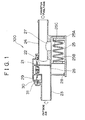
- Fig. 1 is a cross-sectional view of a flow control valve according to a first embodiment of the invention.
- Fig. 2 is a cross-sectional view of a flow control valve according to a second embodiment of the invention.
- Fig. 3 is a cross-sectional view of a flow control valve according to a third embodiment of the invention.
- Fig. 4 is an exploded perspective view of an air filter employed in a flow control valve according to the invention.
- Fig. 5 is a system diagram of a breathing mechanism of a fuel tank according to the related art.
- Fig. 6 is a cross-sectional view of a flow control valve according to the related art.
- a flow control valve 100 of this embodiment has a diaphragm-type valve body 21 and a valve port 22 that is opened and closed by the valve body 21.
- the flow control valve 100 has a communication port 23 leading to the side of outside air and a communication port 24 leading to the side of a canister (see Fig. 5).
- the valve port 22 is formed at the end of the communication port 23 leading to the side of the atmosphere. If the valve port 22 is opened, the communication port 23 comes into communication with the communication port 24.
- An air filter 25 is connected to the communication port 23 and the communication port 24 through a box member 25A.
- the box member 25A is divided into a dust-side chamber 25B and a clean-side chamber 25C by the air filter 25.
- the dust-side chamber 25B communicates with the communication port 23 through a vent hole 26.
- the clean-side chamber 25C communicates with the communication port 24 through a vent hole 27.
- a lower lid of the box member 25A may be easily removed by means of a snap-fitting joint 28 for the purpose of facilitating exchange of the air filter 25, or may be securely fixed for example by welding.
- a back pressure chamber 29 of the diaphragm-type valve body 21 communicates with the communication port 23 through a vent hole 31 formed in a case 30 of the flow control valve 100. Thereby the back pressure chamber 29 comes into communication with outside air, becomes capable of sucking and discharging air, and prevents water exposure.
- the valve body 21 opens the valve port 22. Then the fuel vapors in the fuel tank enter the communication port 23 through a canister and the communication port 24 and are discharged to the outside.
- valve body 21 opens so that the fuel vapors at a raised pressure flow to the communication port 23 through the valve port 22.
- the back pressure chamber 29 of the diaphragm-type valve body 21 sucks and discharges air as the valve body 21 moves vertically. This achieves smooth operation of the valve body 21.
- outside air is introduced into the back pressure chamber 29 through the communication port 23 and the vent hole 31. In this case, since the vent hole 31 opens to the communication port 23, water exposure is prevented.
- vent hole 31 opens to the communication port 23
- the back pressure chamber 29 is protected against dust even without a dust filter.
- Fig. 2 shows a second embodiment of the invention.
- the vent hole 31A serving as a passage for sucking air into and discharging air from the back pressure chamber 29 is formed in the case 30, and an outside air communication port 41 that extends downwards from the case 30 is connected to the vent hole 31A.
- Fig. 3 shows a third embodiment of the invention.
- a vent hole 31B serving as a passage for sucking air into and discharging air from the back pressure chamber 29 is formed in the case 30, and the vent hole 31B opens to the clean-side chamber 25C of the air filter 25.
- the air filter 25 since the air filter 25 also plays the role of a dust filter for the back pressure chamber 29, it becomes possible to cut down costs.
- Fig. 4 shows one exemplary manner in which the air filter 25 is mounted to the box member 25A in the aforementioned respective embodiments.
- a sheet of filter paper 51 folded into a zigzag (e.g. undulate, trapezoidal, saw-toothed) shape to constitute the air filter 25 is sandwiched between a male die 52 and a female die 53, which have also been formed into a zigzag shape.
- the male die 52 and the female die 53 belong to a first box member 54 and a second box member 55 respectively.
- the filter paper 51 is sandwiched between the male die 52 and the female die 53.
- the air filter is integrated with the flow control valve, no restrictions are imposed on installation space. Also, the reduced number of parts makes it possible to cut down costs and reduce the height of the flow control valve.
Landscapes
- Engineering & Computer Science (AREA)
- Chemical & Material Sciences (AREA)
- Combustion & Propulsion (AREA)
- Mechanical Engineering (AREA)
- General Engineering & Computer Science (AREA)
- Self-Closing Valves And Venting Or Aerating Valves (AREA)
- Supplying Secondary Fuel Or The Like To Fuel, Air Or Fuel-Air Mixtures (AREA)
- Details Of Valves (AREA)
- Fluid-Driven Valves (AREA)
Abstract
Description
The flow control valve also includes a second port coming into communication with the first port when the valve body is opened. A back pressure chamber of the valve body communicates with the first port through a vent hole formed in a case of the flow control valve.
Claims (6)
- A flow control valve having a diaphragm-type valve body(21), a valve port(22) opened and closed by the valve body(21), a first port (23)and a second port(24), wherein the first port(23) and the second port(24) come into communication with each other when the valve port(22) is opened, characterized in that a back pressure chamber (29)of the valve body(21) communicates with the first port (23) through a vent hole(31) formed in a case(30) of the flow control valve.
- A flow control valve having a diaphragm-type valve body(21), a valve port(22) opened and closed by the valve body(21), a first port(23) and a second port(24), wherein the first port(23) and the second port(24) come into communication with each other when the valve port(22) is opened, characterized in that a back pressure chamber(29) of the valve body communicates with outside air through a vent hole(31A) formed in a case (30)of the flow control valve.
- The flow control valve according to claim 1 or 2, characterized inthat an air filter(25) is connected to the first port(23) and the second port(24) by means of a box member(25A),that the air filter divides the box member into a first chamber(25B) and a second chamber(25C),that the first chamber(25B) communicates with the first port(23) through a vent hole(26), andthat the second chamber(25C) communicates with the second port through a vent hole(27).
- A flow control valve having a diaphragm-type valve body(21), a valve port(22) opened and closed by the valve body(21), a first port(23) and a second port(24), wherein the first port(23) and the second port(24) come into communication with each other when the valve port(22) is opened, characterized inthat an air filter(25) is mounted to the first port(23) and the second port(24) by means of a box member(25A),that the air filter(25) divides the box member(25A) into a first chamber (25B) and a second chamber(25C),that the first chamber(25B) communicates with the first port(23) through a vent hole(26),that the second chamber(25C) communicates with the second port(24) through a vent hole(27), andthat a back pressure chamber(29) of the valve body communicates with the second chamber(25C) through a vent hole(31B) formed in a case(30) of the flow control valve.
- The flow control valve according to claim 4 or 5, characterized in that the first chamber (25B) is a dust-side chamber, and the second chamber (25C) is a clean-side chamber.
- The flow control valve according to any one of claims 3 to 5, characterized inthat a sheet of filter paper(51) constituting the air filter(25) is folded into a zigzag shape, andthat the filter paper(51) is sandwiched between a male die(52) formed in a first portion(54) of the box member and a female die(53) formed in a second portion(55) of the box member, the male die(52) and the female die(53) corresponding in shape to the filter paper.
Applications Claiming Priority (2)
| Application Number | Priority Date | Filing Date | Title |
|---|---|---|---|
| JP36257899 | 1999-12-21 | ||
| JP36257899A JP2001173810A (en) | 1999-12-21 | 1999-12-21 | Flow control valve |
Publications (3)
| Publication Number | Publication Date |
|---|---|
| EP1111282A2 true EP1111282A2 (en) | 2001-06-27 |
| EP1111282A3 EP1111282A3 (en) | 2002-03-13 |
| EP1111282B1 EP1111282B1 (en) | 2004-08-25 |
Family
ID=18477215
Family Applications (1)
| Application Number | Title | Priority Date | Filing Date |
|---|---|---|---|
| EP00127827A Expired - Lifetime EP1111282B1 (en) | 1999-12-21 | 2000-12-19 | Flow control valve |
Country Status (4)
| Country | Link |
|---|---|
| US (1) | US6546954B2 (en) |
| EP (1) | EP1111282B1 (en) |
| JP (1) | JP2001173810A (en) |
| DE (1) | DE60013235T2 (en) |
Families Citing this family (15)
| Publication number | Priority date | Publication date | Assignee | Title |
|---|---|---|---|---|
| US6758835B2 (en) | 2002-05-01 | 2004-07-06 | Medtg, Llc | Disposable needle assembly having sensors formed therein permitting the simultaneous drawing and administering of fluids and method of forming the same |
| US7070641B1 (en) * | 2003-12-03 | 2006-07-04 | Fleetguard, Inc. | Carbon media filter element |
| US6918405B2 (en) * | 2003-12-04 | 2005-07-19 | Alfmeier Corporation | Fill limit vent valve |
| US7318576B2 (en) | 2004-05-27 | 2008-01-15 | Alfmeier Prazision Ag Baugruppen Und Systemlosungen | Bi-directional air valve for a tank system of a motor vehicle |
| DE102005036932B8 (en) * | 2005-08-05 | 2008-07-03 | Alfmeier Präzision AG Baugruppen und Systemlösungen | Bleed valve for the fuel tank of motor vehicles |
| JP4722870B2 (en) * | 2007-02-28 | 2011-07-13 | 愛三工業株式会社 | Dust filter for evaporative fuel processing equipment |
| EP2326861B1 (en) * | 2008-07-29 | 2013-03-13 | OPW Fluid Transfer Group Europe B.V. | Valve assembly |
| US9604837B2 (en) * | 2012-01-06 | 2017-03-28 | Husky Corporation | ORVR valve assembly |
| CA2896716C (en) | 2012-12-31 | 2020-09-15 | Medtg Llc | Infusion and blood collection device and method |
| US12478730B2 (en) | 2012-12-31 | 2025-11-25 | Medtg, Llc | Simultaneous infusion and blood collection devices |
| CN104314716A (en) | 2014-09-01 | 2015-01-28 | 重庆峰瑞塑料制品有限公司 | Novel air filter assembly with carbon tank |
| WO2021108624A1 (en) | 2019-11-26 | 2021-06-03 | Medtg, Llc | Infusion and blood collection devices and methods |
| CN112377648A (en) * | 2020-10-15 | 2021-02-19 | 北京航天石化技术装备工程有限公司 | One-way valve for low-pressure working condition |
| US11333112B2 (en) * | 2020-10-21 | 2022-05-17 | Ford Global Technologies, Llc | Method and system for a vehicle evaporative emissions control system |
| JP7417156B1 (en) | 2022-12-27 | 2024-01-18 | 詢 飯田 | valve device |
Family Cites Families (8)
| Publication number | Priority date | Publication date | Assignee | Title |
|---|---|---|---|---|
| US2638127A (en) * | 1943-09-09 | 1953-05-12 | Clayton Manufacturing Co | Molded diaphragm structure |
| US3534768A (en) * | 1968-10-11 | 1970-10-20 | Anderson Greenwood & Co | Check valve |
| US3823733A (en) * | 1970-11-02 | 1974-07-16 | Outboard Marine Corp | Diaphragm valve |
| US3746036A (en) * | 1970-11-02 | 1973-07-17 | Outboard Marine Corp | Diaphragm valve |
| US4241756A (en) * | 1978-11-29 | 1980-12-30 | C. R. Bard, Inc. | Exhalation valve assembly |
| JP3091947B2 (en) | 1994-11-30 | 2000-09-25 | 株式会社パイオラックス | Structure of negative pressure cut valve |
| US5509395A (en) | 1995-03-31 | 1996-04-23 | Siemens Electric Limited | Canister purge flow regulator |
| US5878725A (en) | 1997-10-07 | 1999-03-09 | Borg-Warner Automotive, Inc. | Canister vent/purge valve |
-
1999
- 1999-12-21 JP JP36257899A patent/JP2001173810A/en active Pending
-
2000
- 2000-12-14 US US09/735,541 patent/US6546954B2/en not_active Expired - Fee Related
- 2000-12-19 EP EP00127827A patent/EP1111282B1/en not_active Expired - Lifetime
- 2000-12-19 DE DE60013235T patent/DE60013235T2/en not_active Expired - Fee Related
Non-Patent Citations (1)
| Title |
|---|
| None |
Also Published As
| Publication number | Publication date |
|---|---|
| DE60013235D1 (en) | 2004-09-30 |
| US6546954B2 (en) | 2003-04-15 |
| EP1111282A3 (en) | 2002-03-13 |
| US20010003991A1 (en) | 2001-06-21 |
| JP2001173810A (en) | 2001-06-29 |
| EP1111282B1 (en) | 2004-08-25 |
| DE60013235T2 (en) | 2005-08-11 |
Similar Documents
| Publication | Publication Date | Title |
|---|---|---|
| EP1111282B1 (en) | Flow control valve | |
| US5335641A (en) | Oil filler for an internal combustion engine | |
| US6405747B1 (en) | Fuel tank vent valve with liquid carryover filter | |
| JP3585076B2 (en) | Fuel leak prevention valve | |
| JP4415888B2 (en) | Fuel shut-off valve | |
| US6425379B2 (en) | Evaporative emission control system | |
| US6058970A (en) | Refueling vapor recovery system with differential pressure valve | |
| US5676115A (en) | Work apparatus having an internal combustion engine | |
| US6183526B1 (en) | Filter apparatus for canister | |
| JP2003252071A (en) | Fuel supply device | |
| EP1495897B1 (en) | Fuel pump module with improved vapor vent manifold | |
| JP2002317707A (en) | Evaporative fuel control device | |
| US6361691B1 (en) | Floated fuel strainer assembly for a fuel tank | |
| JP2006029187A (en) | Fuel tank lid | |
| JP2819667B2 (en) | Vehicle fuel supply system | |
| JP2006029186A (en) | Fuel tank lid | |
| JPS6393626A (en) | Fuel tank | |
| EP1262354A1 (en) | Cover assembly for fuel tank | |
| JP4123894B2 (en) | Pump module protection structure | |
| CN112780457A (en) | Air filter for vehicle | |
| JP4898779B2 (en) | In particular, ventilation devices for fluid storage containers such as tanks | |
| CN210660370U (en) | Exhaust gas recirculation valve | |
| JPH0565753U (en) | Reservoir tank | |
| US11719235B2 (en) | Hydraulic device for a rail vehicle | |
| JP7380427B2 (en) | internal combustion engine air cleaner |
Legal Events
| Date | Code | Title | Description |
|---|---|---|---|
| PUAI | Public reference made under article 153(3) epc to a published international application that has entered the european phase |
Free format text: ORIGINAL CODE: 0009012 |
|
| AK | Designated contracting states |
Kind code of ref document: A2 Designated state(s): AT BE CH CY DE DK ES FI FR GB GR IE IT LI LU MC NL PT SE TR Kind code of ref document: A2 Designated state(s): DE FR GB IT |
|
| AX | Request for extension of the european patent |
Free format text: AL;LT;LV;MK;RO;SI |
|
| PUAL | Search report despatched |
Free format text: ORIGINAL CODE: 0009013 |
|
| AK | Designated contracting states |
Kind code of ref document: A3 Designated state(s): AT BE CH CY DE DK ES FI FR GB GR IE IT LI LU MC NL PT SE TR |
|
| AX | Request for extension of the european patent |
Free format text: AL;LT;LV;MK;RO;SI |
|
| RIC1 | Information provided on ipc code assigned before grant |
Free format text: 7F 16K 24/06 A, 7F 02M 25/08 B, 7F 16K 24/00 B |
|
| 17P | Request for examination filed |
Effective date: 20020902 |
|
| AKX | Designation fees paid |
Free format text: DE FR GB IT |
|
| GRAP | Despatch of communication of intention to grant a patent |
Free format text: ORIGINAL CODE: EPIDOSNIGR1 |
|
| GRAS | Grant fee paid |
Free format text: ORIGINAL CODE: EPIDOSNIGR3 |
|
| GRAA | (expected) grant |
Free format text: ORIGINAL CODE: 0009210 |
|
| AK | Designated contracting states |
Kind code of ref document: B1 Designated state(s): DE FR GB IT |
|
| PG25 | Lapsed in a contracting state [announced via postgrant information from national office to epo] |
Ref country code: IT Free format text: LAPSE BECAUSE OF FAILURE TO SUBMIT A TRANSLATION OF THE DESCRIPTION OR TO PAY THE FEE WITHIN THE PRESCRIBED TIME-LIMIT;WARNING: LAPSES OF ITALIAN PATENTS WITH EFFECTIVE DATE BEFORE 2007 MAY HAVE OCCURRED AT ANY TIME BEFORE 2007. THE CORRECT EFFECTIVE DATE MAY BE DIFFERENT FROM THE ONE RECORDED. Effective date: 20040825 |
|
| REG | Reference to a national code |
Ref country code: GB Ref legal event code: FG4D |
|
| REG | Reference to a national code |
Ref country code: IE Ref legal event code: FG4D |
|
| REF | Corresponds to: |
Ref document number: 60013235 Country of ref document: DE Date of ref document: 20040930 Kind code of ref document: P |
|
| ET | Fr: translation filed | ||
| PLBE | No opposition filed within time limit |
Free format text: ORIGINAL CODE: 0009261 |
|
| STAA | Information on the status of an ep patent application or granted ep patent |
Free format text: STATUS: NO OPPOSITION FILED WITHIN TIME LIMIT |
|
| 26N | No opposition filed |
Effective date: 20050526 |
|
| PGFP | Annual fee paid to national office [announced via postgrant information from national office to epo] |
Ref country code: FR Payment date: 20081216 Year of fee payment: 9 |
|
| PGFP | Annual fee paid to national office [announced via postgrant information from national office to epo] |
Ref country code: DE Payment date: 20090130 Year of fee payment: 9 |
|
| PGFP | Annual fee paid to national office [announced via postgrant information from national office to epo] |
Ref country code: GB Payment date: 20081219 Year of fee payment: 9 |
|
| GBPC | Gb: european patent ceased through non-payment of renewal fee |
Effective date: 20091219 |
|
| REG | Reference to a national code |
Ref country code: FR Ref legal event code: ST Effective date: 20100831 |
|
| PG25 | Lapsed in a contracting state [announced via postgrant information from national office to epo] |
Ref country code: FR Free format text: LAPSE BECAUSE OF NON-PAYMENT OF DUE FEES Effective date: 20091231 |
|
| PG25 | Lapsed in a contracting state [announced via postgrant information from national office to epo] |
Ref country code: DE Free format text: LAPSE BECAUSE OF NON-PAYMENT OF DUE FEES Effective date: 20100701 |
|
| PG25 | Lapsed in a contracting state [announced via postgrant information from national office to epo] |
Ref country code: GB Free format text: LAPSE BECAUSE OF NON-PAYMENT OF DUE FEES Effective date: 20091219 |