EP1110759A1 - Pneumatic radial tire - Google Patents
Pneumatic radial tire Download PDFInfo
- Publication number
- EP1110759A1 EP1110759A1 EP00907991A EP00907991A EP1110759A1 EP 1110759 A1 EP1110759 A1 EP 1110759A1 EP 00907991 A EP00907991 A EP 00907991A EP 00907991 A EP00907991 A EP 00907991A EP 1110759 A1 EP1110759 A1 EP 1110759A1
- Authority
- EP
- European Patent Office
- Prior art keywords
- tire
- sheath filaments
- cord
- core filament
- pneumatic radial
- Prior art date
- Legal status (The legal status is an assumption and is not a legal conclusion. Google has not performed a legal analysis and makes no representation as to the accuracy of the status listed.)
- Withdrawn
Links
Images



Classifications
-
- D—TEXTILES; PAPER
- D07—ROPES; CABLES OTHER THAN ELECTRIC
- D07B—ROPES OR CABLES IN GENERAL
- D07B1/00—Constructional features of ropes or cables
- D07B1/06—Ropes or cables built-up from metal wires, e.g. of section wires around a hemp core
- D07B1/0606—Reinforcing cords for rubber or plastic articles
- D07B1/0646—Reinforcing cords for rubber or plastic articles comprising longitudinally preformed wires
- D07B1/0653—Reinforcing cords for rubber or plastic articles comprising longitudinally preformed wires in the core
-
- B—PERFORMING OPERATIONS; TRANSPORTING
- B60—VEHICLES IN GENERAL
- B60C—VEHICLE TYRES; TYRE INFLATION; TYRE CHANGING; CONNECTING VALVES TO INFLATABLE ELASTIC BODIES IN GENERAL; DEVICES OR ARRANGEMENTS RELATED TO TYRES
- B60C9/00—Reinforcements or ply arrangement of pneumatic tyres
- B60C9/0007—Reinforcements made of metallic elements, e.g. cords, yarns, filaments or fibres made from metal
-
- B—PERFORMING OPERATIONS; TRANSPORTING
- B60—VEHICLES IN GENERAL
- B60C—VEHICLE TYRES; TYRE INFLATION; TYRE CHANGING; CONNECTING VALVES TO INFLATABLE ELASTIC BODIES IN GENERAL; DEVICES OR ARRANGEMENTS RELATED TO TYRES
- B60C9/00—Reinforcements or ply arrangement of pneumatic tyres
- B60C9/18—Structure or arrangement of belts or breakers, crown-reinforcing or cushioning layers
- B60C9/26—Folded plies
- B60C9/263—Folded plies further characterised by an endless zigzag configuration in at least one belt ply, i.e. no cut edge being present
-
- D—TEXTILES; PAPER
- D07—ROPES; CABLES OTHER THAN ELECTRIC
- D07B—ROPES OR CABLES IN GENERAL
- D07B2201/00—Ropes or cables
- D07B2201/20—Rope or cable components
- D07B2201/2015—Strands
- D07B2201/2016—Strands characterised by their cross-sectional shape
- D07B2201/2018—Strands characterised by their cross-sectional shape oval
-
- D—TEXTILES; PAPER
- D07—ROPES; CABLES OTHER THAN ELECTRIC
- D07B—ROPES OR CABLES IN GENERAL
- D07B2201/00—Ropes or cables
- D07B2201/20—Rope or cable components
- D07B2201/2015—Strands
- D07B2201/2023—Strands with core
-
- D—TEXTILES; PAPER
- D07—ROPES; CABLES OTHER THAN ELECTRIC
- D07B—ROPES OR CABLES IN GENERAL
- D07B2201/00—Ropes or cables
- D07B2201/20—Rope or cable components
- D07B2201/2015—Strands
- D07B2201/2024—Strands twisted
- D07B2201/2029—Open winding
-
- D—TEXTILES; PAPER
- D07—ROPES; CABLES OTHER THAN ELECTRIC
- D07B—ROPES OR CABLES IN GENERAL
- D07B2201/00—Ropes or cables
- D07B2201/20—Rope or cable components
- D07B2201/2015—Strands
- D07B2201/2024—Strands twisted
- D07B2201/2029—Open winding
- D07B2201/2031—Different twist pitch
- D07B2201/2032—Different twist pitch compared with the core
-
- D—TEXTILES; PAPER
- D07—ROPES; CABLES OTHER THAN ELECTRIC
- D07B—ROPES OR CABLES IN GENERAL
- D07B2201/00—Ropes or cables
- D07B2201/20—Rope or cable components
- D07B2201/2015—Strands
- D07B2201/2038—Strands characterised by the number of wires or filaments
- D07B2201/2039—Strands characterised by the number of wires or filaments three to eight wires or filaments respectively forming a single layer
-
- D—TEXTILES; PAPER
- D07—ROPES; CABLES OTHER THAN ELECTRIC
- D07B—ROPES OR CABLES IN GENERAL
- D07B2501/00—Application field
- D07B2501/20—Application field related to ropes or cables
- D07B2501/2046—Tyre cords
Definitions
- the present invention relates to a pneumatic radial tire which provides an improved ride comfort while maintaining the durability and which can achieve further weight saving.
- the sheath filaments are simply wound around the core filament. That is, three layers are formed as viewed in a horizontal cross section. Therefore, limitations are imposed on the method of reducing the thickness of the cords so as to provide a lower profile. Furthermore, it cannot be expected that the weight of the tire will be reduced and that the ride comfort will be improved.
- a pneumatic radial tire which has tire components made of steel cords having the following features: (a) The steel cords have a (1 + N)-filament structure formed by twisting N sheath filaments together around a core filament that has been curled spirally in the longitudinal direction of the cords; (b) Horizontal cross sections of the cords have a low profile; (c) In the horizontal cross section of each cord, a gap is formed between the adjacent sheath filaments, thus forming an open structure; (d) The core filament is wedged in between the filaments; and (e) The direction in which the core filament has been curled spirally is identical with the direction in which the sheath filaments are twisted together.
- the tire components can be further thinned as described above, the bending rigidity in a direction vertical to the plane of the tire components decreases. Hence, the ride comfort can be improved further.
- the core filament is wedged in between the sheath filaments and so the sheath filaments undergo a resistance from the core filament when a longitudinal tensile force is applied.
- This characteristic prevents deformation of the cords when a tensile force is applied longitudinally of the cords during molding or vulcanization of the tire. Hence, the shape of the cords is maintained stably. Thus, deterioration of the tire uniformity is prevented.
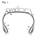
- Figs. 1-3 One example of a pneumatic radial tire in accordance with the present invention is shown in Figs. 1-3.
- the tire has a pair of beads 1 spaced from each other horizontally and a tread 4.
- Each bead 1 has a bead core 3.
- a carcass layer 2 extends into the beads 1, is outwardly bent back around each bead core 3 from inside, and is wound up.
- Four belt layers 1B, 2B, 3B, and 4B are arranged outside the carcass layer 2 in the tread 4 circumferentially of the tire and extend along the whole circumference of the tire.
- a belt cover layer 10 is disposed in addition to the tire structure shown in Fig. 1.
- the belt cover layer 10 is located outside each lateral end of belt layers 5, covers the vicinities of the lateral ends of the belt layers 5, and extends along the whole circumference of the tire.
- the belt cover layer 10 prevents the lateral ends of the belt layers 5 from being raised by centrifugal force during operation of the tire; otherwise, the cords forming the belt layers 5 would peel off from the coating rubber.
- the arrangement of the belt cover layer 10 is only required that the belt cover layer 10 cover the outside of each lateral end of the belt layers 5. To hold down at least the outside of each lateral end of the belt layers 5 by the belt cover layer 10 sufficiently, the cord angle between the belt cover layer 10 and the circumferential direction of the tire is set to almost 0°.
- a bead-reinforcing layer (finishing layer) 20 extending from inside the tire toward the outside can be placed around the carcass layer 2 and the bead cores 3 in the beads 1.
- This bead-reinforcing layer 20 is often positioned where the tire is a large-sized, heavy-duty tire used for a truck, a bus, or the like.
- a sidewall-reinforcing layer 30 is positioned from the beads to their respective sidewalls outside the carcass layer 2.
- This sidewall-reinforcing layer 30 may extend from vicinities of positions corresponding to rim flanges to vicinities of positions where the tire exhibits its maximum width.
- This sidewall-reinforcing layer 30 is mounted mainly to improve the maneuverability, and is often used in the case of a passenger-car tire.
- low-profile steel cords 40 are embedded in coating rubber 41 as shown in Fig. 4 to form a sheetlike component.
- the flattened surfaces of the steel cords 40 are made parallel to the surface of the sheetlike component.
- tire components such as the carcass layer 2, belt cover layer 10, bead-reinforcing layer 20, and the sidewall-reinforcing layer 30 as described above are formed. That is, in the horizontal cross section of Fig. 4, the major axis of each steel cord 40 is made parallel to the lateral direction of the sheetlike component.
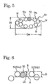
- a horizontal cross section of each steel cord 40 is shown in Fig. 5, where N sheath filaments 51 are twisted together around a core filament 50 that has been curled spirally in the longitudinal direction of the cords. Thus, a (1 + N)-filament structure is formed. Gaps are left between the adjacent ones of the filaments. That is, an open structure is formed. Furthermore, the horizontal cross-sectional shape of the cord is crushed and flattened. N is 3 to 18. In the carcass layer 2, N is 4 to 18. In the belt cover layer 10, N is 3 to 12. In the bead-reinforcing layer 20, N is 4 to 18. In the sidewall-reinforcing layer 30, N is 4 to 12.
- the N sheath filaments 51 have at least one gap between the adjacent filaments in the horizontal cross section of the cord.
- the core filament 50 is wedged into this gap and, therefore, the core filament 50 is substantially integrated with the layers of the sheath filaments 51.
- the horizontal cross section of the cord is made up of two layers. Consequently, the section height, or the minor dimension of the cross section, can be reduced further. Hence, ultra low profile steel cords can be accomplished.
- the rate at which the core filament 50 is wedged in between the adjacent filaments 51a and 51b of the sheath filaments 51 is referred to as the penetration rate and given by L 0 /D ⁇ 100% where D (corresponding to the diameter of the sheath filaments 51) is the distance between the inner common line A and the outer common line B of the filaments 51a and 51b located on opposite sides of the core filament as shown in the enlarged view of Fig. 6 showing main portions of the cords and L 0 is the distance that the core filament 50 intrudes into the interior from the inner common line A.
- the aspect ratio is given by D t /D w , where D w is the major dimension (section width) and D t is the minor dimension (section height) of the steel cord 40 in its horizontal cross section.
- the aspect ratio is 0.25 to 0.70. Where the aspect ratio is less than 0.25, excessive low profile causes the filament to be bent back excessively at both lateral ends. The filament is damaged greatly. The fatigue resistance decreases. As a result, the wires break easily. Aspect ratios in excess of 0.70 can be obtained from the prior art cord structure without relying on the present invention. However, it is difficult to mass-produce such tires on an industrial scale that they provide ride comfort and weight saving achieved by the present invention, because of high aspect ratios.
- the aspect ratio D t /D w is set to 0.25 to 0.70 in the carcass layer 2, the belt cover layer 10, and the bead-reinforcing layer 20.
- the aspect ratio D t /D w is preferably set to 0.25 to 0.60.
- the shape of the steel cords 40 of the construction described above and for use in the present invention can be stabilized against tensile force because the core filament 50 is anchored by the sheath filaments 51, even if the aspect ratio is set to 0.7 or less.
- the optimum range is preferably set according to the number N in the manner described below.
- a given length of steel cord is taken as a sample from the tire components of the tire while the coating rubber is attached.
- the sample is cut at regular intervals of 1 cm in the longitudinal direction into 50 equal parts.
- 50 cord sections are obtained.
- the range in which the cord shape-stabilizing effect is optimized is determined according to the percentage of the cord sections having penetration ratios more than a given value.
- N is 3 to 5
- 50% or more (penetration possibility) are cord sections with penetration ratios of 45% or more.
- N is 6 to 9
- 40% or more (penetration possibility) are cord sections with penetration ratios of 35% or more.
- N is 10 to 13, 30% or more (penetration possibility) are cord sections with penetration ratios of 25% or more.
- N 14 to 18, 20% or more (penetration possibility) are cord sections with penetration ratios of 20% or more. At less penetration ratios, the core filament 50 is hardly wedged in between the sheath filaments.
- N 3 to 5
- less than 50% are cord sections with such low penetration ratios.
- N 6 to 9
- less than 40% are cord sections with such low penetration ratios.
- N 10 to 13
- less than 30% are cord sections with such low penetration ratios.
- N 14 to 18, less than 20% are cord sections with such low penetration ratios. Therefore, the horizontal cross section of each steel cord substantially assumes a three-layered structure. This makes difficult to accomplish an ultra low profile.
- the direction in which the core filament 50 has been curled spirally is identical with the direction in which the sheath filaments 51 are twisted together. Where both directions are opposite, the core filament 50 and the sheath filaments 51 completely cross each other. Thus, the core filament 50 cannot be wedged in between the adjacent sheath filaments 51a and 51b.
- the spiral pitch P c of the core filament 50 is preferably set smaller than the twist pitch P s of the sheath filaments 51. More preferably, the ratio of the spiral pitch P c to the twist pitch P s , i.e., P c /P s . is set to 0.10 to 0.5. This relation can help wedge the core filament between the adjacent sheath filaments.
- the diameters of the core filament 50 and the sheath filaments 51 should be set to 0.10 to 0.30 mm. Where the diameters are less than 0.10 mm, the filaments are too thin, and the rigidity of the tire components is insufficient. Furthermore, the side wires easily move and, therefore, the code shape is unstable. On the other hand, where the diameters are in excess of 0.30 mm, the cord diameters are too large and so the tire components are thick. The bending rigidity in a direction vertical to the plane of the tire components is large. This deteriorates the ride comfort. In addition, the fatigue resistance of the wires drops. In consequence, the tire durability may deteriorate.
- the core filament 50 and the sheath filaments 51 may or may not be identical in diameter.
- the diameter of the filaments is 0.15 to 0.25 mm.
- the diameter is 0.10 to 0.25 mm.
- the diameter is 0.12 to 0.25 mm.
- the diameter is 0.15 to 0.30 mm.
- ultra-low profile open cords having an aspect ratio (D t /D w ) of 0.25 to 0.70, these cords are arranged parallel and embedded in the coating rubber.
- the obtained sheetlike component is rolled to form a tire component such as the carcass layer 2, the belt cover layer 10, the bead-reinforcing layer 20, or the sidewall-reinforcing layer 30.
- a tire component such as the carcass layer 2, the belt cover layer 10, the bead-reinforcing layer 20, or the sidewall-reinforcing layer 30.
- the ratio of the center-to-center distance d r between the two adjacent cords to the major dimension d L (equal to the section width D w ) of the cord is set to 0.25 to 0.55.
- the ratio d 1 /d 2 is set within the range described above to achieve a balance in tension between the core filament 50 and the sheath filaments 51 where a tension is applied.
- the ratio d r /d L is set within the range described above for the following reason. If this ratio d r /d L is too small (in other words, the cord spacing is too small), the separation resistance of the tire components in the carcass layer 2 or the like deteriorates. On the other hand, where this ratio is too large (in other words, the cord spacing is too large), the tire motion performance such as maneuverability drops or the cords break, deteriorating the tire durability.
- the adjacent filaments are in contact with each other at least at one location within the horizontal cross section. Not all the filaments are in contact with each other. That is, an incomplete open structure is formed. It is to be noted that the steel cords 40 used in the present invention are not limited to such an incomplete open structure. Ideally, all the filaments are isolated from each other at every location in the longitudinal direction, i.e., a complete open structure.
- the steel cords having the aforementioned characteristics are manufactured in the manner described below.
- a core filament spirally curled in the longitudinal direction is prepared. N sheath filaments are loosely twisted together around this core filament while guiding this core filament. Thus, a cord is obtained.
- This cord is then passed through plural corrective rollers and compressed by a strong pressure to flatten the cord. The applied pressure is required to be so strong that the core filament is wedged in between the sheath filaments.
- a drum durability test was carried out at a speed of 55 km/hr for 47 hours with the normal rim of JATMA (1998) under normal load.
- the amount of growth compared with the outside circumference before running was taken as an index.
- the amount of growth of Conventional Example 1 was set to 100. A lower index indicates a better result.
- Comparative Example 1 indicates a case in which the penetration possibility is too low.
- Comparative Example 2 indicates a case in which the aspect ratio is too large.
- Comparative Example 3 indicates a case in which the aspect ratio is too small.
- Comparative Example 6 indicates a case in which the core/sheath pitch ratio (P c /P s ) is too small.
- Comparative Example 7 indicates a case in which core/sheath pitch ratio (P c /P s ) is too high. Examples 1-7 are superior to Conventional Example 1 and Comparative Examples 1-7 in any one of fatigue resistance, tire outside circumference growth, and weight saving.
- Each tire under test was mounted to a rim of 16 ⁇ 7JJ at an air pressure of 200 kPa.
- the tire was run on a drum having a diameter of 1707 mm under 88% of a load corresponding to an air pressure condition stipulated by JATMA (1998) at a speed of 121 km/hr for 30 minutes. Then, the speed was increased by 8 km/hr every 30 minutes. The distance traveled until the tire failed was measured.
- the tire was evaluated with respect to this distance and represented by an index; the value of Conventional Example 2 was set to 100. A larger index gives better results.
- the air pressure inside each tire under test was set to 200 kPa.
- the tire was mounted to a passenger car of 2500-cc displacement.
- the car was run on rough road surfaces at a speed of 50 km/hr.
- the overall road noise of frequencies of 0 to 400 Hz was measured at the side of the driver's side window at the height of the driver's ear.
- the high-frequency road noise especially refers to values in the measured range around 300 Hz.
- the value obtained from the tire of Conventional Example 2 was taken as a reference value. All measured values were indicated by a relative value based on this reference value.
- the car was run on a test road surface with crisscross grooves at a speed of 50 km/hr.
- the felt ride comfort was indicated by an index; the value of Conventional Example 2 was set to 100. A greater index results in better ride comfort.
- a carcass layer was composed of steel cords used in the belt cover layer and coating rubber adhered to the steel cords.
- the weight of the carcass layer per tire was measured. The weight was indicated by an index; the value derived from Conventional Example 2 was set to 100. A smaller index gives better weight saving.
- Each tire under test was mounted to a rim of 16 ⁇ 7JJ at an air pressure of 170 kPa. The tire was allowed to stand within an ambient of 70°C ⁇ 98% RH for 30 days, thus moistening the tire. Then, the tire was run on a drum having a diameter of 1707 mm under a varying load that is 73 ⁇ 47% of a load corresponding to an air pressure condition stipulated by JATMA (1998) at a slip angle of 0 ⁇ 5° over a distance of 300 km. The load and the slip angle were varied with a rectangular wave of 0.067 Hz. After the running, the tire under test was cut and unfolded. The belt was checked if there is any wire fracture.
- Examples 8-14 are superior to Conventional Example 2 and Comparative Examples 8-16 in any one of high-speed durability, high-frequency road noise, ride comfort, weight saving, and belt durability.
- Each tire was mounted to a normal rim of JATMA (1998), and the air pressure was set to a value corresponding to the maximum load stipulated by JATMA (1998). Then, the tire was run on a drum having a diameter of 1707 mm at a speed of 45 km/hr under a maximum load condition for 2 hours. Subsequently, the tire was run under a load that is 145% of the maximum load for 12 hours. Then, the load was increased by 10% every 48 hours. The distance traveled was measured until the tire ruptured. This distance is indicated by an index; the value derived from Conventional Example 3 is set to 100. A greater index gives better results.
- the weight of the bead-reinforcing layer consisting of steel cords and coating rubber adhered to the steel cords was measured per tire. This was taken as an index; the value of Conventional Example 3 was set to 100. A smaller index indicates better weight saving.
- Example 3 indicates a case in which steel cords are used that are fabricated simply by twisting together N sheath filaments around a core filament spirally curled longitudinally of the cord to form an open, low-profile structure of (1 + N) filaments, in the same way as Conventional Example 1.
- Comparative Example 17 indicates a case in which the penetration possibility is too small.
- Comparative Example 18 indicates a case in which the aspect ratio is too large.
- Comparative Example 19 indicates a case in which the aspect ratio is too small.
- Comparative Example 22 indicates a case in which the core/sheath pitch ratio (P c /P s ) is too small.
- Comparative Example 23 indicates a case in which the core/sheath pitch ratio (P c /P s ) is too large.
- Examples 15-21 are superior to Conventional Example 3 and Comparative Examples 17-23 in any one of load durability, weight saving, and moldability.
- the cornering power (Cp) was measured under measuring conditions of an air pressure of 200 kPa, a load of 4 kN, and a slip angle of 1°.
- the maneuverability was represented by an index; the value of Conventional Example 4 was set to 100. A greater index represents a larger value of Cp, giving better maneuverability.
- the vehicle was run on a test road surface having crisscross grooves at a speed of 50 km/h.
- the felt ride comfort was indicated by an index; the value derived from Conventional Example 4 was set to 100. A smaller index provides better ride comfort.
- a sidewall-reinforcing layer was composed of steel cords and coating rubber adhered to the steel cords.
- the weight of the sidewall-reinforcing layer per tire was measured. The weight was indicated by an index; the value derived from Conventional Example 4 was set to 100. A smaller index gives better weight saving.
- Each tire under test was mounted to a rim of 16 ⁇ 7JJ at an air pressure of 180 kPa. Then, the tire was run on a drum having a diameter of 1707 mm at a speed of 81 km/hr under 85% of a maximum load corresponding to an air pressure condition specified by JATMA (1998) for 4 hours. Subsequently, the tire was run under a load that was 90% of the maximum load for 6 hours. Then, the tire was run under the maximum load for 24 hours. If there was no trouble, the tire was run under 115% of the maximum load for 4 hours. Then, the tire was run under 130% of the maximum load for 2 hours. If there was no trouble, the tire was run under 130% of the maximum load for 2 hours. Then, the tire was run under 145% of the maximum load for 4 hours. The tire was run under 160% of the maximum load. The distance traveled was measured until the tire ruptured. This distance is represented as an index; the value derived from Conventional Example 4 is set to 100.
- Conventional Example 4 indicates a case in which steel cords fabricated simply by twisting together N sheath filaments around a core filament spirally curled longitudinally of the cords to form an open, low-profile structure of (1 + N) filaments, in the same way as Conventional Example 1, are used.
- Comparative Example 24 indicates a case in which the aspect ratio is too small.
- Comparative Example 25 indicates a case in which the penetration possibility is too small.
- Comparative Example 26 indicates a case in which steel codes of 1 ⁇ 6 closed structure (where all filaments are in contact with each other) are used.
- Comparative Example 27 indicates a case in which steel codes of 1 ⁇ 6 open structure are used.
- Examples 22-24 are superior to Comparative Examples 24-27 and Conventional Example 4 in any one of maneuverability, ride comfort, weight saving, and load durability.
- the diameter d 1 of the wires forming the core filament 50 was made different from the diameter d 2 of the wires forming the sheath filaments 51.
- Steel cords having different dimensions as listed in Table 8 were used in the carcass layer as in (1) described above to fabricate pneumatic radial tires, which are referred to as Examples 25-29 and Conventional Example 1, respectively.
- This Conventional Example 1 is the same as the Conventional Example 1 in (1) above.
- the tread of each tire was polished by a given amount. Air and oxygen were sealed into the tire at a ratio of 37.5:62.5.
- the tire was mounted to a normal rim stipulated by JATMA (1998).
- a drum durability test was carried out under 140% of the maximum load at a speed of 45 km/hr to travel a given distance. The resulting amount of separation was measured. The amount of separation was indicated by an index; the value derived from Conventional Example 1 was set to 100. A smaller index provides better anti-separation of turned-up ends.
- Plural cords were aligned and coated with rubber to form rolled materials. These rolled materials were observed with an X-ray device. If the alignment of one or more cords was observed to be disturbed or a defective twist was observed, then the material was referred to as "end disturbance”. If no such phenomenon was observed, then the material was referred to as cords having "no end disturbance”. ⁇ indicates cords having unstable ends which may or may not have disturbance.
- Examples 25-29 are superior to Conventional Example 1 in any one of fatigue resistance, tire outside circumference growth, weight saving, cord shape stability, anti-separation of the turned up ends, and presence or absence of end disturbance during rolling.
- the ratio d 1 /d 2 (1.11) of Example 27 is outside the range of 1.04 to 1.08.
- Example 27 is inferior to Examples 26 and 27 in fatigue resistance (holding %) and anti-separation of the turned up ends.
- the ratio d r /d L (0.2) of Example 28 is outside the range of 0.25 to 0.55.
- Example 28 is inferior to Examples 26 and 27 in anti-separation of the turned up ends.
- the ratio d r /d L (0.6) of Example 29 is outside the range of 0.25 to 0.55.
- Example 29 is inferior to Examples 26 and 27 in fatigue resistance (holding %) and tire outside circumference growth.
- Examples 30-35 are superior to Conventional Example 2 in any one of high-speed durability, high-frequency road noise, ride comfort, weight saving, and cord shape stability (resistance of wires to fracture).
- the ratio d 1 /d 2 (1.17) of Example 33 is outside the range of 1.04 to 1.1.
- Example 33 is inferior to Examples 30-32 in high-speed durability and cord shape stability.
- the ratio d r /d L (0.2) of Example 34 is outside the range of 0.25 to 0.55.
- Example 34 is inferior to Examples 30-32 in high-speed durability.
- the ratio d r /d L (0.6) of Example 35 is outside the range of 0.25 to 0.55.
- Example 35 is inferior to Examples 30-32 in high-speed durability.
- the diameter d 1 of the wires forming the core filament 50 was made different from the diameter d 2 of the wires forming the sheath filaments 51.
- Steel cords having different dimensions as listed in Table 10 were used in the bead-reinforcing layer as in (3) described above to fabricate pneumatic radial tires, which are referred to as Examples 36-41 and Conventional Example 3, respectively.
- This Conventional Example 3 is the same as the Conventional Example 3 in (3) above.
- Examples 36-41 are superior to Conventional Example 3 in any one of load durability, weight saving, moldability, cord shape stability, and presence or absence of disturbance of ends during rolling.
- the ratio d 1 /d 2 (1.15) of Example 39 is outside the range of 1.04 to 1.1.
- Example 39 is inferior to Examples 36-38 in load durability and cord shape stability.
- the ratio d r /d L (0.2) of Example 40 is outside the range of 0.25 to 0.55.
- Example 40 is inferior to Examples 36-38 in load durability.
- the ratio d r /d L (0.6) of Example 41 is outside the range of 0.25 to 0.55.
- Example 41 is inferior to Examples 36-38 in load durability.
- the diameter d 1 of the wires forming the core filament 50 was made different from the diameter d 2 of the wires forming the sheath filaments 51.
- Steel cords having different dimensions as listed in Table 11 were used in the sidewall-reinforcing layer as in (4) described above to fabricate pneumatic radial tires, which are referred to as Examples 42-47 and Conventional Example 4, respectively.
- This Conventional Example 4 is the same as the Conventional Example 4 in (4) described above.
- Examples 42-47 are superior to Conventional Example 4 in any one of maneuverability, ride comfort, weight saving, load durability, cord shape stability, and presence or absence of disturbance of ends during rolling.
- the ratio d 1 /d 2 (1.14) of Example 45 is outside the range of 1.04 to 1.1.
- Example 45 is inferior to Examples 42-44 in maneuverability, load durability, and cord shape stability.
- the ratio d r /d L (0.2) of Example 46 is outside the range of 0.25 to 0.55.
- Example 46 is inferior to Examples 42-44 in weight saving and load durability.
- the ratio d r /d L (0.6) of Example 47 is outside the range of 0.25 to 0.55.
- Example 47 is inferior to Examples 42-44 in maneuverability and load durability.
- the penetration possibility given in Tables 1-11 is defined in the manner described below.
- a cord of the (1 + 11)-filament structure a given length of steel cord is cut into 50 equal segments of 1 cm in the longitudinal direction.
- the possibility of the presence of cord sections having penetration percent of 25% or more is the penetration possibility.
- a cord of (1 + 5)-filament structure a given length of steel cord is cut into 50 equal segments of 1 cm in the longitudinal direction.
- the possibility of the presence of cord sections having penetration percent of 45% or more is the penetration possibility.
- a cord of a (1 + 8)-filament structure a given length of steel cord is cut into 50 equal segments of 1 cm in the longitudinal direction.
- the possibility of the presence of cord sections having penetration percent of 35% or more is the penetration possibility.
- the present invention provides a pneumatic radial tire having tire components consisting of steel cords, the steel cords having the following features: (a) They have a (1 + N)-filament structure fabricated by twisting together N sheath filaments around a core filament that has been spirally curled longitudinally of the cords; (b) The horizontal cross section of each cord has a low profile; (c) In the horizontal cross section, gaps are left between the adjacent sheath filaments, thus forming an open structure; (d) The core filament is wedged in between the sheath filaments; and (e) The direction in which the core filament has been spirally curled is identical with the direction in which the sheath filaments are twisted together.
- an ultra low profile can be imparted to the steel cords used in the tire components such as carcass layer, belt cover layer, bead-reinforcing layer, and sidewall-reinforcing layer. This can produce a more comfortable ride. Furthermore, the weight can be reduced further.
Landscapes
- Engineering & Computer Science (AREA)
- Mechanical Engineering (AREA)
- Tires In General (AREA)
- Ropes Or Cables (AREA)
Abstract
A pneumatic radial tire having tire components
consisting of steel cords. These steel cords have the
following features: (a) The cords have a (1 + N)-filament
structure fabricated by twisting together N
sheath filaments around a core filament that has been
spirally curled longitudinally of the cords; (b) The
horizontal cross section of each cord has a low
profile; (c) In the horizontal cross section of the
cord, gaps are left between the adjacent sheath
filaments, thus forming an open structure; (d) The
core filament is wedged in between the sheath
filaments; and (e) The direction in which the sheath
filaments are twisted together is identical with the
direction in which the core filament has been spirally
curled.
Description
The present invention relates to a pneumatic
radial tire which provides an improved ride comfort
while maintaining the durability and which can achieve
further weight saving.
In recent years, stricter weight saving
requirements have been imposed on tires. Where a tire
component forming a tire such as a carcass layer is
fabricated by embedding steel cords in coating rubber
made of a rubber compound, weight reduction can be
accomplished by reducing the amount of the used steel
cords or coating rubber. However, reducing the amount
of the used steel cords makes the rigidity of the tire
insufficient. Also, the tire performance, especially
the durability, deteriorates greatly.
Accordingly, various contrivances have been made
to reduce the amount of the used coating rubber. For
example, in the technique described in Japanese patent
application Kokai publication No. 8-325962, a core
filament formed by curling steel cords spirally in the
longitudinal direction of the cords is used. N sheath
filaments are twisted together around the core filament
to form a flattened open structure of (1 + N)
filaments. Where steel cords are embedded in the
coating rubber, the thickness of the rubber gauge is
reduced. As a result, the amount of the used rubber is
decreased. Also, the rubber is made to penetrate deeper
into the steel cords, thus preventing rusting of the
steel cords which would otherwise be caused by
intrusion of water.
In the steel cords of the flattened open
structure of the (1 + N) filaments described above,
the sheath filaments are simply wound around the core
filament. That is, three layers are formed as viewed
in a horizontal cross section. Therefore, limitations
are imposed on the method of reducing the thickness of
the cords so as to provide a lower profile.
Furthermore, it cannot be expected that the weight of
the tire will be reduced and that the ride comfort
will be improved.
It is an object of the present invention to
provide a pneumatic radial tire in which steel cords
used in tire components such as a carcass layer, a
belt cover layer, a bead-reinforcing layer, and a
sidewall-reinforcing layer are made to have an ultra
low profile, thus improving the ride comfort and
accomplishing further weight saving.
This object is achieved in accordance with the
teachings of the invention by a pneumatic radial tire
which has tire components made of steel cords having
the following features: (a) The steel cords have a (1
+ N)-filament structure formed by twisting N sheath
filaments together around a core filament that has
been curled spirally in the longitudinal direction of
the cords; (b) Horizontal cross sections of the cords
have a low profile; (c) In the horizontal cross
section of each cord, a gap is formed between the
adjacent sheath filaments, thus forming an open
structure; (d) The core filament is wedged in between
the filaments; and (e) The direction in which the core
filament has been curled spirally is identical with
the direction in which the sheath filaments are
twisted together.
Since the steel cords are so designed that the
core filament is wedged in between the adjacent sheath
filaments in this way, two horizontal steel-code layers
are formed. The vertical dimension, or height, can be
more easily reduced than the three-layered structure in
which sheath filaments simply surround a core filament.
Consequently, ultra low-profile steel cords with an
aspect ratio (profile ratio) of 0.7 or less which have
been regarded as impossible to mass-produce on an
industrial scale can be accomplished. Accordingly, by
embedding the flattened surfaces of the steel cords in
coating rubber to form tire components, reductions in
their thickness can be achieved. This can contribute to
a further reduction in the tire weight.
Because the tire components can be further
thinned as described above, the bending rigidity in a
direction vertical to the plane of the tire components
decreases. Hence, the ride comfort can be improved
further.
Furthermore, the core filament is wedged in
between the sheath filaments and so the sheath
filaments undergo a resistance from the core filament
when a longitudinal tensile force is applied. This
stabilizes the twisted form of the sheath filaments in
the longitudinal direction. This characteristic
prevents deformation of the cords when a tensile force
is applied longitudinally of the cords during molding
or vulcanization of the tire. Hence, the shape of the
cords is maintained stably. Thus, deterioration of the
tire uniformity is prevented.
One example of a pneumatic radial tire in
accordance with the present invention is shown in
Figs. 1-3. In Fig. 1, the tire has a pair of beads 1
spaced from each other horizontally and a tread 4.
Each bead 1 has a bead core 3. A carcass layer 2
extends into the beads 1, is outwardly bent back around
each bead core 3 from inside, and is wound up. Four
belt layers 1B, 2B, 3B, and 4B are arranged outside the
carcass layer 2 in the tread 4 circumferentially of the
tire and extend along the whole circumference of the
tire.
In Fig. 2, a belt cover layer 10 is disposed in
addition to the tire structure shown in Fig. 1. The
belt cover layer 10 is located outside each lateral
end of belt layers 5, covers the vicinities of the
lateral ends of the belt layers 5, and extends along
the whole circumference of the tire. The belt cover
layer 10 prevents the lateral ends of the belt layers
5 from being raised by centrifugal force during
operation of the tire; otherwise, the cords forming
the belt layers 5 would peel off from the coating
rubber. The arrangement of the belt cover layer 10 is
only required that the belt cover layer 10 cover the
outside of each lateral end of the belt layers 5. To
hold down at least the outside of each lateral end of
the belt layers 5 by the belt cover layer 10
sufficiently, the cord angle between the belt cover
layer 10 and the circumferential direction of the tire
is set to almost 0°.
In Fig. 1, a bead-reinforcing layer (finishing
layer) 20 extending from inside the tire toward the
outside can be placed around the carcass layer 2 and
the bead cores 3 in the beads 1. This bead-reinforcing
layer 20 is often positioned where the tire is a
large-sized, heavy-duty tire used for a truck, a bus,
or the like.
In Fig. 3, a sidewall-reinforcing layer 30 is
positioned from the beads to their respective sidewalls
outside the carcass layer 2. This sidewall-reinforcing
layer 30 may extend from vicinities of positions
corresponding to rim flanges to vicinities of positions
where the tire exhibits its maximum width. This
sidewall-reinforcing layer 30 is mounted mainly to
improve the maneuverability, and is often used in the
case of a passenger-car tire.
In the present invention, low-profile steel cords
40 are embedded in coating rubber 41 as shown in Fig. 4
to form a sheetlike component. The flattened surfaces
of the steel cords 40 are made parallel to the surface
of the sheetlike component. Thus, tire components such
as the carcass layer 2, belt cover layer 10, bead-reinforcing
layer 20, and the sidewall-reinforcing
layer 30 as described above are formed. That is, in the
horizontal cross section of Fig. 4, the major axis of
each steel cord 40 is made parallel to the lateral
direction of the sheetlike component.
A horizontal cross section of each steel cord 40
is shown in Fig. 5, where N sheath filaments 51 are
twisted together around a core filament 50 that has
been curled spirally in the longitudinal direction of
the cords. Thus, a (1 + N)-filament structure is
formed. Gaps are left between the adjacent ones of the
filaments. That is, an open structure is formed.
Furthermore, the horizontal cross-sectional shape of
the cord is crushed and flattened. N is 3 to 18. In
the carcass layer 2, N is 4 to 18. In the belt cover
layer 10, N is 3 to 12. In the bead-reinforcing layer
20, N is 4 to 18. In the sidewall-reinforcing layer
30, N is 4 to 12. The N sheath filaments 51 have at
least one gap between the adjacent filaments in the
horizontal cross section of the cord. The core
filament 50 is wedged into this gap and, therefore,
the core filament 50 is substantially integrated with
the layers of the sheath filaments 51. In this way,
the horizontal cross section of the cord is made up of
two layers. Consequently, the section height, or the
minor dimension of the cross section, can be reduced
further. Hence, ultra low profile steel cords can be
accomplished.
The rate at which the core filament 50 is wedged
in between the adjacent filaments 51a and 51b of the
sheath filaments 51 is referred to as the penetration
rate and given by
L0 /D × 100%
where D (corresponding to the diameter of the sheath
filaments 51) is the distance between the inner common
line A and the outer common line B of the filaments 51a
and 51b located on opposite sides of the core filament
as shown in the enlarged view of Fig. 6 showing main
portions of the cords and L0 is the distance that the
core filament 50 intrudes into the interior from the
inner common line A.
The aspect ratio (profile ratio) is given by
Dt/Dw, where Dw is the major dimension (section width)
and Dt is the minor dimension (section height) of the
steel cord 40 in its horizontal cross section. The
aspect ratio is 0.25 to 0.70. Where the aspect ratio is
less than 0.25, excessive low profile causes the
filament to be bent back excessively at both lateral
ends. The filament is damaged greatly. The fatigue
resistance decreases. As a result, the wires break
easily. Aspect ratios in excess of 0.70 can be obtained
from the prior art cord structure without relying on
the present invention. However, it is difficult to
mass-produce such tires on an industrial scale that
they provide ride comfort and weight saving achieved by
the present invention, because of high aspect ratios.
The aspect ratio Dt/Dw is set to 0.25 to 0.70 in the
carcass layer 2, the belt cover layer 10, and the bead-reinforcing
layer 20. In the sidewall-reinforcing layer
30, the aspect ratio Dt/Dw is preferably set to 0.25 to
0.60.
The shape of the steel cords 40 of the
construction described above and for use in the present
invention can be stabilized against tensile force
because the core filament 50 is anchored by the sheath
filaments 51, even if the aspect ratio is set to 0.7 or
less. With respect to this cord shape-stabilizing
effect, as the number of sheath filaments of the (1 +
N)-filament structure is reduced, the core filament 50
tends to be wedged in deeper between the sheath
filaments, and vice versa. Therefore, the optimum range
is preferably set according to the number N in the
manner described below.
A given length of steel cord is taken as a
sample from the tire components of the tire while the
coating rubber is attached. The sample is cut at
regular intervals of 1 cm in the longitudinal
direction into 50 equal parts. Thus, 50 cord sections
are obtained. The range in which the cord shape-stabilizing
effect is optimized is determined
according to the percentage of the cord sections
having penetration ratios more than a given value.
Where N is 3 to 5, 50% or more (penetration
possibility) are cord sections with penetration ratios
of 45% or more. Where N is 6 to 9, 40% or more
(penetration possibility) are cord sections with
penetration ratios of 35% or more. Where N is 10 to
13, 30% or more (penetration possibility) are cord
sections with penetration ratios of 25% or more. Where
N is 14 to 18, 20% or more (penetration possibility)
are cord sections with penetration ratios of 20% or
more. At less penetration ratios, the core filament 50
is hardly wedged in between the sheath filaments. In
particular, where N is 3 to 5, less than 50% are cord
sections with such low penetration ratios. Where N is
6 to 9, less than 40% are cord sections with such low
penetration ratios. Where N is 10 to 13, less than 30%
are cord sections with such low penetration ratios.
Where N is 14 to 18, less than 20% are cord sections
with such low penetration ratios. Therefore, the
horizontal cross section of each steel cord
substantially assumes a three-layered structure. This
makes difficult to accomplish an ultra low profile.
These penetration ratio and penetration possibility
can be checked by taking steel cords from the
vulcanized tire while the coating rubber is attached,
cutting the cords, and examining them.
In the steel code filaments used in the present
invention, the direction in which the core filament 50
has been curled spirally is identical with the
direction in which the sheath filaments 51 are twisted
together. Where both directions are opposite, the core
filament 50 and the sheath filaments 51 completely
cross each other. Thus, the core filament 50 cannot be
wedged in between the adjacent sheath filaments 51a
and 51b.
As shown in Fig. 7, the spiral pitch Pc of the
core filament 50 is preferably set smaller than the
twist pitch Ps of the sheath filaments 51. More
preferably, the ratio of the spiral pitch Pc to the
twist pitch Ps, i.e., Pc/Ps. is set to 0.10 to 0.5. This
relation can help wedge the core filament between the
adjacent sheath filaments.
The diameters of the core filament 50 and the
sheath filaments 51 should be set to 0.10 to 0.30 mm.
Where the diameters are less than 0.10 mm, the
filaments are too thin, and the rigidity of the tire
components is insufficient. Furthermore, the side wires
easily move and, therefore, the code shape is unstable.
On the other hand, where the diameters are in excess of
0.30 mm, the cord diameters are too large and so the
tire components are thick. The bending rigidity in a
direction vertical to the plane of the tire components
is large. This deteriorates the ride comfort. In
addition, the fatigue resistance of the wires drops. In
consequence, the tire durability may deteriorate. The
core filament 50 and the sheath filaments 51 may or may
not be identical in diameter. In the carcass layer 2,
the diameter of the filaments is 0.15 to 0.25 mm. In
the belt cover layer 10, the diameter is 0.10 to 0.25
mm. In the bead-reinforcing layer 20, the diameter is
0.12 to 0.25 mm. In the sidewall-reinforcing layer 30,
the diameter is 0.15 to 0.30 mm.
In the (1 + N)-filament, ultra-low profile open
cords having an aspect ratio (Dt/Dw) of 0.25 to 0.70,
these cords are arranged parallel and embedded in the
coating rubber. The obtained sheetlike component is
rolled to form a tire component such as the carcass
layer 2, the belt cover layer 10, the bead-reinforcing
layer 20, or the sidewall-reinforcing layer 30. In this
case, there is a danger of great deterioration of the
tire durability. That is, when the sheetlike component
obtained by embedding the cords in the coating rubber
is rolled, the ends of the cord arrangement are
disturbed. This leads to a deterioration of the tire
durability. To avoid this problem, the ratio d1/d2
(where d1 is the diameter of the wires of the core
filament 50 and d2 is the diameter of the wires of the
sheath filaments 51) is preferably set to 1.04 to 1.1
provided that N = 3 to 8. The ratio d1/d2 is set to
1.04 to 1.08 provided that N = 9 to 18. Preferably, the
ratio of the center-to-center distance dr between the
two adjacent cords to the major dimension dL (equal to
the section width Dw) of the cord is set to 0.25 to
0.55.
The ratio d1/d2 is set within the range described
above to achieve a balance in tension between the core
filament 50 and the sheath filaments 51 where a tension
is applied. The ratio dr/dL is set within the range
described above for the following reason. If this ratio
dr/dL is too small (in other words, the cord spacing is
too small), the separation resistance of the tire
components in the carcass layer 2 or the like
deteriorates. On the other hand, where this ratio is
too large (in other words, the cord spacing is too
large), the tire motion performance such as
maneuverability drops or the cords break, deteriorating
the tire durability.
In the open structure of the steel cord 40 shown
in Fig. 5, the adjacent filaments are in contact with
each other at least at one location within the
horizontal cross section. Not all the filaments are in
contact with each other. That is, an incomplete open
structure is formed. It is to be noted that the steel
cords 40 used in the present invention are not limited
to such an incomplete open structure. Ideally, all the
filaments are isolated from each other at every
location in the longitudinal direction, i.e., a
complete open structure.
The steel cords having the aforementioned
characteristics are manufactured in the manner
described below. First, a core filament spirally curled
in the longitudinal direction is prepared. N sheath
filaments are loosely twisted together around this core
filament while guiding this core filament. Thus, a cord
is obtained. This cord is then passed through plural
corrective rollers and compressed by a strong pressure
to flatten the cord. The applied pressure is required
to be so strong that the core filament is wedged in
between the sheath filaments.
(1) Several samples of the tire structure
similar to the structure shown in Fig. 1 except that
the bead-reinforcing layer 20 was not present were
formed. The tire sizes of all the samples were
11R22.5. The samples had steel cords having different
dimensions as listed in Tables 1 and 2. These steel
cords were used in the carcass layer of each sample.
In this way, pneumatic radial tires were fabricated as
Examples 1-7, Conventional Example 1, and Comparative
Examples 1-7, respectively. Conventional Example 1 is
a tire using the cords described in the above-cited
Japanese patent application Kokai publication No. 8-325962.
That is, the steel cords used in Conventional
Example 1 are of an open structure having (1 + N)
filaments and a low profile fabricated by twisting
together N sheath filaments around a core filament
spirally curled longitudinally of the cords.
The fatigue resistance, the tire outside
circumference growth, weight saving, and shape
stability of cords of these samples of tires were
measured by the following measuring methods and
evaluated. The results are given in Tables 1 and 2.
Each tire was run over a distance of 100 thousand
kilometers. Wires were taken from the tire. The wires
were subjected to a fatigue test by a rotation bending
fatigue testing machine. The wires were evaluated with
respect to the rotational frequency at which a rupture
occurred. Holding Percent (%) = (rotational frequency
at which the wire ruptured after the tire was run and
the wire was taken from the tire)/(rotational frequency
at which the wire ruptured after the wire was taken
from an unrun tire) x 100. Every index is set under
condition that the holding percent of Conventional
Example 1 is set to 100. A greater index indicates
better fatigue resistance.
A drum durability test was carried out at a
speed of 55 km/hr for 47 hours with the normal rim of
JATMA (1998) under normal load. The amount of growth
compared with the outside circumference before running
was taken as an index. The amount of growth of
Conventional Example 1 was set to 100. A lower index
indicates a better result.
The weight of the carcass layer consisting of
steel cords and coating rubber adhered to the steel
cords was measured per tire. This was taken as an
index; the value of Conventional Example was set to
100. A smaller index indicates better weight saving.
Cord Shape Stability
Defective twists in steel cords per meter were
measured with a stereoscopic microscope. Samples were
taken at random. Five measurements (N = 5) were made,
and their average was calculated. The result is taken
as an index; the value of Conventional Example 1 is
set to 100. A smaller index indicates better cord
shape stability.


In Tables 1 and 2, Comparative Example 1
indicates a case in which the penetration possibility
is too low. Comparative Example 2 indicates a case in
which the aspect ratio is too large. Comparative
Example 3 indicates a case in which the aspect ratio
is too small. Comparative Example 6 indicates a case
in which the core/sheath pitch ratio (Pc/Ps) is too
small. Comparative Example 7 indicates a case in which
core/sheath pitch ratio (Pc/Ps) is too high. Examples
1-7 are superior to Conventional Example 1 and
Comparative Examples 1-7 in any one of fatigue
resistance, tire outside circumference growth, and
weight saving.
(2) Samples of pneumatic radial tire of the
construction shown in Fig. 2 were fabricated. Their
tire sizes were all 205/55 R16. However, they used
steel cords having different dimensions as listed in
Tables 3 and 4, the steel cords being inserted in belt
cover layers. These samples are referred to as
Examples 8-14, Conventional Example 2, and Comparative
Examples 8-16, respectively.
Various characteristics (i.e., high-speed
durability, high-frequency road noise, ride comfort,
belt durability (the resistance of the wires to
breaking), and cord shape stability) of these tires
were evaluated by the following measuring methods. The
results are given in Tables 3 and 4.
Each tire under test was mounted to a rim of 16
× 7JJ at an air pressure of 200 kPa. The tire was run
on a drum having a diameter of 1707 mm under 88% of a
load corresponding to an air pressure condition
stipulated by JATMA (1998) at a speed of 121 km/hr for
30 minutes. Then, the speed was increased by 8 km/hr
every 30 minutes. The distance traveled until the tire
failed was measured. The tire was evaluated with
respect to this distance and represented by an index;
the value of Conventional Example 2 was set to 100. A
larger index gives better results.
The air pressure inside each tire under test was
set to 200 kPa. The tire was mounted to a passenger car
of 2500-cc displacement. The car was run on rough road
surfaces at a speed of 50 km/hr. The overall road noise
of frequencies of 0 to 400 Hz was measured at the side
of the driver's side window at the height of the
driver's ear. The high-frequency road noise especially
refers to values in the measured range around 300 Hz.
The value obtained from the tire of Conventional
Example 2 was taken as a reference value. All measured
values were indicated by a relative value based on this
reference value.
The car was run on a test road surface with
crisscross grooves at a speed of 50 km/hr. The felt
ride comfort was indicated by an index; the value of
Conventional Example 2 was set to 100. A greater index
results in better ride comfort.
A carcass layer was composed of steel cords used
in the belt cover layer and coating rubber adhered to
the steel cords. The weight of the carcass layer per
tire was measured. The weight was indicated by an
index; the value derived from Conventional Example 2
was set to 100. A smaller index gives better weight
saving.
Each tire under test was mounted to a rim of 16
× 7JJ at an air pressure of 170 kPa. The tire was
allowed to stand within an ambient of 70°C × 98% RH for
30 days, thus moistening the tire. Then, the tire was
run on a drum having a diameter of 1707 mm under a
varying load that is 73 ± 47% of a load corresponding
to an air pressure condition stipulated by JATMA (1998)
at a slip angle of 0 ± 5° over a distance of 300 km.
The load and the slip angle were varied with a
rectangular wave of 0.067 Hz. After the running, the
tire under test was cut and unfolded. The belt was
checked if there is any wire fracture.
Defective twists in steel cords per meter were
measured with a stereoscopic microscope. Samples were
taken at random. Five measurements (N = 5) were made,
and their average was calculated. The result is taken
as an index; the value of Comparative Example 9 is set
to 100. A smaller index indicates better cord shape
stability.

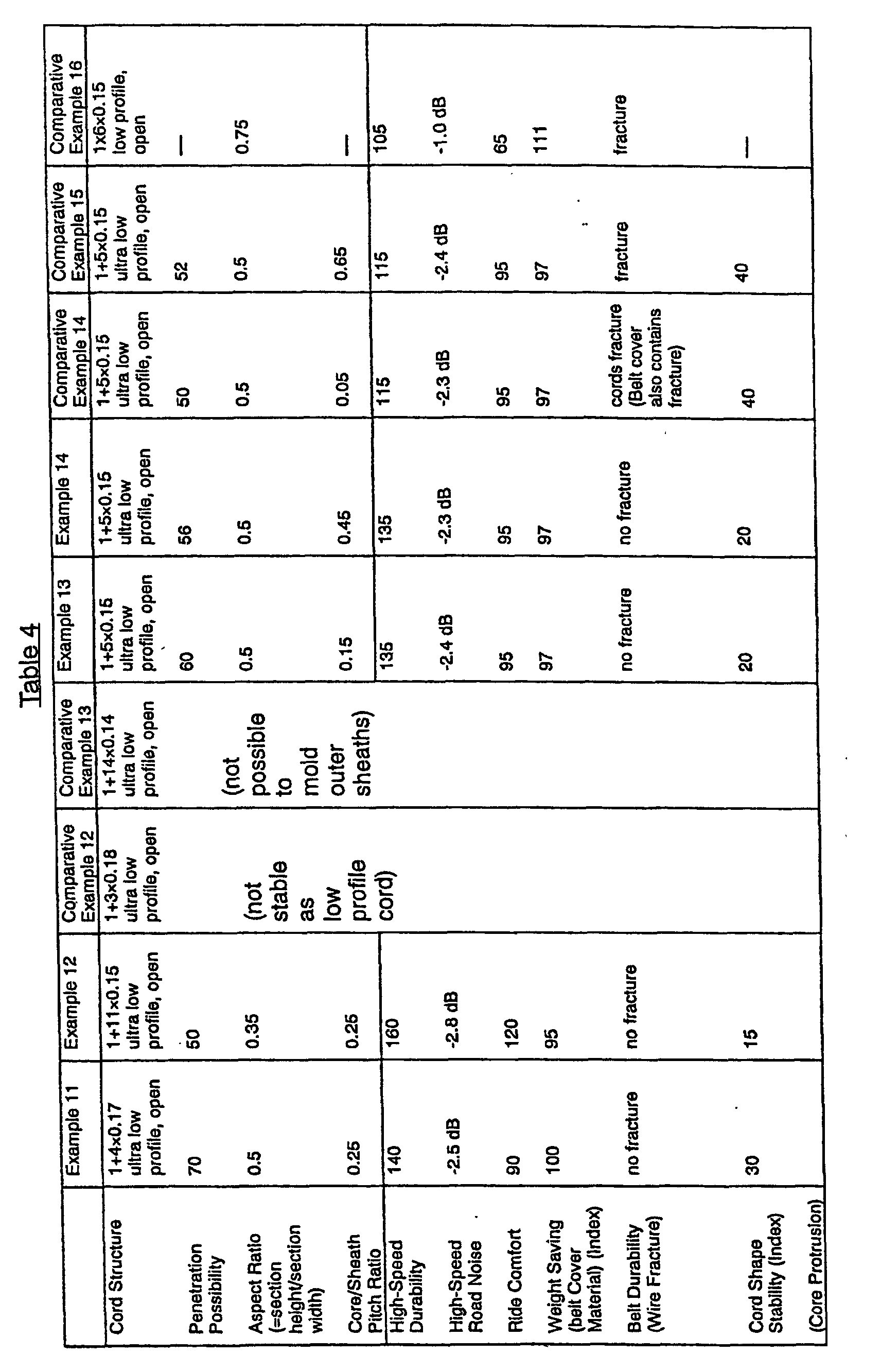
In Tables 3 and 4, Conventional Example 2
indicates a case in which two-stranded 66-nylon cord
(66N1260d/2) of 1260 denier is used in the belt cover
layer. Comparative Example 8 indicates a case in which
the penetration possibility is too low. Comparative
Example 9 indicates a case in which the penetration
possibility is zero. Comparative Example 10 indicates
a case in which the aspect ratio is too large.
Comparative Example 11 indicates a case in which the
aspect ratio is too small. Comparative Example 14
indicates a case in which the core/sheath pitch ratio
(Pc/Ps) is too small. Comparative Example 15 indicates
a case in which the core/sheath pitch ratio (Pc/Ps) is
too large. Comparative Example 16 indicates a case in
which the prior art open, low-profile structure is
used.
Examples 8-14 are superior to Conventional
Example 2 and Comparative Examples 8-16 in any one of
high-speed durability, high-frequency road noise, ride
comfort, weight saving, and belt durability.
(3) Samples of pneumatic radial tire of the
construction shown in Fig. 1 were fabricated. Their
tire sizes were all 11R22.5. However, they used steel
cords having different dimensions as listed in Tables
5 and 6, the steel cords being inserted in bead-reinforcing
layers. These samples are referred to as
Examples 15-21, Conventional Example 3, and
Comparative Examples 17-23, respectively.
The load durability, weight saving, moldability,
and cord shape stability of each of these tires were
evaluated by the measuring methods described below.
The results are given in Tables 5 and 6.
Each tire was mounted to a normal rim of JATMA
(1998), and the air pressure was set to a value
corresponding to the maximum load stipulated by JATMA
(1998). Then, the tire was run on a drum having a
diameter of 1707 mm at a speed of 45 km/hr under a
maximum load condition for 2 hours. Subsequently, the
tire was run under a load that is 145% of the maximum
load for 12 hours. Then, the load was increased by 10%
every 48 hours. The distance traveled was measured
until the tire ruptured. This distance is indicated by
an index; the value derived from Conventional Example
3 is set to 100. A greater index gives better results.
The weight of the bead-reinforcing layer
consisting of steel cords and coating rubber adhered
to the steel cords was measured per tire. This was
taken as an index; the value of Conventional Example 3
was set to 100. A smaller index indicates better
weight saving.
The ease with which the steel cords are turned
up in the bead portions was evaluated with respect to
failure in the bead portions. This operation for
turning up the steel cords is necessary during molding
of tires. The value obtained from Conventional Example
3 is taken as a reference. o ○ indicates a very good
state. O indicates a relatively good state. x indicates
a defective state.
Defective twists in steel cords per meter were
measured with a stereoscopic microscope. Samples were
taken at random. Five measurements (N = 5) were made,
and their average was calculated. The result is taken
as an index; the value of Conventional Example 3 was
set to 100. A smaller index gives better cord shape
stability.

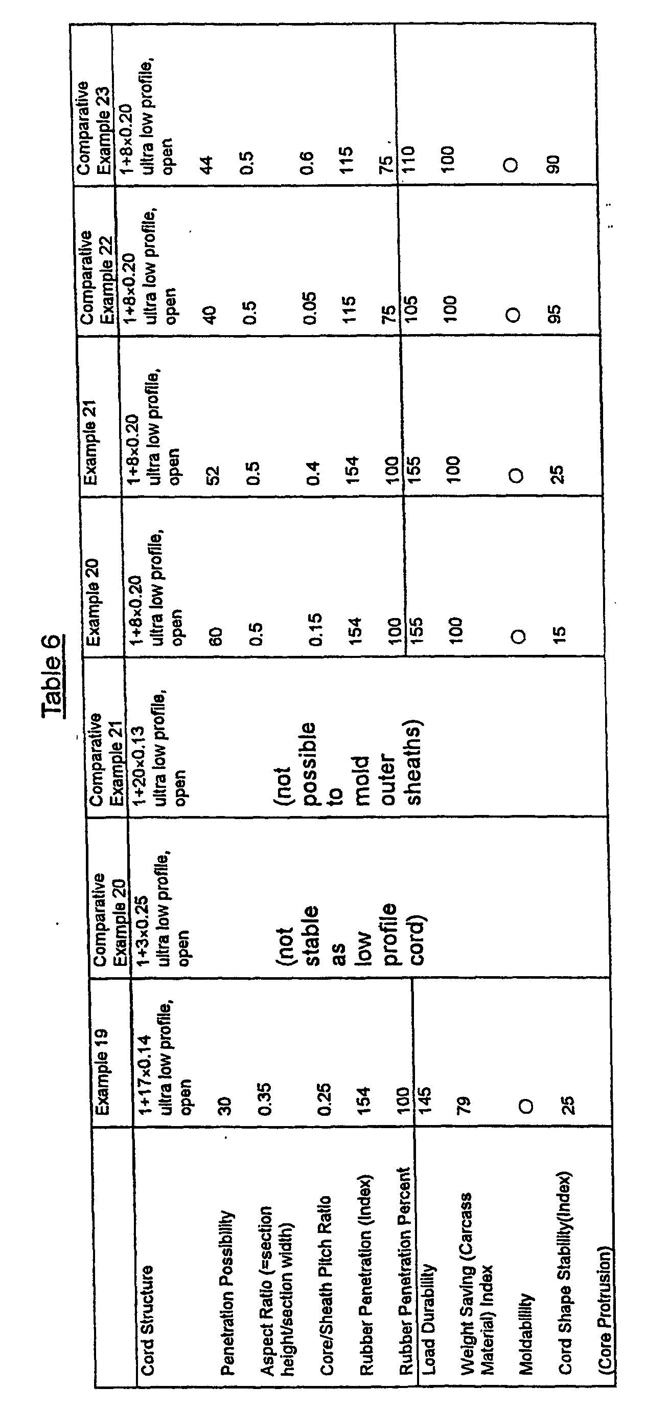
In Tables 5 and 6, Conventional Example 3
indicates a case in which steel cords are used that
are fabricated simply by twisting together N sheath
filaments around a core filament spirally curled
longitudinally of the cord to form an open, low-profile
structure of (1 + N) filaments, in the same
way as Conventional Example 1. Comparative Example 17
indicates a case in which the penetration possibility
is too small. Comparative Example 18 indicates a case
in which the aspect ratio is too large. Comparative
Example 19 indicates a case in which the aspect ratio
is too small. Comparative Example 22 indicates a case
in which the core/sheath pitch ratio (Pc/Ps) is too
small. Comparative Example 23 indicates a case in
which the core/sheath pitch ratio (Pc/Ps) is too large.
Examples 15-21 are superior to Conventional Example 3
and Comparative Examples 17-23 in any one of load
durability, weight saving, and moldability.
(4) Samples of pneumatic radial tire of the
construction shown in Fig. 3 were fabricated. Their
tire sizes were all 205/55 R16. However, they used
steel cords having different dimensions as listed in
Table 7, the steel cords being used in the sidewall-reinforcing
layers. These samples are referred to as
Examples 22-24, Comparative Examples 24-27, and
Conventional Example 4, respectively.
These tires were evaluated with respect to
maneuverability, ride comfort, weight saving, load
durability, and cord shape stability by the following
measuring methods. The results are given in Table 7.
The cornering power (Cp) was measured under
measuring conditions of an air pressure of 200 kPa, a
load of 4 kN, and a slip angle of 1°.
The maneuverability was represented by an index;
the value of Conventional Example 4 was set to 100. A
greater index represents a larger value of Cp, giving
better maneuverability.
The vehicle was run on a test road surface
having crisscross grooves at a speed of 50 km/h. The
felt ride comfort was indicated by an index; the value
derived from Conventional Example 4 was set to 100. A
smaller index provides better ride comfort.
A sidewall-reinforcing layer was composed of
steel cords and coating rubber adhered to the steel
cords. The weight of the sidewall-reinforcing layer
per tire was measured. The weight was indicated by an
index; the value derived from Conventional Example 4
was set to 100. A smaller index gives better weight
saving.
Each tire under test was mounted to a rim of 16
× 7JJ at an air pressure of 180 kPa. Then, the tire
was run on a drum having a diameter of 1707 mm at a
speed of 81 km/hr under 85% of a maximum load
corresponding to an air pressure condition specified
by JATMA (1998) for 4 hours. Subsequently, the tire
was run under a load that was 90% of the maximum load
for 6 hours. Then, the tire was run under the maximum
load for 24 hours. If there was no trouble, the tire
was run under 115% of the maximum load for 4 hours.
Then, the tire was run under 130% of the maximum load
for 2 hours. If there was no trouble, the tire was run
under 130% of the maximum load for 2 hours. Then, the
tire was run under 145% of the maximum load for 4
hours. The tire was run under 160% of the maximum
load. The distance traveled was measured until the
tire ruptured. This distance is represented as an
index; the value derived from Conventional Example 4
is set to 100.
Defective twists in steel cords per meter were
measured with a stereoscopic microscope. Samples were
taken at random. Five measurements (N = 5) were made,
and their average was calculated. The result is
indicated by an index; the value of Conventional
Example 4 was set to 100. A smaller index gives better
cord shape stability.

In Table 7, Conventional Example 4 indicates a
case in which steel cords fabricated simply by
twisting together N sheath filaments around a core
filament spirally curled longitudinally of the cords
to form an open, low-profile structure of (1 + N)
filaments, in the same way as Conventional Example 1,
are used. Comparative Example 24 indicates a case in
which the aspect ratio is too small. Comparative
Example 25 indicates a case in which the penetration
possibility is too small. Comparative Example 26
indicates a case in which steel codes of 1 × 6 closed
structure (where all filaments are in contact with each
other) are used. Comparative Example 27 indicates a
case in which steel codes of 1 × 6 open structure are
used.
Examples 22-24 are superior to Comparative
Examples 24-27 and Conventional Example 4 in any one
of maneuverability, ride comfort, weight saving, and
load durability.
(5) The diameter d1 of the wires forming the
core filament 50 was made different from the diameter
d2 of the wires forming the sheath filaments 51. Steel
cords having different dimensions as listed in Table 8
were used in the carcass layer as in (1) described
above to fabricate pneumatic radial tires, which are
referred to as Examples 25-29 and Conventional Example
1, respectively. This Conventional Example 1 is the
same as the Conventional Example 1 in (1) above.
These tires were evaluated with respect to
fatigue resistance, tire outside circumference growth,
weight saving, and cord shape stability, in the same
way as in (1) described above. The anti-separation of
turned up ends (the anti-separation of the turned up
ends of steel cords around the bead core in the
carcass layer) and the presence or absence of
disturbance at the ends during rolling were evaluated.
The results are given in Table 8.
The tread of each tire was polished by a given
amount. Air and oxygen were sealed into the tire at a
ratio of 37.5:62.5. The tire was mounted to a normal
rim stipulated by JATMA (1998). A drum durability test
was carried out under 140% of the maximum load at a
speed of 45 km/hr to travel a given distance. The
resulting amount of separation was measured. The
amount of separation was indicated by an index; the
value derived from Conventional Example 1 was set to
100. A smaller index provides better anti-separation
of turned-up ends.
Plural cords were aligned and coated with rubber
to form rolled materials. These rolled materials were
observed with an X-ray device. If the alignment of one
or more cords was observed to be disturbed or a
defective twist was observed, then the material was
referred to as "end disturbance". If no such
phenomenon was observed, then the material was
referred to as cords having "no end
disturbance". Δ indicates cords having unstable ends
which may or may not have disturbance.

As can be seen from Table 8, Examples 25-29 are
superior to Conventional Example 1 in any one of
fatigue resistance, tire outside circumference growth,
weight saving, cord shape stability, anti-separation
of the turned up ends, and presence or absence of end
disturbance during rolling. Note that the ratio d1/d2
(1.11) of Example 27 is outside the range of 1.04 to
1.08. Example 27 is inferior to Examples 26 and 27 in
fatigue resistance (holding %) and anti-separation of
the turned up ends. The ratio dr/dL (0.2) of Example 28
is outside the range of 0.25 to 0.55. Example 28 is
inferior to Examples 26 and 27 in anti-separation of
the turned up ends. The ratio dr/dL (0.6) of Example 29
is outside the range of 0.25 to 0.55. Example 29 is
inferior to Examples 26 and 27 in fatigue resistance
(holding %) and tire outside circumference growth.
With respect to Examples 1-7 and Comparative
Examples 1-7 given in Tables 1 and 2, the anti-separation
of the turned up ends is 100 except for
Comparative Examples 4 and 5 and Example 5 (having
anti-separation of 110). The presence or absence of
end disturbance during rolling is A except for
Comparative Examples 4 and 5.
(6) The diameter d1 of the wires forming the
core filament 50 was made different from the diameter
d2 of the wires forming the sheath filaments 51. Steel
cords having different dimensions as listed in Table 9
were used in the belt cover layer in the same way as
in (2) described above to fabricate pneumatic radial
tires, which are referred to as Examples 30-35 and
Conventional Example 2, respectively. This
Conventional Example 2 is the same as the Conventional
Example 2 in (2) described above.
These tires were evaluated with respect to high-speed
durability, high-frequency road noise, ride
comfort, weight saving, belt durability (the
resistance of the wires to breaking), and cord shape
stability) in the same way as in (2) above. The
presence or absence of disturbance at the ends during
rolling was evaluated in the same way as in (5) above.
The results are given in Table 9.

As can be seen from Table 9, Examples 30-35 are
superior to Conventional Example 2 in any one of high-speed
durability, high-frequency road noise, ride
comfort, weight saving, and cord shape stability
(resistance of wires to fracture). Note that the ratio
d1/d2 (1.17) of Example 33 is outside the range of 1.04
to 1.1. Example 33 is inferior to Examples 30-32 in
high-speed durability and cord shape stability. The
ratio dr/dL (0.2) of Example 34 is outside the range of
0.25 to 0.55. Example 34 is inferior to Examples 30-32
in high-speed durability. The ratio dr/dL (0.6) of
Example 35 is outside the range of 0.25 to 0.55.
Example 35 is inferior to Examples 30-32 in high-speed
durability.
With respect to Examples 8-14 and Comparative
Examples 8-16 given in Tables 3 and 4, the presence or
absence of end disturbance during rolling is A except
for Comparative Examples 12 and 13 and Comparative
Example 16.
(7) The diameter d1 of the wires forming the
core filament 50 was made different from the diameter
d2 of the wires forming the sheath filaments 51. Steel
cords having different dimensions as listed in Table
10 were used in the bead-reinforcing layer as in (3)
described above to fabricate pneumatic radial tires,
which are referred to as Examples 36-41 and
Conventional Example 3, respectively. This
Conventional Example 3 is the same as the Conventional
Example 3 in (3) above.
These tires were evaluated with respect to load
durability, weight saving, moldability, and cord shape
stability in the same way as in (3) above. The
presence or absence of disturbance at the ends during
rolling was evaluated in the same way as in (5) above.
The results are given in Table 10.

As can be seen from Table 10, Examples 36-41 are
superior to Conventional Example 3 in any one of load
durability, weight saving, moldability, cord shape
stability, and presence or absence of disturbance of
ends during rolling. Note that the ratio d1/d2 (1.15)
of Example 39 is outside the range of 1.04 to 1.1.
Example 39 is inferior to Examples 36-38 in load
durability and cord shape stability. The ratio dr/dL
(0.2) of Example 40 is outside the range of 0.25 to
0.55. Example 40 is inferior to Examples 36-38 in load
durability. The ratio dr/dL (0.6) of Example 41 is
outside the range of 0.25 to 0.55. Example 41 is
inferior to Examples 36-38 in load durability.
With respect to Examples 15-21 and Comparative
Examples 17-23 given in Tables 5 and 6, the presence
or absence of end disturbance during rolling
is Δ except for Comparative Examples 20 and 21.
(8) The diameter d1 of the wires forming the
core filament 50 was made different from the diameter
d2 of the wires forming the sheath filaments 51. Steel
cords having different dimensions as listed in Table
11 were used in the sidewall-reinforcing layer as in
(4) described above to fabricate pneumatic radial
tires, which are referred to as Examples 42-47 and
Conventional Example 4, respectively. This
Conventional Example 4 is the same as the Conventional
Example 4 in (4) described above.
These tires were evaluated with respect to
maneuverability, ride comfort, weight saving, load
durability, and cord shape stability in the same way
as in (4) above. The presence or absence of
disturbance at the ends during rolling was evaluated
in the same way as in (5) above. The results are given
in Table 11.

As can be seen from Table 11, Examples 42-47 are
superior to Conventional Example 4 in any one of
maneuverability, ride comfort, weight saving, load
durability, cord shape stability, and presence or
absence of disturbance of ends during rolling. Note
that the ratio d1/d2 (1.14) of Example 45 is outside
the range of 1.04 to 1.1. Example 45 is inferior to
Examples 42-44 in maneuverability, load durability,
and cord shape stability. The ratio dr/dL (0.2) of
Example 46 is outside the range of 0.25 to 0.55.
Example 46 is inferior to Examples 42-44 in weight
saving and load durability. The ratio dr/dL (0.6) of
Example 47 is outside the range of 0.25 to 0.55.
Example 47 is inferior to Examples 42-44 in
maneuverability and load durability.
With respect to Examples 22-24 and Comparative
Examples 24-27 given in Table 7, the presence or
absence of end disturbance during rolling is A except
for Comparative Examples 26 and 27.
The penetration possibility given in Tables 1-11
is defined in the manner described below. In a cord of
the (1 + 11)-filament structure, a given length of
steel cord is cut into 50 equal segments of 1 cm in
the longitudinal direction. The possibility of the
presence of cord sections having penetration percent
of 25% or more is the penetration possibility. In a
cord of (1 + 5)-filament structure, a given length of
steel cord is cut into 50 equal segments of 1 cm in
the longitudinal direction. The possibility of the
presence of cord sections having penetration percent
of 45% or more is the penetration possibility. In a
cord of a (1 + 8)-filament structure, a given length
of steel cord is cut into 50 equal segments of 1 cm in
the longitudinal direction. The possibility of the
presence of cord sections having penetration percent
of 35% or more is the penetration possibility.
As described thus far, the present invention
provides a pneumatic radial tire having tire
components consisting of steel cords, the steel cords
having the following features: (a) They have a (1 +
N)-filament structure fabricated by twisting together
N sheath filaments around a core filament that has
been spirally curled longitudinally of the cords; (b)
The horizontal cross section of each cord has a low
profile; (c) In the horizontal cross section, gaps are
left between the adjacent sheath filaments, thus
forming an open structure; (d) The core filament is
wedged in between the sheath filaments; and (e) The
direction in which the core filament has been spirally
curled is identical with the direction in which the
sheath filaments are twisted together. Therefore, an
ultra low profile can be imparted to the steel cords
used in the tire components such as carcass layer,
belt cover layer, bead-reinforcing layer, and
sidewall-reinforcing layer. This can produce a more
comfortable ride. Furthermore, the weight can be
reduced further.
Claims (10)
- A pneumatic radial tire having tire components consisting of steel cords,said steel cords having a (1 + N)-filament structure fabricated by twisting together N sheath filaments around a core filament that has been spirally curled longitudinally of the cords,each steel cord having a horizontal cross section of a low profile,adjacent ones of said sheath filaments forming gaps therebetween in the horizontal cross section, thus forming an open structure,said core filament being wedged in between said sheath filaments, andsaid sheath filaments being twisted together in a direction identical with a direction in which said core filament has been spirally curled.
- The pneumatic radial tire of claim 1, wherein each of said tire components is a carcass layer extending from one bead to another bead, a belt cover layer mounted at least outside lateral ends of belt layers in a tread, a bead-reinforcing layer extending from inside the tire to around the carcass layer and bead cores in the beads, or a sidewall-reinforcing layer extending from one bead to a corresponding sidewall outside the carcass layer.
- The pneumatic radial tire of claim 1 or 2, wherein said horizontal cross section of each cord has a section width Dw and a section height Dt and exhibits an aspect ratio Dt/Dw of 0.25 to 0.70.
- The pneumatic radial tire of any one of claims 1-3, wherein said core filament and said sheath filaments have diameters in the range of 0.10 to 0.30 mm.
- The pneumatic radial tire of any one of claims 1-4, wherein said core filament has a spiral pitch Pc and said sheath filaments have a twist pitch Ps, and wherein said spiral pitch and said twist pitch are so set that Pc/Ps = 0.10 to 0.50.
- The pneumatic radial tire of any one of claims 1-5, wherein said N is 3 to 18.
- The pneumatic radial tire of any one of claims 1-6, wherein when cord sections are obtained by cutting steel cords taken from the tire with N = 3 to 5 at regular intervals of 1 cm in the longitudinal direction into 50 equal parts, 50% or more of said cord sections have penetration ratios L0/D of 45% or more, where L0 is a distance that said core filament wedges in between the adjacent sheath filaments beyond an inner tangential line common to said adjacent sheath filaments and D is a distance between said inner tangential line common to said adjacent sheath filaments and an outer tangential line common to said adjacent sheath filaments.
- The pneumatic radial tire of any one of claims 1-6, wherein when cord sections are obtained by cutting steel cords taken from the tire with N = 6 to 9 at regular intervals of 1 cm in the longitudinal direction into 50 equal parts, 40% or more of said cord sections have penetration ratios L0/D of 35% or more, where L0 is a distance that said core filament wedges in between the adjacent sheath filaments beyond an inner tangential line common to said adjacent sheath filaments and D is a distance between said inner tangential line common to said adjacent sheath filaments and an outer tangential line common to said adjacent sheath filaments.
- The pneumatic radial tire of any one of claims 1-6, wherein when cord sections are obtained by cutting steel cords taken from the tire with N = 10 to 13 at regular intervals of 1 cm in the longitudinal direction into 50 equal parts, 30% or more of said cord sections have penetration ratios L0/D of 25% or more, where L0 is a distance that said core filament wedges in between the adjacent sheath filaments beyond an inner tangential line common to said adjacent sheath filaments and D is a distance between said inner tangential line common to said adjacent sheath filaments and an outer tangential line common to said adjacent sheath filaments.
- The pneumatic radial tire of any one of claims 1-6, wherein when cord sections are obtained by cutting steel cords taken from the tire with N = 14 to 18 at regular intervals of 1 cm in the longitudinal direction into 50 equal parts, 20% or more of said cord sections have penetration ratios L0/D of 20% or more, where L0 is a distance that said core filament wedges in between the adjacent sheath filaments beyond an inner tangential line common to said adjacent sheath filaments and D is a distance between said inner tangential line common to said adjacent sheath filaments and an outer tangential line common to said adjacent sheath filaments.
Applications Claiming Priority (3)
| Application Number | Priority Date | Filing Date | Title |
|---|---|---|---|
| JP11065195A JP2000255210A (en) | 1999-03-11 | 1999-03-11 | Pneumatic radial tire |
| JP6519599 | 1999-03-11 | ||
| PCT/JP2000/001460 WO2000053436A1 (en) | 1999-03-11 | 2000-03-10 | Pneumatic radial tire |
Publications (2)
| Publication Number | Publication Date |
|---|---|
| EP1110759A1 true EP1110759A1 (en) | 2001-06-27 |
| EP1110759A4 EP1110759A4 (en) | 2001-10-17 |
Family
ID=13279908
Family Applications (1)
| Application Number | Title | Priority Date | Filing Date |
|---|---|---|---|
| EP00907991A Withdrawn EP1110759A4 (en) | 1999-03-11 | 2000-03-10 | Pneumatic radial tire |
Country Status (3)
| Country | Link |
|---|---|
| EP (1) | EP1110759A4 (en) |
| JP (1) | JP2000255210A (en) |
| WO (1) | WO2000053436A1 (en) |
Cited By (1)
| Publication number | Priority date | Publication date | Assignee | Title |
|---|---|---|---|---|
| JP2015227147A (en) * | 2014-06-03 | 2015-12-17 | 株式会社ブリヂストン | Pneumatic tire |
Families Citing this family (6)
| Publication number | Priority date | Publication date | Assignee | Title |
|---|---|---|---|---|
| JP2007284806A (en) * | 2006-04-13 | 2007-11-01 | Yokohama Rubber Co Ltd:The | Steel cord for reinforcing rubber and pneumatic radial tire using the same |
| JP4904951B2 (en) * | 2006-07-06 | 2012-03-28 | 横浜ゴム株式会社 | Steel cord for rubber reinforcement and pneumatic radial tire using the same |
| JP4848944B2 (en) * | 2006-12-01 | 2011-12-28 | 横浜ゴム株式会社 | Steel cord for rubber reinforcement and pneumatic radial tire using the same |
| JP5092549B2 (en) * | 2007-05-31 | 2012-12-05 | 横浜ゴム株式会社 | Steel cord for rubber reinforcement and pneumatic radial tire using the same |
| EA202091243A1 (en) * | 2017-11-17 | 2020-08-13 | Нв Бекаэрт Са | STEEL CORD FOR RUBBER REINFORCEMENT |
| JP7014580B2 (en) * | 2017-11-29 | 2022-02-01 | Toyo Tire株式会社 | Pneumatic tires |
Family Cites Families (5)
| Publication number | Priority date | Publication date | Assignee | Title |
|---|---|---|---|---|
| DE69110771T2 (en) * | 1990-06-16 | 1996-03-21 | Tokusen Kogyo Kk | Steel cables for the reinforcement of elastomeric products. |
| JPH08325962A (en) * | 1995-05-25 | 1996-12-10 | Kanai Hiroaki | Steel cord for tire reinforcement |
| JP3590696B2 (en) * | 1996-08-01 | 2004-11-17 | 金井 宏彰 | Steel cord for reinforcing rubber products |
| JP4045025B2 (en) * | 1998-08-21 | 2008-02-13 | 金井 宏彰 | Steel cord for tire reinforcement |
| JP4045030B2 (en) * | 1998-09-22 | 2008-02-13 | 金井 宏彰 | Steel cord for tire reinforcement |
-
1999
- 1999-03-11 JP JP11065195A patent/JP2000255210A/en active Pending
-
2000
- 2000-03-10 WO PCT/JP2000/001460 patent/WO2000053436A1/en not_active Ceased
- 2000-03-10 EP EP00907991A patent/EP1110759A4/en not_active Withdrawn
Cited By (1)
| Publication number | Priority date | Publication date | Assignee | Title |
|---|---|---|---|---|
| JP2015227147A (en) * | 2014-06-03 | 2015-12-17 | 株式会社ブリヂストン | Pneumatic tire |
Also Published As
| Publication number | Publication date |
|---|---|
| WO2000053436A1 (en) | 2000-09-14 |
| EP1110759A4 (en) | 2001-10-17 |
| JP2000255210A (en) | 2000-09-19 |
Similar Documents
| Publication | Publication Date | Title |
|---|---|---|
| EP2463119B1 (en) | Pneumatic tire | |
| RU2427475C2 (en) | Large-capacity radial tire | |
| JP3993378B2 (en) | Pneumatic radial tire | |
| RU2467883C2 (en) | Air tire | |
| EP1396355B1 (en) | Pneumatic radial tire | |
| EP1712376B1 (en) | Pneumatic tyre | |
| EP2583837B1 (en) | Pneumatic radial tire for automobiles | |
| EP2639082B1 (en) | Pneumatic tire | |
| EP3305557B1 (en) | Pneumatic tire | |
| WO2020145024A1 (en) | Pneumatic radial tire | |
| JP3453353B2 (en) | Pneumatic radial tire | |
| EP1167082B1 (en) | Radial tire | |
| US6823914B2 (en) | Heavy duty pneumatic radial tires with organic fiber cord bead reinforcing layer | |
| WO2008102048A1 (en) | Improved belt structure in automobile tires | |
| EP1262337A2 (en) | Pneumatic tire | |
| EP0770504B1 (en) | Pneumatic tyre | |
| EP1112868A2 (en) | Pneumatic tyre | |
| JP7408984B2 (en) | pneumatic tires | |
| JP2001328406A (en) | Pneumatic radial tire | |
| JP5837399B2 (en) | Pneumatic radial tire for trucks and buses | |
| JP2002087017A (en) | Pneumatic radial tire | |
| JP2000255210A (en) | Pneumatic radial tire | |
| EP1010547A2 (en) | Pneumatic radial tire | |
| JP7088402B2 (en) | Pneumatic radial tire | |
| JP3930071B2 (en) | Composite of rubber and steel reinforcement used for tire belt, and pneumatic radial tire using the same |
Legal Events
| Date | Code | Title | Description |
|---|---|---|---|
| PUAI | Public reference made under article 153(3) epc to a published international application that has entered the european phase |
Free format text: ORIGINAL CODE: 0009012 |
|
| 17P | Request for examination filed |
Effective date: 20001124 |
|
| AK | Designated contracting states |
Kind code of ref document: A1 Designated state(s): DE FR GB IT |
|
| A4 | Supplementary search report drawn up and despatched |
Effective date: 20010831 |
|
| AK | Designated contracting states |
Kind code of ref document: A4 Designated state(s): DE FR GB IT |
|
| STAA | Information on the status of an ep patent application or granted ep patent |
Free format text: STATUS: THE APPLICATION HAS BEEN WITHDRAWN |
|
| 18W | Application withdrawn |
Withdrawal date: 20020515 |