EP1110632A2 - Roller head for a planetary rolling mill - Google Patents
Roller head for a planetary rolling mill Download PDFInfo
- Publication number
- EP1110632A2 EP1110632A2 EP00104716A EP00104716A EP1110632A2 EP 1110632 A2 EP1110632 A2 EP 1110632A2 EP 00104716 A EP00104716 A EP 00104716A EP 00104716 A EP00104716 A EP 00104716A EP 1110632 A2 EP1110632 A2 EP 1110632A2
- Authority
- EP
- European Patent Office
- Prior art keywords
- axis
- adjusting
- roller head
- roller
- locking member
- Prior art date
- Legal status (The legal status is an assumption and is not a legal conclusion. Google has not performed a legal analysis and makes no representation as to the accuracy of the status listed.)
- Granted
Links
- 238000005096 rolling process Methods 0.000 title claims abstract description 10
- 230000008878 coupling Effects 0.000 claims abstract description 12
- 238000010168 coupling process Methods 0.000 claims abstract description 12
- 238000005859 coupling reaction Methods 0.000 claims abstract description 12
- 238000009434 installation Methods 0.000 claims description 4
- 238000000034 method Methods 0.000 description 6
- 239000007788 liquid Substances 0.000 description 5
- 239000012530 fluid Substances 0.000 description 2
- 230000001419 dependent effect Effects 0.000 description 1
- 239000010720 hydraulic oil Substances 0.000 description 1
- 238000005259 measurement Methods 0.000 description 1
- 238000004804 winding Methods 0.000 description 1
Images

Classifications
-
- B—PERFORMING OPERATIONS; TRANSPORTING
- B21—MECHANICAL METAL-WORKING WITHOUT ESSENTIALLY REMOVING MATERIAL; PUNCHING METAL
- B21B—ROLLING OF METAL
- B21B31/00—Rolling stand structures; Mounting, adjusting, or interchanging rolls, roll mountings, or stand frames
- B21B31/16—Adjusting or positioning rolls
- B21B31/18—Adjusting or positioning rolls by moving rolls axially
-
- B—PERFORMING OPERATIONS; TRANSPORTING
- B21—MECHANICAL METAL-WORKING WITHOUT ESSENTIALLY REMOVING MATERIAL; PUNCHING METAL
- B21B—ROLLING OF METAL
- B21B13/00—Metal-rolling stands, i.e. an assembly composed of a stand frame, rolls, and accessories
- B21B13/008—Skew rolling stands, e.g. for rolling rounds
-
- B—PERFORMING OPERATIONS; TRANSPORTING
- B21—MECHANICAL METAL-WORKING WITHOUT ESSENTIALLY REMOVING MATERIAL; PUNCHING METAL
- B21B—ROLLING OF METAL
- B21B2271/00—Mill stand parameters
- B21B2271/02—Roll gap, screw-down position, draft position
Definitions
- the present invention relates to a roller head according to the preamble of claim 1.
- Roller heads according to the object of the invention are used in planetary rolling arrangements, where the employed rolling members are mainly conical rollers.
- Typical prior art roller heads are introduced among others in the following patent publications: US 3,718,020, US 3,735,617 and US 4,587,820.
- a drawback is that said methods are very complicated, and/or that the axial adjustment of the roller is inaccurate owing to the employed coupling member arrangements of the adjusting apparatus.
- Prior art solutions have mainly utilized cogged coupling members for coupling the adjusting axis. Owing to the coupling arrangements of known solutions, the axial adjustment has become stepped. This has lead to a situation where the minimum quantity of the axially directed motional shift has been dependent on the cogging of the coupling member. Moreover, in prior art solutions, it has been troublesome to accurately measure the adjustment to be performed.
- the object of the present invention is to achieve a completely new type of arrangement for enabling an advanced and more accurate method for performing the axial adjustment of a roller head.
- Another object of the invention is to achieve a roller head that enables the measurement of the axial adjustment in an easy and accurate manner.
- the roller head according to the invention has several remarkable advantages.
- the adjusting arrangement according to the invention enables an extremely accurate and stepless axial adjustment. When applying a stepless locking of the adjusting axis, there is achieved a remarkably higher axial distance and centering accuracy for the rollers than in the prior art arrangements.
- an expansible sleeve member as the locking member, there is achieved an extremely feasible solution for a locking member.
- a pressure-operated sleeve member and particularly by employing a liquid as the pressure medium, said liquid being for instance hydraulic oil, there is achieved a suitable arrangement to be used in connection with the roller head. This solution enables a situation where the locking member constitutes a uniform piece with the adjusting member, or a situation where the locking member is a separate sleeve member between the adjusting axis and the outer axis.
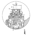
- the roller head illustrated in the drawings is a roller head used in the so-called PSW rolling mill (Planeten Schrägwalzwerk, planetary skew-rolling mill). Typically a PSW rolling mill includes three roller heads.
- the roller head 1 is arranged turnably in the rotor (not illustrated).
- the roller head 1 comprises a housing 8, inside which housing there is rotatably arranged a hollow outer axis 5 and means 2, 3, 4 for rotating said outer axis, as well as a center axis 6 arranged inside said outer axis, in a manner that transmits the rotary motion of said outer axis; said center axis 6 is movable in the axial direction and lockable in the axial direction, and it is also provided with a roller 7.
- a drive wheel 3 In the operating axis 2 of the roller head, there is arranged a drive wheel 3, the rotary motion whereof is transmitted by means of a counterwheel 4 to the hollow outer axis 5 of the roller head.
- the outer axis 5 is arranged rotatably inside the housing 8 of the roller head 1 by intermediation of bearing members 9, 10, 11.
- the outer axis 5 of the roller head is rotatably arranged in the roller head housing, at least by two radial-thrust bearings 9, 11, and by an axial bearing 10 provided therebetween.
- the roller 7 is arranged in the center axis 6.
- the roller head is characterized by an adjusting axis 16, which is arranged rotatably at that head of the outer axis 5 that is located at the opposite end with respect to the roller 7, said adjusting axis being essentially locked in the axial direction and comprising a counterpart 17 for the threaded section 15 provided in the center axis 6; said adjusting axis 16 includes a locking member 18, which in the locking position forms a friction coupling at least between the adjusting axis 16 and the outer axis 5.
- an adjusting axis 16 comprising a counterpart 17 for the threaded section 15 of the center axis 6.
- the position of the center axis 6 in the axial direction can be adjusted by turning the adjusting axis 16.
- the position of the center axis 6 is changed for a distance determined by the thread of the threaded section and the counterpart, depending on the volume of the rotary motion of the adjusting axis.
- the threads of the threaded section and the counterpart are extremely precise, for instance so-called trapezoidal threads.
- the adjusting axis 16 comprises a locking member, such as a sleeve member 18, whereby the adjusting axis can be steplessly locked in the outer axis 5.
- the locking member 18 is typically an expansible, pressure-operated sleeve member.
- the locking member 18 is a hydraulically operated sleeve member.
- the locking member 18 constitutes a uniform piece with the adjusting axis 16.
- the locking member can also be a separate sleeve member located between the outer axis 5 and the adjusting axis 16.
- the sleeve member 18 By means of the sleeve member 18, for instance the winding of the adjusting axis is prevented, and thus also the center axis 6 is locked in the axially adjusted position.
- the adjusting axis 16 comprises members, such as shoulders 19, 20, in order to prevent it from shifting in the axial direction, at least during the adjusting process.
- Figure 2 shows part of the roller head in cross-section.
- Figure 2 also shows a typical embodiment of the structure of the locking member 18.
- the locking member illustrated in the drawing is a so-called hydraulically operated sleeve member.
- a fluid channel system 21, 22, 23 with some hydraulic fluid provided therein.
- the sleeve 18 is at least partly expanded in the radial direction and attached, at the outer surface 18', to the countersurface, which in the case according to the invention is the typically cylindrical surface 5' located in the bore of the outer axis 5.
- the sleeve member 18 can form part of the adjusting axis 16, in which case it in the fastening position radially affects the outer axis 5 located outside said sleeve member, or it can be a separate sleeve member, in which case the sleeve member 18, by increasing pressure, radially affects the adjusting axis 16 located inside it, as well as the outer axis 5 located outside it.
- the invention is operated so that the adjusting axis 16 is locked, while the rolling mill center axis 6 is adjusted at a desired point, to the outer axis 5 by means of the locking member 18, most suitably by a friction coupling, in which case also the center axis 6 is locked in the axial direction.
- the expansive sleeve 18 serving as the locking member is pressurized by tightening the adjusting screw 24, so that the sleeve is expanded and forms a friction coupling.
- the adjusting screw 24 Is screwed open, in which case the sleeve 18 is contracted and the fiction coupling is released, and the adjusting axis 16 can again be turned.
- the axial motion of the rolling mill center axis 6 can be created and measured extremely accurately by providing, for the duration of the adjusting process, an Installation device 25 coupled to a measuring device 26.
- the installation device includes a torsion shaft 27 comprising a counterpart 29 for the driver 28 of the adjusting axis 16.
- the volume of the axial motion of the center axis is obtained when the size of the rotary motion of the adjusting axis is measured.
- the measuring device 26 is arranged to directly indicate the volume of the axial motion at a typical accuracy of for instance 0.01 mm.
- the roller head according to the invention By means of the roller head according to the invention, the axial adjustment Is carried out more accurately than in the prior art.
- the adjusting process is carried out quickly and precisely.
Landscapes
- Engineering & Computer Science (AREA)
- Mechanical Engineering (AREA)
- Rolls And Other Rotary Bodies (AREA)
- Reduction Rolling/Reduction Stand/Operation Of Reduction Machine (AREA)
- Friction Gearing (AREA)
- Support Of The Bearing (AREA)
- Retarders (AREA)
- Metal Rolling (AREA)
- Electrolytic Production Of Metals (AREA)
- Supporting Of Heads In Record-Carrier Devices (AREA)
- Crushing And Grinding (AREA)
Abstract
Description
Claims (8)
- A roller head for a planetary rolling arrangement, said roller head (1) comprising a housing (8), inside which housing there is rotatably arranged a hollow outer axis (5) and means (2, 3, 4), for rotating said outer axis, as well as inside said outer axis, in a manner that transmits the rotary motion thereof, a center axis (6), which is movable in the axial direction and can be locked in the axial direction, said center axis (6) being provided with a roller (7), characterized by an adjusting axis (16) which is rotatably arranged at the head of the outer axis (5) that is at the opposite end with respect to the roller (7) and essentially locked in the axial direction, said adjusting axis (16) being provided with a counterpart (17) for a threaded section (15) arranged in the center axis (6) and said adjusting axis also comprising a locking member (18), which in the locking position forms a friction coupling at least between the adjusting axis (16) and the outer axis (5).
- A roller head according to claim 1, characterized in that said locking member (18) is an expansible, pressure-operated member.
- A roller head according to claim 1 or 2, characterized in that said locking member (18) is a hydraulically operated sleeve member.
- A roller head according to any of the claims 1 - 3, characterized in that said locking member (18) constitutes a uniform piece with the adjusting axis (16).
- A roller head according to any of the claims 1 - 3, characterized in that said locking member is a separate sleeve member placed in between the outer axis (5) and the adjusting axis (16).
- A roller head according to any of the claims 1 - 5, characterized in that the threaded section (15) of the center axis is arranged in a bore (14) made in the center axis, in which case the counterpart (17) of the adjusting axis is a screw member.
- A roller head according to any of the claims 1 - 6, characterized in that the adjusting axis (16) is in the adjusting position arranged to adjust an installation device (25), which comprises a measuring device (26).
- A roller head according to any of the claims 1 - 7, characterized in that the outer axis (6) is rotatably arranged in the roller head housing at least by two radial-thrust bearings (9, 11) and by an axial bearing (10) provided therebetween.
Applications Claiming Priority (2)
| Application Number | Priority Date | Filing Date | Title |
|---|---|---|---|
| FI992740A FI109528B (en) | 1999-12-21 | 1999-12-21 | Rolling head for a planetary rolling device |
| FI992740 | 1999-12-21 |
Publications (3)
| Publication Number | Publication Date |
|---|---|
| EP1110632A2 true EP1110632A2 (en) | 2001-06-27 |
| EP1110632A3 EP1110632A3 (en) | 2003-12-10 |
| EP1110632B1 EP1110632B1 (en) | 2004-08-04 |
Family
ID=8555783
Family Applications (1)
| Application Number | Title | Priority Date | Filing Date |
|---|---|---|---|
| EP00104716A Expired - Lifetime EP1110632B1 (en) | 1999-12-21 | 2000-03-03 | Roller head for a planetary rolling mill |
Country Status (22)
| Country | Link |
|---|---|
| US (1) | US6666060B2 (en) |
| EP (1) | EP1110632B1 (en) |
| JP (1) | JP4732657B2 (en) |
| KR (1) | KR100717560B1 (en) |
| CN (1) | CN1167523C (en) |
| AT (1) | ATE272455T1 (en) |
| AU (1) | AU780876B2 (en) |
| BG (1) | BG64082B1 (en) |
| BR (1) | BR0016541A (en) |
| CA (1) | CA2393822C (en) |
| CZ (1) | CZ296614B6 (en) |
| DE (1) | DE60012675T2 (en) |
| EA (1) | EA003483B1 (en) |
| ES (1) | ES2224938T3 (en) |
| FI (1) | FI109528B (en) |
| MX (1) | MXPA02006041A (en) |
| PL (1) | PL197816B1 (en) |
| RS (1) | RS50106B (en) |
| SK (1) | SK285521B6 (en) |
| TR (1) | TR200201611T2 (en) |
| UA (1) | UA73755C2 (en) |
| WO (1) | WO2001045872A1 (en) |
Cited By (1)
| Publication number | Priority date | Publication date | Assignee | Title |
|---|---|---|---|---|
| DE102008022161A1 (en) * | 2008-05-05 | 2009-11-12 | Sms Meer Gmbh | Rolling device for the oblique rolling of tubular or rod-shaped rolling stock |
Families Citing this family (3)
| Publication number | Priority date | Publication date | Assignee | Title |
|---|---|---|---|---|
| IES20010399A2 (en) * | 2000-05-16 | 2002-02-06 | Richmount Computers Ltd | A protocol for a power supply unit controller |
| DE10349056A1 (en) * | 2003-10-17 | 2005-05-19 | Kocks Technik Gmbh & Co. Kg | Process for rolling rolling stock e.g. metal rods in a rolling mill comprises measuring the rotation of the rolling stock about its longitudinal direction, and controlling a drive parameter of a planetary cross rolling mill |
| CN106180198B (en) * | 2016-08-10 | 2018-04-10 | 无锡隆达金属材料有限公司 | A kind of roller roller head unit of planetary rolling three |
Family Cites Families (13)
| Publication number | Priority date | Publication date | Assignee | Title |
|---|---|---|---|---|
| DE2748770A1 (en) * | 1970-03-03 | 1979-05-10 | Schloemann Siemag Ag | Roll head with bevel rollers - has coupling bushings with intermediate position disengaging adjusting bushing from hollow shaft |
| DE2009867C3 (en) * | 1970-03-03 | 1978-08-03 | Schloemann-Siemag Ag, 4000 Duesseldorf | Rolling head with overhung rolls inclined towards the rolling stock axis |
| DE2723506A1 (en) * | 1977-05-25 | 1978-12-14 | Kabel Metallwerke Ghh | INCLINED ROLLING MILL FOR REDUCING LONG DISTURBED GOOD |
| US3735617A (en) * | 1970-10-19 | 1973-05-29 | Siemag Siegener Masch Bau | Rolling mill |
| DE3125682C2 (en) * | 1980-08-08 | 1986-11-27 | SMS Schloemann-Siemag AG, 4000 Düsseldorf | Rolling head of a cross rolling mill |
| ES503781A0 (en) * | 1980-08-08 | 1982-06-01 | Schloemann Siemag Ag | IMPROVEMENTS IN LAMINATION HEADS OF AN OBLIQUE LAMINATOR |
| JPS58157508A (en) * | 1982-03-10 | 1983-09-19 | Kawasaki Heavy Ind Ltd | Construction of roll head of planetary type skew rolling mill |
| DE3229211A1 (en) * | 1982-08-05 | 1984-02-09 | SMS Schloemann-Siemag AG, 4000 Düsseldorf | ROLLING HEAD OF A PLANETE SCHRAEG ROLLING MILL |
| JPS60240312A (en) * | 1984-05-14 | 1985-11-29 | Kawasaki Heavy Ind Ltd | Roll screw-down device for planetary type cross helical rolling mill |
| DE3531529A1 (en) | 1985-09-04 | 1987-03-12 | Schloemann Siemag Ag | Rolling head for planetary skew rolling mills |
| JP2580098B2 (en) * | 1992-04-06 | 1997-02-12 | 新日本製鐵株式会社 | Bar and tube rolling equipment |
| DE19510715C2 (en) * | 1995-03-24 | 2002-08-29 | Kocks Technik | Device for cross-rolling of tubular or rod-shaped rolling stock |
| DE19711257A1 (en) | 1997-03-18 | 1998-09-24 | Schloemann Siemag Ag | Sensor for a planetary skew rolling mill as a CCD camera |
-
1999
- 1999-12-21 FI FI992740A patent/FI109528B/en not_active IP Right Cessation
-
2000
- 2000-03-03 EP EP00104716A patent/EP1110632B1/en not_active Expired - Lifetime
- 2000-03-03 DE DE60012675T patent/DE60012675T2/en not_active Expired - Lifetime
- 2000-03-03 ES ES00104716T patent/ES2224938T3/en not_active Expired - Lifetime
- 2000-03-03 AT AT00104716T patent/ATE272455T1/en active
- 2000-12-20 CZ CZ20021993A patent/CZ296614B6/en not_active IP Right Cessation
- 2000-12-20 AU AU23793/01A patent/AU780876B2/en not_active Ceased
- 2000-12-20 MX MXPA02006041A patent/MXPA02006041A/en active IP Right Grant
- 2000-12-20 JP JP2001546806A patent/JP4732657B2/en not_active Expired - Fee Related
- 2000-12-20 KR KR1020027007862A patent/KR100717560B1/en not_active Expired - Fee Related
- 2000-12-20 CN CNB008176426A patent/CN1167523C/en not_active Expired - Lifetime
- 2000-12-20 RS YUP-481/02A patent/RS50106B/en unknown
- 2000-12-20 UA UA2002065196A patent/UA73755C2/en unknown
- 2000-12-20 US US10/168,186 patent/US6666060B2/en not_active Expired - Lifetime
- 2000-12-20 PL PL355661A patent/PL197816B1/en unknown
- 2000-12-20 TR TR2002/01611T patent/TR200201611T2/en unknown
- 2000-12-20 BR BR0016541-7A patent/BR0016541A/en not_active IP Right Cessation
- 2000-12-20 CA CA002393822A patent/CA2393822C/en not_active Expired - Lifetime
- 2000-12-20 WO PCT/FI2000/001124 patent/WO2001045872A1/en not_active Ceased
- 2000-12-20 EA EA200200674A patent/EA003483B1/en not_active IP Right Cessation
- 2000-12-20 SK SK858-2002A patent/SK285521B6/en not_active IP Right Cessation
-
2002
- 2002-06-10 BG BG106808A patent/BG64082B1/en unknown
Cited By (1)
| Publication number | Priority date | Publication date | Assignee | Title |
|---|---|---|---|---|
| DE102008022161A1 (en) * | 2008-05-05 | 2009-11-12 | Sms Meer Gmbh | Rolling device for the oblique rolling of tubular or rod-shaped rolling stock |
Also Published As
Similar Documents
| Publication | Publication Date | Title |
|---|---|---|
| US20040033851A1 (en) | Continuously variable transmission (CVT) assembly and method of axially positioning pulley members of a CVT | |
| CA1081546A (en) | Backup roll for thin walled pipe grooving device | |
| KR101075336B1 (en) | Calibration device and method of round tube | |
| DE2238428A1 (en) | BEARING CONSTRUCTION | |
| EP1110632B1 (en) | Roller head for a planetary rolling mill | |
| DE19502918B4 (en) | Apparatus for the continuous production of longitudinally welded thin-walled helical or annular corrugated metal pipes | |
| DE3825505C2 (en) | Device for monitoring and controlling a tire inflation pressure in a tire testing machine | |
| US10124380B2 (en) | Device for adjusting a roll in a roll stand | |
| CN110530304B (en) | Device for detecting the diameter runout of the flange end of the inner ring of the non-driving wheel hub bearing unit | |
| US4275530A (en) | Grinding heads for grinding machines | |
| JPH08257609A (en) | Device for tilt rolling of tubular or rod-shaped rolled material | |
| JP4430823B2 (en) | Support roll or intermediate roll used in a rolling mill for rolling flat rolled material | |
| US6038907A (en) | Straightening machine for rolled beams | |
| EP0129633A1 (en) | A mounting for a roll unit, particularly in a wire rod mill | |
| JPH04506771A (en) | Metal wire straightening device | |
| SU438453A1 (en) | Swath roll mill | |
| SU1117199A1 (en) | Apparatus for automatic fine adjustment of axial tool | |
| JPH0750004Y2 (en) | Roll width adjustment device | |
| SU1740976A1 (en) | Device for check of diameter of article | |
| SU1271670A1 (en) | Boring head | |
| JPS5937701B2 (en) | thread rolling machine | |
| JPS61169105A (en) | Roll width adjusting device | |
| JPH05277512A (en) | Friction drive type inclined rolling mill |
Legal Events
| Date | Code | Title | Description |
|---|---|---|---|
| PUAI | Public reference made under article 153(3) epc to a published international application that has entered the european phase |
Free format text: ORIGINAL CODE: 0009012 |
|
| AK | Designated contracting states |
Kind code of ref document: A2 Designated state(s): AT BE CH CY DE DK ES FI FR GB GR IE IT LI LU MC NL PT SE |
|
| AX | Request for extension of the european patent |
Free format text: AL;LT;LV;MK;RO;SI |
|
| PUAL | Search report despatched |
Free format text: ORIGINAL CODE: 0009013 |
|
| AK | Designated contracting states |
Kind code of ref document: A3 Designated state(s): AT BE CH CY DE DK ES FI FR GB GR IE IT LI LU MC NL PT SE |
|
| AX | Request for extension of the european patent |
Extension state: AL LT LV MK RO SI |
|
| GRAP | Despatch of communication of intention to grant a patent |
Free format text: ORIGINAL CODE: EPIDOSNIGR1 |
|
| 17P | Request for examination filed |
Effective date: 20031127 |
|
| GRAS | Grant fee paid |
Free format text: ORIGINAL CODE: EPIDOSNIGR3 |
|
| GRAA | (expected) grant |
Free format text: ORIGINAL CODE: 0009210 |
|
| AK | Designated contracting states |
Kind code of ref document: B1 Designated state(s): AT BE CH CY DE DK ES FI FR GB GR IE IT LI LU MC NL PT SE |
|
| AX | Request for extension of the european patent |
Extension state: AL LT LV MK RO SI |
|
| PG25 | Lapsed in a contracting state [announced via postgrant information from national office to epo] |
Ref country code: FI Free format text: LAPSE BECAUSE OF FAILURE TO SUBMIT A TRANSLATION OF THE DESCRIPTION OR TO PAY THE FEE WITHIN THE PRESCRIBED TIME-LIMIT Effective date: 20040804 |
|
| REG | Reference to a national code |
Ref country code: GB Ref legal event code: FG4D |
|
| REG | Reference to a national code |
Ref country code: CH Ref legal event code: NV Representative=s name: KATZAROV S.A. Ref country code: CH Ref legal event code: EP |
|
| REG | Reference to a national code |
Ref country code: SE Ref legal event code: TRGR |
|
| AKX | Designation fees paid |
Designated state(s): AT BE CH CY DE DK ES FI FR GB GR IE IT LI LU MC NL PT SE |
|
| REG | Reference to a national code |
Ref country code: IE Ref legal event code: FG4D |
|
| REF | Corresponds to: |
Ref document number: 60012675 Country of ref document: DE Date of ref document: 20040909 Kind code of ref document: P |
|
| PG25 | Lapsed in a contracting state [announced via postgrant information from national office to epo] |
Ref country code: DK Free format text: LAPSE BECAUSE OF FAILURE TO SUBMIT A TRANSLATION OF THE DESCRIPTION OR TO PAY THE FEE WITHIN THE PRESCRIBED TIME-LIMIT Effective date: 20041104 |
|
| REG | Reference to a national code |
Ref country code: GR Ref legal event code: EP Ref document number: 20040403181 Country of ref document: GR |
|
| PG25 | Lapsed in a contracting state [announced via postgrant information from national office to epo] |
Ref country code: CY Free format text: LAPSE BECAUSE OF FAILURE TO SUBMIT A TRANSLATION OF THE DESCRIPTION OR TO PAY THE FEE WITHIN THE PRESCRIBED TIME-LIMIT Effective date: 20050303 Ref country code: IE Free format text: LAPSE BECAUSE OF NON-PAYMENT OF DUE FEES Effective date: 20050303 Ref country code: LU Free format text: LAPSE BECAUSE OF NON-PAYMENT OF DUE FEES Effective date: 20050303 |
|
| REG | Reference to a national code |
Ref country code: ES Ref legal event code: FG2A Ref document number: 2224938 Country of ref document: ES Kind code of ref document: T3 |
|
| PG25 | Lapsed in a contracting state [announced via postgrant information from national office to epo] |
Ref country code: MC Free format text: LAPSE BECAUSE OF NON-PAYMENT OF DUE FEES Effective date: 20050331 |
|
| ET | Fr: translation filed | ||
| PLBE | No opposition filed within time limit |
Free format text: ORIGINAL CODE: 0009261 |
|
| STAA | Information on the status of an ep patent application or granted ep patent |
Free format text: STATUS: NO OPPOSITION FILED WITHIN TIME LIMIT |
|
| 26N | No opposition filed |
Effective date: 20050506 |
|
| REG | Reference to a national code |
Ref country code: IE Ref legal event code: MM4A |
|
| PG25 | Lapsed in a contracting state [announced via postgrant information from national office to epo] |
Ref country code: PT Free format text: LAPSE BECAUSE OF NON-PAYMENT OF DUE FEES Effective date: 20050104 |
|
| REG | Reference to a national code |
Ref country code: FR Ref legal event code: PLFP Year of fee payment: 16 |
|
| REG | Reference to a national code |
Ref country code: FR Ref legal event code: PLFP Year of fee payment: 17 |
|
| REG | Reference to a national code |
Ref country code: DE Ref legal event code: R082 Ref document number: 60012675 Country of ref document: DE Representative=s name: K & H BONAPAT PATENTANWAELTE KOCH VON BEHREN &, DE Ref country code: DE Ref legal event code: R082 Ref document number: 60012675 Country of ref document: DE Representative=s name: K & H BONAPAT PATENTANWAELTE KOCH - VON BEHREN, DE Ref country code: DE Ref legal event code: R081 Ref document number: 60012675 Country of ref document: DE Owner name: LUVATA ESPOO OY, FI Free format text: FORMER OWNER: OUTOKUMPU OYJ, ESPOO, FI Ref country code: DE Ref legal event code: R081 Ref document number: 60012675 Country of ref document: DE Owner name: LUVATA ALLTOP (ZHONGSHAN) LTD., ZHONGSHAN, CN Free format text: FORMER OWNER: OUTOKUMPU OYJ, ESPOO, FI |
|
| REG | Reference to a national code |
Ref country code: CH Ref legal event code: PUE Owner name: LUVATA ESPOO OY, FI Free format text: FORMER OWNER: OUTOKUMPU OYJ, FI |
|
| REG | Reference to a national code |
Ref country code: NL Ref legal event code: PD Owner name: LUVATA ESPOO OY; FI Free format text: DETAILS ASSIGNMENT: CHANGE OF OWNER(S), ASSIGNMENT; FORMER OWNER NAME: OUTOKUMPU OYJ Effective date: 20161213 |
|
| REG | Reference to a national code |
Ref country code: ES Ref legal event code: PC2A Owner name: LUVATA ESPOO OY Effective date: 20170201 |
|
| REG | Reference to a national code |
Ref country code: DE Ref legal event code: R082 Ref document number: 60012675 Country of ref document: DE Representative=s name: K & H BONAPAT PATENTANWAELTE KOCH VON BEHREN &, DE Ref country code: DE Ref legal event code: R082 Ref document number: 60012675 Country of ref document: DE Representative=s name: K & H BONAPAT PATENTANWAELTE KOCH - VON BEHREN, DE Ref country code: DE Ref legal event code: R081 Ref document number: 60012675 Country of ref document: DE Owner name: LUVATA ALLTOP (ZHONGSHAN) LTD., ZHONGSHAN, CN Free format text: FORMER OWNER: LUVATA ESPOO OY, ESPOO, FI |
|
| REG | Reference to a national code |
Ref country code: CH Ref legal event code: PUE Owner name: LUVATA ALLTOP (ZHONGSHAN) LTD, CN Free format text: FORMER OWNER: LUVATA ESPOO OY, FI |
|
| REG | Reference to a national code |
Ref country code: GB Ref legal event code: 732E Free format text: REGISTERED BETWEEN 20170126 AND 20170201 Ref country code: NL Ref legal event code: PD Owner name: LUVATA ALLTOP (ZHONGSHAN) LTD; CN Free format text: DETAILS ASSIGNMENT: CHANGE OF OWNER(S), ASSIGNMENT; FORMER OWNER NAME: OUTOKUMPU OYJ Effective date: 20170207 |
|
| REG | Reference to a national code |
Ref country code: ES Ref legal event code: PC2A Owner name: LUVATA ALLTOP(ZHONGSHAN) LTD. Effective date: 20170315 Ref country code: FR Ref legal event code: PLFP Year of fee payment: 18 |
|
| REG | Reference to a national code |
Ref country code: AT Ref legal event code: PC Ref document number: 272455 Country of ref document: AT Kind code of ref document: T Owner name: LUVATA ALLTOP (ZHONGSHAN) LTD., CN Effective date: 20170301 |
|
| REG | Reference to a national code |
Ref country code: GB Ref legal event code: 732E Free format text: REGISTERED BETWEEN 20170406 AND 20170412 |
|
| REG | Reference to a national code |
Ref country code: FR Ref legal event code: TP Owner name: LUVATA ESPOO OY, FI Effective date: 20170601 |
|
| REG | Reference to a national code |
Ref country code: FR Ref legal event code: TP Owner name: LUVATA ALLTOP (ZHONGSHAN) LTD, CN Effective date: 20170728 |
|
| REG | Reference to a national code |
Ref country code: CH Ref legal event code: PCAR Free format text: NEW ADDRESS: AVENUE DES MORGINES 12, 1213 PETIT-LANCY (CH) |
|
| REG | Reference to a national code |
Ref country code: FR Ref legal event code: PLFP Year of fee payment: 19 |
|
| PGFP | Annual fee paid to national office [announced via postgrant information from national office to epo] |
Ref country code: IT Payment date: 20190325 Year of fee payment: 20 Ref country code: DE Payment date: 20190321 Year of fee payment: 20 Ref country code: GB Payment date: 20190320 Year of fee payment: 20 Ref country code: CH Payment date: 20190320 Year of fee payment: 20 Ref country code: FR Payment date: 20190322 Year of fee payment: 20 |
|
| PGFP | Annual fee paid to national office [announced via postgrant information from national office to epo] |
Ref country code: BE Payment date: 20190320 Year of fee payment: 20 Ref country code: NL Payment date: 20190320 Year of fee payment: 20 Ref country code: AT Payment date: 20190321 Year of fee payment: 20 Ref country code: SE Payment date: 20190320 Year of fee payment: 20 Ref country code: GR Payment date: 20190326 Year of fee payment: 20 |
|
| PGFP | Annual fee paid to national office [announced via postgrant information from national office to epo] |
Ref country code: ES Payment date: 20190418 Year of fee payment: 20 |
|
| REG | Reference to a national code |
Ref country code: DE Ref legal event code: R071 Ref document number: 60012675 Country of ref document: DE |
|
| REG | Reference to a national code |
Ref country code: CH Ref legal event code: PL |
|
| REG | Reference to a national code |
Ref country code: GB Ref legal event code: PE20 Expiry date: 20200302 |
|
| REG | Reference to a national code |
Ref country code: AT Ref legal event code: MK07 Ref document number: 272455 Country of ref document: AT Kind code of ref document: T Effective date: 20200303 |
|
| REG | Reference to a national code |
Ref country code: BE Ref legal event code: MK Effective date: 20200303 |
|
| PG25 | Lapsed in a contracting state [announced via postgrant information from national office to epo] |
Ref country code: GB Free format text: LAPSE BECAUSE OF EXPIRATION OF PROTECTION Effective date: 20200302 |
|
| REG | Reference to a national code |
Ref country code: SE Ref legal event code: EUG |
|
| REG | Reference to a national code |
Ref country code: NL Ref legal event code: MK Effective date: 20200302 |
|
| REG | Reference to a national code |
Ref country code: ES Ref legal event code: FD2A Effective date: 20200803 |
|
| PG25 | Lapsed in a contracting state [announced via postgrant information from national office to epo] |
Ref country code: ES Free format text: LAPSE BECAUSE OF EXPIRATION OF PROTECTION Effective date: 20200304 |