EP1110497A2 - Dishwasher - Google Patents
Dishwasher Download PDFInfo
- Publication number
- EP1110497A2 EP1110497A2 EP00830802A EP00830802A EP1110497A2 EP 1110497 A2 EP1110497 A2 EP 1110497A2 EP 00830802 A EP00830802 A EP 00830802A EP 00830802 A EP00830802 A EP 00830802A EP 1110497 A2 EP1110497 A2 EP 1110497A2
- Authority
- EP
- European Patent Office
- Prior art keywords
- basket
- connecting pipe
- inlet nozzle
- dishwasher according
- actuating
- Prior art date
- Legal status (The legal status is an assumption and is not a legal conclusion. Google has not performed a legal analysis and makes no representation as to the accuracy of the status listed.)
- Withdrawn
Links
Images



Classifications
-
- A—HUMAN NECESSITIES
- A47—FURNITURE; DOMESTIC ARTICLES OR APPLIANCES; COFFEE MILLS; SPICE MILLS; SUCTION CLEANERS IN GENERAL
- A47L—DOMESTIC WASHING OR CLEANING; SUCTION CLEANERS IN GENERAL
- A47L15/00—Washing or rinsing machines for crockery or tableware
- A47L15/42—Details
- A47L15/50—Racks ; Baskets
- A47L15/508—Hydraulic connections for racks
-
- A—HUMAN NECESSITIES
- A47—FURNITURE; DOMESTIC ARTICLES OR APPLIANCES; COFFEE MILLS; SPICE MILLS; SUCTION CLEANERS IN GENERAL
- A47L—DOMESTIC WASHING OR CLEANING; SUCTION CLEANERS IN GENERAL
- A47L15/00—Washing or rinsing machines for crockery or tableware
- A47L15/14—Washing or rinsing machines for crockery or tableware with stationary crockery baskets and spraying devices within the cleaning chamber
- A47L15/18—Washing or rinsing machines for crockery or tableware with stationary crockery baskets and spraying devices within the cleaning chamber with movably-mounted spraying devices
- A47L15/22—Rotary spraying devices
- A47L15/23—Rotary spraying devices moved by means of the sprays
Definitions
- the invention relates to a dishwasher, comprising at least one compartment for loading the dishes which can be opened and inside which a dish loading basket is housed, which basket has a rotating spraying element and can be extracted at least partly from the loading compartment, there being provided means for supplying the water or other fluid to the rotating spraying element, which are mounted in the loading compartment and which have a supply nozzle, and the rotor being associated with the basket and extractable together therewith and also provided with an inlet nozzle, while automatic engagement and disengagement means are provided between the two nozzles.
- Dishwashers are generally provided with two dish-carrying baskets which can be extracted from the loading compartment so as to allow loading and unloading of the plates or other dishes.
- said machines are provided with at least one rotor, generally two or more spraying rotors, which are arranged at predetermined different levels and at least one of which is integral with the basket and is displaced towards the outside during the extracting movement of the said basket.
- the spraying rotor has means for automatic connection and disconnection to the fluid supply system associated with the machine when the basket is displaced towards the outside and towards the inside of the dishwasher.
- the invention relates to automatic connection means which are implroved compared to those which are currently known and which allow improved and more reliable engagement and disengagement of the supply pipe parts of the spraying rotor, one of which is integral with the machine and the other with the basket. All ofwhich by means of a simple, robust and low-cost structure.
- the invention achieves the above-mentioned objects using automatic engagement and disengagement means which are operated by means of cam or inclined-surface tracks associated with one of the two nozzles and actuating means co-operating with said tracks and associated with the other part, so as to produce displacements of an intermediate connecting pipe from a position for connecting the two nozzles together, into a position for disconnecting the said connecting pipe from at least one of the two nozzles, said displacements being simultaneous and effected by the insertion and extraction movement of the loading basket within the loading compartment.
- the connecting pipe (3) can be engaged with and disengaged from the opening of the inlet nozzle (2) associated with the basket, owing to the actuating movement caused by the said basket (5) and owing to funnel-type means for guiding into the engaged position.
- a preferred embodiment envisages a dishwasher of the type described initially, in which he automatic engagement and disengagement means consist of an angled connecting pipe mounted so as to be sealingly slidable with one of its arms on the supply nozzle, the supply nozzle being oriented transversely with respect to the direction of extraction and insertion of the basket and the other arm of the connecting pipe being oriented in a transverse direction with respect to the first arm and towards an engaging end of the inlet nozzle associated with the basket, while in the extracted condition of the basket the connecting pipe assumes, with its arm engaging with the inlet nozzle of the basket, a staggered position with respect to the latter and there being provided, co-operating, automatic actuating means for sliding the connecting pipe into the centred position of engagement with the inlet nozzle associated with the basket, which automatic actuating means are associated with the connecting pipe and the basket and bring the connecting pipe into the position of engagement with the inlet nozzle during the inwards movement of the said basket.
- the connecting pipe is mounted so as to be vertically slidable downwards on the supply nozzle which is also vertical, through displacement by means of gravity.
- the automatic actuating means consist of an actuating cam on a slidable element integral with the connecting pipe and co-operate with a thruster associated with the basket in such a way that the sliding of the baskets in the extraction direction and in the insertion direction causes vertically sliding displacements of the connecting pipe in two mutually opposite directions.
- the actuating cam consists of an inclined surface.
- the inclination is preferably between 300 and 500 relative to the axis of sliding of the basket in the extraction/insertion direction.
- the downwards displacement of the connecting pipe during extraction of the basket is aided by resilient elements, such as springs or the like operating by means of compression and/or traction.
- the inlet nozzle associated with the basket has a mouth for engagement of the end of the associated arm of the connecting pipe, which is conically flared.
- the conical flaring has different inclinations, the inclination of the part facing the inclined surface being substantially parallel to that of the said inclined surface.
- the connecting pipe integral with the inclined actuating surface is slidably guided only by the supply nozzle associated with the machine loading compartment.
- the inclined actuating surface and the connecting pipe are mounted on a sliding shoe which slides on guides outside the connecting pipe.
- the inclined actuating surface and the sliding shoe, where present, integral with the angled connecting pipe and the said inclined actuating surface are on the outside of the connecting pipe and are provided in a central position above the dishwasher so as not to interfere with the dishes housed in the basket.
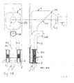
- a dishwasher has in its housing compartment at least one basket, a vertical supply nozzle 1 for the washing fluid which may be simple rinsing water or a solution of water and detergent or other substance with a washing or other function.
- the basket (not shown in detail) which can be extracted from and inserted into the dishwasher with a sliding movement in the direction of the arrow F, for example, as is known, via lateral guides or other means, has, associated with it, at least one spraying rotor (not shown), which is mounted on the basket in a stable manner and has a plurality of spraying nozzles.
- the spraying rotor has an inlet nozzle 2 which is integral with the basket and which must be engaged with and disengaged from the supply nozzle 1, during introduction of the basket into the loading compartment and during extraction thereof, respectively.
- the inlet nozzle 2 is oriented in a direction parallel to the direction of extraction/insertion of the carriage [sic] and in particular perpendicular to he direction of the axis of the supply nozzle.
- the two nozzles 1, 2 are arranged with their axes substantially in the same vertical plane.
- the supply nozzle 1 integral with the basket housing compartment has, slidably mounted on it by means of a sliding seal 103, an angled connecting pipe 3 which has an arm 203 and an arm 303, which arms are oriented respectively with their axes parallel to the supply nozzle 1 and the inlet nozzle 2.
- the connecting pipe 3 has, integral with it, in a position above the arm for engagement with the inlet nozzle 2, an inclined raising actuating surface 104 of an actuating element 4.
- the actuating element 4 is centred with respect to the arm 303 of the angled connecting pipe 3.
- the inclined sliding actuating surface of the connecting pipe 3 on the supply nozzle 1 has an inclination which is substantially between 300 and 500 relative to the horizontal plane and said surface co-operates with a rounded actuating element 105 mounted on the free end of the inlet nozzle 2.
- this free end consists of a conical flaring, the external upper rounded lip 105 of which co-operates with an inclined surface 104 so as to raise the connecting pipe 3, with the arm 303 in a position coaxial with the inlet nozzle 2 during the gradual inwards sliding movement of the basket.
- the conical flaring has, in the bottom zone, an inclination substantially corresponding to or parallel with that of the inclined actuating surface 104.
- the conical flaring 5 is asymmetrical, namely has different inclinations on the two diametrically opposite sides.
- the conical flaring 5 terminates, at the opening of the inlet nozzle 2, with a seal 305 inside which the arm 303 of the connecting pipe 303 [sic] is automatically engageable in a sealed manner by means of the end inserting section of the basket, as shown in Fig. 4.
- Figs. 2, 3A and 3B consist firstly in providing resilient means, i.e. springs 6 which push the connecting pipe in the sliding direction downwards, thus aiding the force of gravity.
- the abutments for the s prings have engaging extensions 8 onto which the spring is mounted so that it can be retained in position.
- the variation according to Figs. 3A and 3B envisages two springs which operate in the opposite direction to compression, i.e. in the tensile direction, and are arranged on the two diametrically opposite sides of the connecting pipe 3, i.e. the arm 203 of the latter.
- the two springs are located between abutments 7 and 9 integral, respectively, with the basket housing compartment and the vertical arm 203 of the connecting pipe 3.
- Fig. 3B also illustrates the characteristic feature whereby the inclined actuating surface 104 may be advantageously centred with the connecting pipe.
- This characteristic feature as well as moreover other characteristic features described with reference to Fig. 1, may be freely used in combination with the further specific constructional examples.
- the extracting and inserting displacement of the basket automatically operates the means for engagement of the supply nozzle 1 with the inlet nozzle 2 of the spraying rotor associated with the basket.
- the position of the inclined actuating surface far from the basket ensures that there is no interference with the dishes housed therein.
- the extreme simplicity and economical design ensure reliable operation, without the need for constant or repeated maintenance.
- the invention is not limited to that described and illustrated, but may be varied from a constructional point of view without departing from the basic principle described above and claimed below.
Landscapes
- Washing And Drying Of Tableware (AREA)
- Detergent Compositions (AREA)
Abstract
Description
Claims (11)
- Dishwasher, comprising at least one dish-loading compartment which can be opened and which houses a dish-loading basket, which basket has a rotating spraying element and can be extracted at least partly from the loading compartment, means (1) being provided for supplying the water or other fluid to the rotating spraying element, which means are mounted in the loading compartment and have a supply nozzle, the rotor associated with the basket and able to be extracted together therewith also being provided with an inlet nozzle (2), while automatic engagement and disengagement means (3, 4, 5) are provided between the two nozzles, characterized in that the automatic engagement and disengagement means are operated by means of cam or inclined-surface tracks associated with one of the two nozzles (1, 2) and actuating means co-operating with said tracks and associated with the other part (2, 1), so as to produce displacements of an intermediate connecting pipe (3) from a position for connecting the two nozzles (1, 2) together, into a position for disconnecting the said connecting pipe (3) from at least one of the two nozzles (1, 2), said displacements being simultaneous and effected by the insertion and extraction movement of the loading basket within the loading compartment.
- Dishwasher according to Claim 1, characterized in that the connecting pipe (3) may be engaged with and disengaged from the opening of the inlet nozzle (2) associated with the basket, by means of the actuating movement caused by the said basket (5) and by means of funnel-shaped means for guiding into the engaged position.
- Dishwasher according to Claim 1 or 2, characterized in that the automatic engagement or disengagement means consist of an angled connecting pipe (3) which is mounted with an arm (103) sliding in a sealed manner on the supply nozzle (2) [sic], the supply nozzle (2) [sic] being oriented transversely with respect to the direction of extraction and insertion of the basket and the other arm (303) of the connecting pipe (3) being oriented in a transverse direction with respect to the first arm and towards an engaging end of the inlet nozzle (2) associated with the basket, while in the extracted condition of the basket the connecting pipe (3) assumes, with its arm (303) for engagement with the inlet nozzle (2) of the basket, a staggered position with respect to the latter and there being provided, co-operating, means (104, 105) for automatic sliding actuation of the connecting pipe (3) into the centred position for engagement with the inlet nozzle (2) associated with the basket, which automatic actuating means are associated partly with the connecting pipe (3) and partly with the basket and move the connecting pipe (3) into the position where it is engaged with the inlet nozzle (2) during the inwards movement of the said basket.
- Dishwasher according to one or more of the preceding claims, characterized in that the connecting pipe (3) is mounted so as to slide vertically downwards on the supply nozzle (1) which is also vertical, owing to displacement by means of gravity.
- Dishwasher according to one or more of the preceding claims, characterized in that the automatic actuating means consist of an actuating cam (4, 104) on a sliding element integral with the connecting pipe (3) and co-operating with a thruster (5, 105) associated with the basket so that the sliding of the basket in the extraction direction and in the insertion direction causes vertical sliding displacements of the connecting pipe (3) in two mutually opposite directions and between two predetermined levels, one of which, in particular the upper level, corresponds to the position for coaxial engagement with the inlet nozzle (2).
- Dishwasher according to one or more of the preceding claims, characterized in that actuating cam consists of an inclined surface (104).
- Dishwasher according to Claim 6, characterized in that the inclination of the inclined surface (104) is preferably between 300 and 500 relative to the sliding axis of the basket in the direction of extraction/insertion.
- Dishwasher according to one or more of the preceding claims, characterized in that the downwards displacement of the connecting pipe (3) during extraction of the basket is aided by resilient elements, such as springs or the like (6), which operate by means of compression and/or traction
- Dishwasher according to one or more of the preceding claims, characterized in that the inlet nozzle (2) associated with the basket has a mouth (5) for engagement of the end of the associated arm (303) of the connecting pipe (3), which is conically flared.
- Dishwasher according to one or more of the preceding claims, characterized in that the conical flaring (5) has different inclinations, the inclination of the part facing the inclined surface (104) being substantially parallel to that of the said inclined surface and the bottom edge of the connecting pipe, i.e. of the arm for engagement with the inlet nozzle (2), being intended to co-operate with or slide on said inclined conical surface.
- Dishwasher according to one or more of the preceding claims, characterized in that the inclined actuating surface (104) and the sliding shoe, where present, integral with the angular connecting pipe (3) and the said inclined actuating surface (104) are located outside the connecting pipe and are provided in a central position above this connecting pipe (3) and in any case in such a way as not to interfere with the dishes housed in the basket.
Applications Claiming Priority (2)
| Application Number | Priority Date | Filing Date | Title |
|---|---|---|---|
| IT1999BO000688A IT1311433B1 (en) | 1999-12-17 | 1999-12-17 | DISHWASHER. |
| ITBO990688 | 1999-12-17 |
Publications (2)
| Publication Number | Publication Date |
|---|---|
| EP1110497A2 true EP1110497A2 (en) | 2001-06-27 |
| EP1110497A3 EP1110497A3 (en) | 2002-10-02 |
Family
ID=11344417
Family Applications (1)
| Application Number | Title | Priority Date | Filing Date |
|---|---|---|---|
| EP00830802A Withdrawn EP1110497A3 (en) | 1999-12-17 | 2000-12-05 | Dishwasher |
Country Status (2)
| Country | Link |
|---|---|
| EP (1) | EP1110497A3 (en) |
| IT (1) | IT1311433B1 (en) |
Cited By (9)
| Publication number | Priority date | Publication date | Assignee | Title |
|---|---|---|---|---|
| EP1358834A3 (en) * | 2002-05-03 | 2005-08-10 | Whirlpool Corporation | In-sink dishwasher with self-aligning liquid feed system |
| WO2005107569A1 (en) * | 2004-05-03 | 2005-11-17 | Miele & Cie. Kg | Dishwasher with a height-adjustable upper basket |
| DE102006055348A1 (en) * | 2006-11-23 | 2008-05-29 | BSH Bosch und Siemens Hausgeräte GmbH | dishwasher |
| EP1935322A3 (en) * | 2006-12-22 | 2009-03-11 | BSH Bosch und Siemens Hausgeräte GmbH | Dish washer |
| EP3047785A1 (en) * | 2015-01-22 | 2016-07-27 | Miele & Cie. KG | Dishwasher, in particular household dishwasher |
| US9480389B2 (en) | 2013-06-24 | 2016-11-01 | Wolf Appliance, Inc. | Connector for a dishwasher middle spray arm |
| DE102017114185A1 (en) | 2016-07-01 | 2018-01-04 | Miele & Cie. Kg | Dishwasher, in particular household dishwasher |
| CN113413108A (en) * | 2020-03-02 | 2021-09-21 | 佛山市顺德区美的洗涤电器制造有限公司 | Spout subassembly and domestic appliance |
| WO2026017681A1 (en) * | 2024-07-18 | 2026-01-22 | BSH Hausgeräte GmbH | Dishwasher |
Family Cites Families (2)
| Publication number | Priority date | Publication date | Assignee | Title |
|---|---|---|---|---|
| DE2355271A1 (en) * | 1973-11-06 | 1975-05-07 | Licentia Gmbh | Dishwasher with spray arm feed pipe - is loosely coupled to water feed duct attached fast to housing |
| DE2732665C2 (en) * | 1977-07-20 | 1983-01-05 | Bosch-Siemens Hausgeräte GmbH, 7000 Stuttgart | A crockery basket with a spray arm that can be inserted into the washing compartment of a dishwasher at different heights |
-
1999
- 1999-12-17 IT IT1999BO000688A patent/IT1311433B1/en active
-
2000
- 2000-12-05 EP EP00830802A patent/EP1110497A3/en not_active Withdrawn
Cited By (13)
| Publication number | Priority date | Publication date | Assignee | Title |
|---|---|---|---|---|
| EP1358834A3 (en) * | 2002-05-03 | 2005-08-10 | Whirlpool Corporation | In-sink dishwasher with self-aligning liquid feed system |
| WO2005107569A1 (en) * | 2004-05-03 | 2005-11-17 | Miele & Cie. Kg | Dishwasher with a height-adjustable upper basket |
| DE102006055348A1 (en) * | 2006-11-23 | 2008-05-29 | BSH Bosch und Siemens Hausgeräte GmbH | dishwasher |
| WO2008061883A1 (en) * | 2006-11-23 | 2008-05-29 | BSH Bosch und Siemens Hausgeräte GmbH | Dishwasher having height adjustable connecting tube |
| DE102006055348B4 (en) * | 2006-11-23 | 2008-09-04 | BSH Bosch und Siemens Hausgeräte GmbH | dishwasher |
| CN101204314B (en) * | 2006-12-22 | 2013-04-03 | Bsh博世和西门子家用器具有限公司 | Dish washing machine |
| EP1935322A3 (en) * | 2006-12-22 | 2009-03-11 | BSH Bosch und Siemens Hausgeräte GmbH | Dish washer |
| US9480389B2 (en) | 2013-06-24 | 2016-11-01 | Wolf Appliance, Inc. | Connector for a dishwasher middle spray arm |
| EP3047785A1 (en) * | 2015-01-22 | 2016-07-27 | Miele & Cie. KG | Dishwasher, in particular household dishwasher |
| DE102017114185A1 (en) | 2016-07-01 | 2018-01-04 | Miele & Cie. Kg | Dishwasher, in particular household dishwasher |
| DE102017114185B4 (en) | 2016-07-01 | 2026-02-26 | Miele & Cie. Kg | Dishwasher, especially household dishwasher |
| CN113413108A (en) * | 2020-03-02 | 2021-09-21 | 佛山市顺德区美的洗涤电器制造有限公司 | Spout subassembly and domestic appliance |
| WO2026017681A1 (en) * | 2024-07-18 | 2026-01-22 | BSH Hausgeräte GmbH | Dishwasher |
Also Published As
| Publication number | Publication date |
|---|---|
| IT1311433B1 (en) | 2002-03-12 |
| ITBO990688A1 (en) | 2001-06-17 |
| EP1110497A3 (en) | 2002-10-02 |
| ITBO990688A0 (en) | 1999-12-17 |
Similar Documents
| Publication | Publication Date | Title |
|---|---|---|
| KR101739155B1 (en) | Dishwasher, especially domestic dishwasher | |
| CN104055474B (en) | Dish-washing machine | |
| US9795273B2 (en) | Dishwasher | |
| US8032983B2 (en) | Dust cup latch for cyclone separator vacuum | |
| AU2018316020B2 (en) | Robot cleaner | |
| CN103269627B (en) | For the preparation of the brewing appratus of the machine of beverage | |
| KR101495732B1 (en) | Vacuum cleaner | |
| EP0401767B1 (en) | A dishwasher having a removable, vertically adjustable basket | |
| KR102060076B1 (en) | Roller unit and home appliances having the same | |
| US9004085B2 (en) | Dishwashing machine | |
| US9408489B2 (en) | Infusion unit for producing coffee suitable for washing in the dishwasher | |
| AU2013222039A1 (en) | Dishwashing machine | |
| EP2430961A2 (en) | Dust-collecting apparatus with a packing member | |
| CN102008277A (en) | Dish washer capable of adjusting spraying arm height | |
| KR100567506B1 (en) | dish washer | |
| ITBO990688A1 (en) | DISHWASHER. | |
| KR101051508B1 (en) | dish washer | |
| CN213293845U (en) | Conveyer convenient to collect waste material | |
| CN217244274U (en) | Shoe washing machine | |
| US20250113973A1 (en) | Dishwasher | |
| EP1854394A1 (en) | Dishwasher rack or basket level adjustment mechanism | |
| CN217907681U (en) | Mop bucket | |
| KR20140037553A (en) | Dishwashing machine | |
| KR200471590Y1 (en) | Apparatus for Supply Coffee of Direct Connection and Airtight type in Coffee Extraction Machine | |
| JP4742960B2 (en) | dishwasher |
Legal Events
| Date | Code | Title | Description |
|---|---|---|---|
| PUAI | Public reference made under article 153(3) epc to a published international application that has entered the european phase |
Free format text: ORIGINAL CODE: 0009012 |
|
| AK | Designated contracting states |
Kind code of ref document: A2 Designated state(s): AT BE CH CY DE DK ES FI FR GB GR IE IT LI LU MC NL PT SE TR |
|
| AX | Request for extension of the european patent |
Free format text: AL;LT;LV;MK;RO;SI |
|
| PUAL | Search report despatched |
Free format text: ORIGINAL CODE: 0009013 |
|
| AK | Designated contracting states |
Kind code of ref document: A3 Designated state(s): AT BE CH CY DE DK ES FI FR GB GR IE IT LI LU MC NL PT SE TR |
|
| AX | Request for extension of the european patent |
Free format text: AL;LT;LV;MK;RO;SI |
|
| 17P | Request for examination filed |
Effective date: 20021115 |
|
| AKX | Designation fees paid |
Designated state(s): AT BE CH CY DE DK ES FI FR GB GR IE IT LI LU MC NL PT SE TR |
|
| 17Q | First examination report despatched |
Effective date: 20030911 |
|
| STAA | Information on the status of an ep patent application or granted ep patent |
Free format text: STATUS: THE APPLICATION IS DEEMED TO BE WITHDRAWN |
|
| 18D | Application deemed to be withdrawn |
Effective date: 20040322 |