EP1110449A1 - Asymmetrically joined spinning reel foot and stem - Google Patents
Asymmetrically joined spinning reel foot and stem Download PDFInfo
- Publication number
- EP1110449A1 EP1110449A1 EP00305947A EP00305947A EP1110449A1 EP 1110449 A1 EP1110449 A1 EP 1110449A1 EP 00305947 A EP00305947 A EP 00305947A EP 00305947 A EP00305947 A EP 00305947A EP 1110449 A1 EP1110449 A1 EP 1110449A1
- Authority
- EP
- European Patent Office
- Prior art keywords
- reel
- rod
- foot
- stem
- fishing
- Prior art date
- Legal status (The legal status is an assumption and is not a legal conclusion. Google has not performed a legal analysis and makes no representation as to the accuracy of the status listed.)
- Withdrawn
Links
- 238000009987 spinning Methods 0.000 title description 8
- 230000005484 gravity Effects 0.000 abstract description 19
- 230000000694 effects Effects 0.000 abstract description 3
- 238000005266 casting Methods 0.000 description 6
- 241000251468 Actinopterygii Species 0.000 description 3
- 230000007246 mechanism Effects 0.000 description 3
- 238000000034 method Methods 0.000 description 3
- 230000002411 adverse Effects 0.000 description 2
- 210000005069 ears Anatomy 0.000 description 2
- 238000012986 modification Methods 0.000 description 2
- 230000004048 modification Effects 0.000 description 2
- 230000008859 change Effects 0.000 description 1
- 239000002131 composite material Substances 0.000 description 1
- 238000010276 construction Methods 0.000 description 1
- 230000001419 dependent effect Effects 0.000 description 1
- 239000000463 material Substances 0.000 description 1
- 239000002184 metal Substances 0.000 description 1
- 230000008569 process Effects 0.000 description 1
- XLYOFNOQVPJJNP-UHFFFAOYSA-N water Substances O XLYOFNOQVPJJNP-UHFFFAOYSA-N 0.000 description 1
- 238000004804 winding Methods 0.000 description 1
- 210000000707 wrist Anatomy 0.000 description 1
Images


Classifications
-
- A—HUMAN NECESSITIES
- A01—AGRICULTURE; FORESTRY; ANIMAL HUSBANDRY; HUNTING; TRAPPING; FISHING
- A01K—ANIMAL HUSBANDRY; AVICULTURE; APICULTURE; PISCICULTURE; FISHING; REARING OR BREEDING ANIMALS, NOT OTHERWISE PROVIDED FOR; NEW BREEDS OF ANIMALS
- A01K89/00—Reels
- A01K89/015—Reels with a rotary drum, i.e. with a rotating spool
-
- A—HUMAN NECESSITIES
- A01—AGRICULTURE; FORESTRY; ANIMAL HUSBANDRY; HUNTING; TRAPPING; FISHING
- A01K—ANIMAL HUSBANDRY; AVICULTURE; APICULTURE; PISCICULTURE; FISHING; REARING OR BREEDING ANIMALS, NOT OTHERWISE PROVIDED FOR; NEW BREEDS OF ANIMALS
- A01K89/00—Reels
- A01K89/01—Reels with pick-up, i.e. with the guiding member rotating and the spool not rotating during normal retrieval of the line
Definitions
- the present invention relates to the general subject matter of fishing reels, and more particularly, to various arrangements of the reel foot and stem combination.
- a fisherman ties some sort of object (e.g., a fishing lure) to one end of a long continuous piece of fishing line, the other end of which is secured to a spindle or spool inside of the fishing reel.
- object e.g., a fishing lure
- the line from the fishing reel spool is threaded through guide rings of generally increasing diameter along the length of a rod.
- the excess fishing line is wrapped about this same spool.
- the selected object and the line attached thereto are cast into the water, with line from within the reel being smoothly released from the reel so as to impede as little as possible the flight of the cast object.
- the line is recalled back into the device through the use of a handle or crank that turns the spool from which the line was originally sourced, thereby winding it once again about the spool.
- a handle or crank that turns the spool from which the line was originally sourced, thereby winding it once again about the spool.
- a fish will be attached to the remote end of the line when it is so-recalled.
- the spinning reel portion of a rod and reel combination typically comprises: an elongate mounting foot; a reel body; and a reel stem (or "leg” as it is sometimes referred to in the argot of the trade) extending between the mounting foot and the reel body.
- the mounting foot and stem cooperatively form a T shape, wherein the stem bisects the foot along its longitudinal length.
- the mounting foot of the reel When it is installed on a rod, the mounting foot of the reel is placed in contact with a reel seat on the rod and removably secured thereto by any number of different means, e.g., a locking nut or ring is a popular choice. Examples of prior art rod seats may be found in U.S. Letters Patent 4,187,633, 4,860,484, 4,905,400, and 5,904,000, the disclosures of which are incorporated herein by reference.
- the fisherman / fisher woman will typically hold the rod and reel combination by placing his or her index and middle fingers beneath the rod on opposite sides of the reel stem and using the index and middle fingers to hold the fishing rod portion against the palm of the hand.
- This arrangement is comfortable for most users because, when the hand is so positioned, the index finger is in a position to secure the line during the rearward component of the casting motion and then to release it at some point during the forward (or throwing) motion component.
- the overall balance of the rod and reel combination can contribute to (or detract from) the user's casting motion, subsequent line retrieval, and overall enjoyment of the fishing experience.
- the center of gravity of the combination is located somewhere in front of the user's normal hand position (i.e., between the user's hand and the tip of the rod).
- the location of the center of gravity generally depending on the relative weights of the rod and reel and the center of gravity of the rod alone. That being said, however, as a general rule the center of gravity in most cases is in front of the normal gripping position.
- rods provide a plurality of positions at which the reel may be located. However, in those cases it is up the user to position the reel mounting foot against the reel seat so as to balance the resulting combination as nearly as possible. Most users will not want to devote the time required to perform this task, as it could require balancing the combination via trial-and-error.
- a reel foot / stem combination that are joined together in an asymmetric arrangement.
- a fishing reel is provided, wherein the reel stem is connected to the reel foot at a point other than at its center.
- the point of connection is nearer the rear of the rod, the net effect is to move the overall center of gravity of the rod/reel combination nearer the user's hand.
- the directions “forward” and “rearward” are defined herein with respect to the rod tip and rod handle, respectively).
- the reel stem asymmetrically engages the reel foot the user will tend to put the stem between the middle fingers, thereby moving the hand toward the tip of the reel and nearer the location of the center of gravity.
- Figure 1 provides an elevational side view of a conventional spinning reel removably secured beneath a fishing rod 10 .
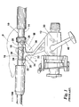
- Figure 2 contains a side perspective view of an inventive spinning reel frame 50 from the palm side of a preferred reel foot / stem arrangement.
- Figure 3 is a side plan view of the inventive reel foot / stem arrangement.
- a conventional fishing rod 10 is shown with a conventional under-the-rod type spinning reel 12 mounted thereon.
- the fishing rod 10 has an elongate body 14 that has a mounting region at 16 which defines a seating surface 18 for the elongate mounting foot 20 of the fishing reel 12 .
- the forward portion 22 of the mounting foot 20 seats in a receptacle 24 defined on the fishing rod 10 .
- the rear portion 26 of the mounting foot 20 is maintained against the seating surface 18 by a locking ring 28 that is slidable lengthwise on the fishing rod 10 between (a) a release position wherein the fishing reel 12 can be selectively placed in the operative position of Figure 1 and separated from the fishing rod 10 and (b) a locking position, as shown in Figure 1 , wherein the mounting foot 20 is captive in fixed position against the rod surface 18 .
- This mounting arrangement is common to "under-the-rod" type reels, such as spinning reels, which are well known in the art.
- the mounting foot 20 is connected to the body 30 of the fishing reel 12 through a depending mounting stem 32 , which conventionally defines two regions 34 and 36 of equal extent fore and aft of the mounting stem. These regions accommodate the fingers of the user's hand when the mechanism is in use.
- a right-handed user as illustrated in Figure 1 , the palm P of the right hand is placed against the upper rod surface 38 .
- the user's index finger I and middle finger M are curled underneath the rod 10 to straddle the mounting stem 32 , and draw the rod surface 38 into the palm P . This position is maintained both when casting and retrieving the fishing line, the latter being accomplished by rotating the reel's crank handle 40 using the non-gripping (e.g., left) hand.
- Figure 1 pictures the traditional foot 20 / stem 32 arrangement, wherein the stem 32 bisects the foot 20 .
- the mounting foot 20 , mounting stem 32 , and reel body 30 are made from a hard material, such as metal, plastic, or a composite.
- the center of gravity of the combined rod 10 and reel 12 combination is somewhere ahead of the user's hand in the direction of the rod tip 100 (not shown).
- a spinning reel mounting device 200 wherein the reel stem 220 is asymmetrically joined to a reel foot 210 .
- a spinning style fishing reel 250 is shown, which reel 250 is of the type suitable for use with the present invention.
- the reel 250 consists of a fixed housing 260 with an integral mounting stem 220 with a foot 210 thereon suitable for attachment to a conventional fishing rod 10 .
- a spool 270 is provided at the front of the reel 250 that holds a supply of fishing line.
- a rotor 280 is provided to effect wrapping of the line around the spool 270 during recall of the line.
- the rotor 280 has diametrically opposed bail ears 222 , 224 which rotate about a longitudinal, fore and aft axis of the reel 250 , i.e., an axis generally parallel to the central axis of the spool 270.
- This rotation is imparted by turning a conventional external crank handle 228 through a mechanism well known to those skilled in the art. (See, for example, the mechanisms disclosed in U.S. Letters Patent 5,143,318, 5,921,489, and, 5,350,131, the disclosures of which are incorporated herein by reference.)
- the bail ears 222 , 224 cooperatively define a support for a pivotable bail assembly 229 consisting of spaced bail arms 230 , 232 and a formed wire bail 234 connecting therebetween.
- a line guide 236 on the bail assembly 229 engages the line and wraps the line around the hub 238 of the spool 270 .
- the line guide 236 preferably has a fixed axial position with respect to the reel as it is operating, it is necessary to reciprocate/oscillate the spool 270 about the fore and aft reel axis to cause an even distribution of line on the spool 270 during retrieval.
- the mounting device 200 of the instant invention has the stem 220 joined to the foot 210 at a position toward the rear of the reel 250 , i.e., behind the longitudinal midpoint of the foot 210 , wherein the longitudinal midpoint is simply the midpoint of the foot 210 as measured between its forward and rearward tips.
- the center of gravity of the combined rod 10 and reel 250 combination similarly moves toward the rear of the rod 10 (i.e., away from the rod tip 100 ) and toward the user's hand.
- the instant invention has been pictured only as being arranged with the stem 220 located toward the rear of the foot 210 , those skilled in the art recognize that it could alternatively be placed ahead of the foot 210 centerline. However, that would tend to move the center of gravity of the rod and reel toward the tip of the rod which, in most applications, would not be particularly desirable. That being said, depending on the rod, this arrangement might be desirable where, for example, the rod had a heavy handle relative to the rest of the rod.
Landscapes
- Life Sciences & Earth Sciences (AREA)
- Environmental Sciences (AREA)
- Animal Husbandry (AREA)
- Biodiversity & Conservation Biology (AREA)
- Fishing Rods (AREA)
Abstract
According to the preferred embodiment of the instant invention, there is provided a fishing
reel, wherein the reel stem is connected to the reel foot at a point other than at its center. When the
point of connection is nearer the rear of the rod, the net effect is to move the overall center of gravity
of the rod/reel combination nearer the user's hand, i.e., toward the handle of the rod. Further, in the
preferred arrangement, when the reel stem asymmetrically engages the reel foot the user will tend to
put the stem between the index and middle fingers, thereby moving the hand grip position toward
the tip of the reel and nearer the location of the center of gravity.
Description
- The present invention relates to the general subject matter of fishing reels, and more particularly, to various arrangements of the reel foot and stem combination.
- As is well known to those in the art, in general operation a fisherman ties some sort of object (e.g., a fishing lure) to one end of a long continuous piece of fishing line, the other end of which is secured to a spindle or spool inside of the fishing reel. Between the lure and the spool, the line from the fishing reel spool is threaded through guide rings of generally increasing diameter along the length of a rod. The excess fishing line is wrapped about this same spool. In normal operation, the selected object and the line attached thereto are cast into the water, with line from within the reel being smoothly released from the reel so as to impede as little as possible the flight of the cast object. Then, the line is recalled back into the device through the use of a handle or crank that turns the spool from which the line was originally sourced, thereby winding it once again about the spool. Of course, in the preferred scenario a fish will be attached to the remote end of the line when it is so-recalled.
- The spinning reel portion of a rod and reel combination typically comprises: an elongate mounting foot; a reel body; and a reel stem (or "leg" as it is sometimes referred to in the argot of the trade) extending between the mounting foot and the reel body. Conventionally, the mounting foot and stem cooperatively form a T shape, wherein the stem bisects the foot along its longitudinal length. When it is installed on a rod, the mounting foot of the reel is placed in contact with a reel seat on the rod and removably secured thereto by any number of different means, e.g., a locking nut or ring is a popular choice. Examples of prior art rod seats may be found in U.S. Letters Patent 4,187,633, 4,860,484, 4,905,400, and 5,904,000, the disclosures of which are incorporated herein by reference.
- During the process of casting and retrieving the fishing line, the fisherman / fisherwoman will typically hold the rod and reel combination by placing his or her index and middle fingers beneath the rod on opposite sides of the reel stem and using the index and middle fingers to hold the fishing rod portion against the palm of the hand. This arrangement is comfortable for most users because, when the hand is so positioned, the index finger is in a position to secure the line during the rearward component of the casting motion and then to release it at some point during the forward (or throwing) motion component.
- Needless to say, the overall balance of the rod and reel combination can contribute to (or detract from) the user's casting motion, subsequent line retrieval, and overall enjoyment of the fishing experience. In most cases, the center of gravity of the combination is located somewhere in front of the user's normal hand position (i.e., between the user's hand and the tip of the rod). Of course, it is difficult to state with any specificity the location of the center of gravity, because of the enormous number of rod and reel combinations that are available to the end user, the location of the center of gravity generally depending on the relative weights of the rod and reel and the center of gravity of the rod alone. That being said, however, as a general rule the center of gravity in most cases is in front of the normal gripping position.
- The fact that the center of gravity of the rod/reel combination tends to be ahead of the user's gripping hand has a number of consequences for the user. First, and as is predicted by basic physics, as the center of gravity moves forward toward the tip of the rod, the user will find it increasingly more difficult to accelerate the rod tip during casting. Further, once the rod is placed into motion (as during a cast), the user will have to exert more force to stop it. Still further, as the center of gravity moves forward, the user will find it increasingly difficult to main the rod in a horizontal position, and will need to apply increasing restoring force to keep it level. Finally, to the extent that a rod is "tip heavy", the ability of users to"feel" their bait and fish strikes is reduced. This is because when the rod is tip heavy much of what a fisherman feels is the downward force of the rod tip so that the feel of the bait, bottom structure, and fish strikes is masked (and lessened) by the downward force of the fishing rod as it seeks to rotate about its point of support in the user's hand.
- All of this force, of course, is applied through the user's wrist and, if the balance of the combination is sufficiently loaded toward the forward end of the rod, the user's hand may tire prematurely, which is affect adversely the fishing experience. Clearly, it is desirable and advantageous to have the center of gravity near the user's hand and, in many cases, located within the span of the gripping hand.
- Of course, one obvious method of adjusting the location of the center of gravity of the rod and, thus, the combination is to modify its weight distribution by adding weight to the handle of the rod. Examples of this approach may be found in U.S. Letters Patent 5,535,539 and 5,355,611, the disclosures of which are incorporated herein by reference. However, adding weight to the rod in an attempt to change its balance has the adverse consequence of increasing the overall weight of the rod which, itself, may result in hand tiring.
- Further, some rods provide a plurality of positions at which the reel may be located. However, in those cases it is up the user to position the reel mounting foot against the reel seat so as to balance the resulting combination as nearly as possible. Most users will not want to devote the time required to perform this task, as it could require balancing the combination via trial-and-error.
- Thus, what is needed is a way of relocating the center of gravity of rod / reel combination to a position nearer the user's holding hand. Further, this method must not be highly dependent upon the weight characteristics of the individual components.
- Heretofore, as is well known in the fishing arts, there has been a need for an invention to address and solve the above-described problems. Accordingly, it should now be recognized, as was recognized by the present inventor, that there exists, and has existed for some time, a very real need for a device that would address and solve the above-described problems.
- Before proceeding to a description of the present invention, however, it should be noted and remembered that the description of the invention which follows, together with the accompanying drawings, should not be construed as limiting the invention to the examples (or preferred embodiments) shown and described. This is so because those skilled in the art to which the invention pertains will be able to devise other forms of this invention within the ambit of the appended claims.
- According to a preferred aspect of the instant invention, there is provided a reel foot / stem combination that are joined together in an asymmetric arrangement. In more particular, in the preferred embodiment a fishing reel is provided, wherein the reel stem is connected to the reel foot at a point other than at its center. When the point of connection is nearer the rear of the rod, the net effect is to move the overall center of gravity of the rod/reel combination nearer the user's hand. (The directions "forward" and "rearward" are defined herein with respect to the rod tip and rod handle, respectively). Further, in the preferred arrangement, when the reel stem asymmetrically engages the reel foot the user will tend to put the stem between the middle fingers, thereby moving the hand toward the tip of the reel and nearer the location of the center of gravity.
- The foregoing has outlined in broad terms the more important features of the invention disclosed herein so that the detailed description that follows may be more clearly understood, and so that the contribution of the instant inventor to the art may be better appreciated. The instant invention is not to be limited in its application to the details of the construction and to the arrangements of the components set forth in the following description or illustrated in the drawings. Rather, the invention is capable of other embodiments and of being practiced and carried out in various other ways not specifically enumerated herein. Additionally, the disclosure that follows is intended to cover all alternatives, modifications and equivalents as may be included within the spirit and scope of the invention as defined by the appended claims. Further, it should be understood that the phraseology and terminology employed herein are for the purpose of description and should not be regarded as limiting, unless the specification specifically so limits the invention. Further objects, features, and advantages of the present invention will be apparent upon examining the accompanying drawings and upon reading the following description of the preferred embodiments.
- Figure 1 provides an elevational side view of a conventional spinning reel removably secured beneath a
fishing rod 10. - Figure 2 contains a side perspective view of an inventive spinning reel frame 50 from the palm side of a preferred reel foot / stem arrangement.
- Figure 3 is a side plan view of the inventive reel foot / stem arrangement.
- In Figure 1, a
conventional fishing rod 10 is shown with a conventional under-the-rodtype spinning reel 12 mounted thereon. Thefishing rod 10 has anelongate body 14 that has a mounting region at 16 which defines aseating surface 18 for theelongate mounting foot 20 of thefishing reel 12. Theforward portion 22 of the mountingfoot 20 seats in areceptacle 24 defined on thefishing rod 10. Therear portion 26 of themounting foot 20 is maintained against theseating surface 18 by alocking ring 28 that is slidable lengthwise on thefishing rod 10 between (a) a release position wherein thefishing reel 12 can be selectively placed in the operative position of Figure 1 and separated from thefishing rod 10 and (b) a locking position, as shown in Figure 1, wherein the mountingfoot 20 is captive in fixed position against therod surface 18. This mounting arrangement is common to "under-the-rod" type reels, such as spinning reels, which are well known in the art. - The mounting
foot 20 is connected to thebody 30 of thefishing reel 12 through a dependingmounting stem 32, which conventionally defines tworegions upper rod surface 38. The user's index finger I and middle finger M are curled underneath therod 10 to straddle themounting stem 32, and draw therod surface 38 into the palm P. This position is maintained both when casting and retrieving the fishing line, the latter being accomplished by rotating the reel's crank handle 40 using the non-gripping (e.g., left) hand. Figure 1 pictures thetraditional foot 20 /stem 32 arrangement, wherein thestem 32 bisects thefoot 20. - Typically, the mounting
foot 20, mountingstem 32, and reelbody 30 are made from a hard material, such as metal, plastic, or a composite. In the a conventional configuration such as this, the center of gravity of the combinedrod 10 and reel 12 combination is somewhere ahead of the user's hand in the direction of the rod tip 100 (not shown). - According to a preferred aspect of the instant invention and as is pictured in Figures 2 and 3, there is provided a spinning
reel mounting device 200, wherein thereel stem 220 is asymmetrically joined to areel foot 210. In these figures, a spinningstyle fishing reel 250 is shown, whichreel 250 is of the type suitable for use with the present invention. Thereel 250 consists of a fixedhousing 260 with an integral mounting stem 220 with afoot 210 thereon suitable for attachment to aconventional fishing rod 10. - As is customary for this general sort of reel, a
spool 270 is provided at the front of thereel 250 that holds a supply of fishing line. To effect wrapping of the line around thespool 270 during recall of the line, arotor 280 is provided. Therotor 280 has diametrically opposedbail ears reel 250, i.e., an axis generally parallel to the central axis of thespool 270. This rotation is imparted by turning a conventional external crankhandle 228 through a mechanism well known to those skilled in the art. (See, for example, the mechanisms disclosed in U.S. Letters Patent 5,143,318, 5,921,489, and, 5,350,131, the disclosures of which are incorporated herein by reference.) - The
bail ears pivotable bail assembly 229 consisting of spacedbail arms wire bail 234 connecting therebetween. As therotor 280 is operated, aline guide 236 on thebail assembly 229 engages the line and wraps the line around thehub 238 of thespool 270. Because theline guide 236 preferably has a fixed axial position with respect to the reel as it is operating, it is necessary to reciprocate/oscillate thespool 270 about the fore and aft reel axis to cause an even distribution of line on thespool 270 during retrieval. - The mounting
device 200 of the instant invention has thestem 220 joined to thefoot 210 at a position toward the rear of thereel 250, i.e., behind the longitudinal midpoint of thefoot 210, wherein the longitudinal midpoint is simply the midpoint of thefoot 210 as measured between its forward and rearward tips. Of course, as the jointing point between thestem 220 andfoot 210 is moved toward the rear of thefoot 210, the center of gravity of the combinedrod 10 and reel 250 combination similarly moves toward the rear of the rod 10 (i.e., away from the rod tip 100) and toward the user's hand. Additionally, most users will find it more comfortable to place the asymmetrically joinedstem 220 between the middle M and fourth fingers, rather than between the index I and middle M fingers, thus shifting the user's hold upward on therod 10 and nearer to the center of gravity. Finally, since most users prefer to keep the index finger I proximate to thespool 238 so that the line may be readily seized when casting, that factor additionally encourages the user to position thestem 220 of the instantreel mounting device 200 between the middle and fourth fingers. - Of course, there are practical limitations to how far rearward the point of intersection of these two elements can be moved because, for example, at least some of the
foot 210 must be available for mounting thereel 250 on therod 10. Additionally, ergometric design considerations should be taken into account and it may be that, depending on the particular rod and reel involved, that attachment positions short of the most rearward could provide a better feel for the end user. - Finally, although the instant invention has been pictured only as being arranged with the
stem 220 located toward the rear of thefoot 210, those skilled in the art recognize that it could alternatively be placed ahead of thefoot 210 centerline. However, that would tend to move the center of gravity of the rod and reel toward the tip of the rod which, in most applications, would not be particularly desirable. That being said, depending on the rod, this arrangement might be desirable where, for example, the rod had a heavy handle relative to the rest of the rod. - While the inventive device has been described and illustrated herein by reference to certain preferred embodiments in relation to the drawings attached hereto, various changes and further modifications, apart from those shown or suggested herein, may be made therein by those skilled in the art, without departing from the spirit of the inventive concept, the scope of which is to be determined by the following claims.
Claims (6)
- A reel mounting device, comprising an under-the-rod type fishing reel including a foot structure for securing said fishing reel on a fishing rod, said foot structure having a longitudinal midpoint, a reel body, and a reel stem extending between said foot structure and said reel body, wherein said reel stem is joined to said foot.structure at a point substantially different from said longitudinal midpoint.
- A rod mounting device according to Claim 1, wherein said foot structure has a forward tip and a rearward tip, and wherein said reel stem is joined to said foot structure at a point nearer to said reward tip than to said forward tip.
- A reel mounting device, comprising:(a) a fishing reel body having an upper surface;(b) a foot structure for securing said fishing reel body to a fishing rod seat, said foot structure having a longitudinal midpoint; and,(c) a reel stem having an upper terminus and a lower terminus, said lower terminus joined to said fishing reel upper surface, and said upper terminus joined to said foot structure at a point different from said longitudinal midpoint.
- A real mounting device according to Claim 3, wherein said foot structure has a forward terminus and a rearward terminus, and wherein said reel stem is joined to said foot structure at a point nearer said rearward terminus than to said forward terminus.
(b) a reel stem having an upper end and a lower end, said joined to said - An apparatus for fishing, comprising:(a) a rod, said rod having a reel seat;(b) a housing;(c) a line carrying spool,(d) a rotor mounted for rotation relative to said housing and for directing fishing line onto said spool;(e) a rotatable crank handle for operating said rotor; and,(f) a reel mounting device for mounting said fishing reel on said rod, said real mounting device having(1) a mounting foot for engaging said reel seat of said rod, said mounting foot having a longitudinal midpoint, and,(2) a reel stem having a lower terminus and an upper terminus, said lower terminus joined to said housing, and, said upper terminus joined to said mounting foot at a point different from said longitudinal midpoint.
- A fishing reel according to Claim 5, wherein said mounting foot has a rearward end, and wherein said reel stem is joined to said mounting foot at a point between said longitudinal midpoint and said rearward end.
Applications Claiming Priority (2)
| Application Number | Priority Date | Filing Date | Title |
|---|---|---|---|
| US46920599A | 1999-12-21 | 1999-12-21 | |
| US469205 | 1999-12-21 |
Publications (1)
| Publication Number | Publication Date |
|---|---|
| EP1110449A1 true EP1110449A1 (en) | 2001-06-27 |
Family
ID=23862885
Family Applications (1)
| Application Number | Title | Priority Date | Filing Date |
|---|---|---|---|
| EP00305947A Withdrawn EP1110449A1 (en) | 1999-12-21 | 2000-07-13 | Asymmetrically joined spinning reel foot and stem |
Country Status (5)
| Country | Link |
|---|---|
| EP (1) | EP1110449A1 (en) |
| JP (1) | JP2001178326A (en) |
| KR (1) | KR20010067198A (en) |
| CN (1) | CN1305703A (en) |
| NO (1) | NO20005096L (en) |
Cited By (3)
| Publication number | Priority date | Publication date | Assignee | Title |
|---|---|---|---|---|
| US7670125B2 (en) | 2004-02-10 | 2010-03-02 | Foboha Gmbh Formenbau | Device for injection moulding and assembling plastic parts |
| EP2559542A1 (en) | 2006-02-23 | 2013-02-20 | Foboha Gmbh Formenbau | Multi-component injection molding device |
| WO2018085907A1 (en) * | 2016-11-10 | 2018-05-17 | Henkels Junior Lourival Agenor | Reel with inclined angle to the first carrier ring |
Citations (14)
| Publication number | Priority date | Publication date | Assignee | Title |
|---|---|---|---|---|
| CH258217A (en) * | 1945-10-05 | 1948-11-30 | Huillet Jean | Reel for casting fishing. |
| US4187633A (en) | 1978-02-07 | 1980-02-12 | Fuji Kogyo Co., Ltd. | Reel seat for fishing rods |
| US4753398A (en) * | 1984-11-02 | 1988-06-28 | Shimano Industrial Company Limited | Mounting leg for a fishing reel |
| US4830306A (en) * | 1986-08-25 | 1989-05-16 | Ryobi Ltd. | Fishing reel leg with soft cover |
| US4860484A (en) | 1986-07-14 | 1989-08-29 | Green Milton J | Reel seat structures for fishing rods |
| US4905399A (en) * | 1989-01-26 | 1990-03-06 | David Hopps | Fishing rod and reel |
| US4905400A (en) | 1984-05-15 | 1990-03-06 | Brackett John E | Contoured spinning rod and handle assembly |
| US5143318A (en) | 1990-06-18 | 1992-09-01 | Zebco Corporation | Spool oscillation structure for fishing reel |
| US5350131A (en) | 1990-11-10 | 1994-09-27 | D.A.M. Deutsche Angelgerate Manufaktur Hellmuth Kuntze Gmbh & Co. Kg | Fishing reels with a spool receiving the fishing line |
| US5355611A (en) | 1993-08-16 | 1994-10-18 | Fishing Designs, Inc. | Balancer for fishing rods |
| US5535539A (en) | 1994-09-21 | 1996-07-16 | Vetre; Bruce A. | Fishing rod handle with extension |
| EP0819379A1 (en) * | 1996-07-18 | 1998-01-21 | Seiko Instruments Inc. | Reel mounting structure |
| US5904000A (en) | 1996-05-16 | 1999-05-18 | Fuji Kogyo Co., Ltd. | Reel seat for use on fishing rods |
| US5921489A (en) | 1996-09-09 | 1999-07-13 | Daiwa Seiko, Inc. | Oscillate mechanism for a fishing spinning reel |
Family Cites Families (1)
| Publication number | Priority date | Publication date | Assignee | Title |
|---|---|---|---|---|
| KR970003858U (en) * | 1995-07-20 | 1997-02-19 | 유병돈 | Reel seat structure of spinning reel for fishing rod |
-
2000
- 2000-07-13 EP EP00305947A patent/EP1110449A1/en not_active Withdrawn
- 2000-08-11 JP JP2000243645A patent/JP2001178326A/en active Pending
- 2000-08-21 CN CN00124050A patent/CN1305703A/en active Pending
- 2000-09-20 KR KR1020000055083A patent/KR20010067198A/en not_active Abandoned
- 2000-10-10 NO NO20005096A patent/NO20005096L/en not_active Application Discontinuation
Patent Citations (14)
| Publication number | Priority date | Publication date | Assignee | Title |
|---|---|---|---|---|
| CH258217A (en) * | 1945-10-05 | 1948-11-30 | Huillet Jean | Reel for casting fishing. |
| US4187633A (en) | 1978-02-07 | 1980-02-12 | Fuji Kogyo Co., Ltd. | Reel seat for fishing rods |
| US4905400A (en) | 1984-05-15 | 1990-03-06 | Brackett John E | Contoured spinning rod and handle assembly |
| US4753398A (en) * | 1984-11-02 | 1988-06-28 | Shimano Industrial Company Limited | Mounting leg for a fishing reel |
| US4860484A (en) | 1986-07-14 | 1989-08-29 | Green Milton J | Reel seat structures for fishing rods |
| US4830306A (en) * | 1986-08-25 | 1989-05-16 | Ryobi Ltd. | Fishing reel leg with soft cover |
| US4905399A (en) * | 1989-01-26 | 1990-03-06 | David Hopps | Fishing rod and reel |
| US5143318A (en) | 1990-06-18 | 1992-09-01 | Zebco Corporation | Spool oscillation structure for fishing reel |
| US5350131A (en) | 1990-11-10 | 1994-09-27 | D.A.M. Deutsche Angelgerate Manufaktur Hellmuth Kuntze Gmbh & Co. Kg | Fishing reels with a spool receiving the fishing line |
| US5355611A (en) | 1993-08-16 | 1994-10-18 | Fishing Designs, Inc. | Balancer for fishing rods |
| US5535539A (en) | 1994-09-21 | 1996-07-16 | Vetre; Bruce A. | Fishing rod handle with extension |
| US5904000A (en) | 1996-05-16 | 1999-05-18 | Fuji Kogyo Co., Ltd. | Reel seat for use on fishing rods |
| EP0819379A1 (en) * | 1996-07-18 | 1998-01-21 | Seiko Instruments Inc. | Reel mounting structure |
| US5921489A (en) | 1996-09-09 | 1999-07-13 | Daiwa Seiko, Inc. | Oscillate mechanism for a fishing spinning reel |
Cited By (4)
| Publication number | Priority date | Publication date | Assignee | Title |
|---|---|---|---|---|
| US7670125B2 (en) | 2004-02-10 | 2010-03-02 | Foboha Gmbh Formenbau | Device for injection moulding and assembling plastic parts |
| US8470228B2 (en) | 2004-02-10 | 2013-06-25 | Foboha Gmbh Formenbau | Method and a device for injection moulding and assembling plastic parts |
| EP2559542A1 (en) | 2006-02-23 | 2013-02-20 | Foboha Gmbh Formenbau | Multi-component injection molding device |
| WO2018085907A1 (en) * | 2016-11-10 | 2018-05-17 | Henkels Junior Lourival Agenor | Reel with inclined angle to the first carrier ring |
Also Published As
| Publication number | Publication date |
|---|---|
| NO20005096D0 (en) | 2000-10-10 |
| CN1305703A (en) | 2001-08-01 |
| NO20005096L (en) | 2001-06-22 |
| KR20010067198A (en) | 2001-07-12 |
| JP2001178326A (en) | 2001-07-03 |
Similar Documents
| Publication | Publication Date | Title |
|---|---|---|
| US4651461A (en) | Fishing rod handle | |
| US2823483A (en) | Combination fish pole and slingshot as a fishing device | |
| US7089699B2 (en) | Fly fishing rod having a detachable reel seat and waist holder therefore | |
| US5363586A (en) | Dual-grip fishing rod handle | |
| US20110005120A1 (en) | Bow Fishing Rod | |
| US5992079A (en) | Wristsaver fishing rod handle and system | |
| US7086195B2 (en) | Fly fishing rod having a detachable reel seat and waist holder therefore | |
| US4654996A (en) | Casting rod handle with pistol grip and butt extension | |
| EP1106063A1 (en) | Asymmetric oscillation mechanism for a spinning reel | |
| US4261128A (en) | Fishing rod holder | |
| US7784214B2 (en) | Method and device for selectively positioning a fishing reel upon a rod | |
| AU2007284070A1 (en) | Fishing casting device | |
| US20060101702A1 (en) | Bait-casting rod handle | |
| KR20010067198A (en) | Asymmetrically joined spinning reel foot and stem | |
| US4429481A (en) | Spin-casting rod with lure jerking assembly | |
| US2753130A (en) | Line fishing implement | |
| WO2017005593A1 (en) | A device for use in sea fishing | |
| US3060617A (en) | Fishing rod | |
| KR20100134316A (en) | Asymmetrically Coupled Spinning Reels and Stems | |
| CA3022746A1 (en) | Ergonomic spincast reel | |
| US20060086033A1 (en) | Fishing rod handle | |
| KR20080111763A (en) | Spinning Reel and Stem | |
| US3653141A (en) | Fishing reel mount | |
| US11076587B2 (en) | Systems, methods, and apparatuses for implementing a center-pin housing-free reel with variable resistance braking and a casting pivot upon a transaxial plane | |
| JP2004194565A (en) | Fishing reel handle device |
Legal Events
| Date | Code | Title | Description |
|---|---|---|---|
| PUAI | Public reference made under article 153(3) epc to a published international application that has entered the european phase |
Free format text: ORIGINAL CODE: 0009012 |
|
| AK | Designated contracting states |
Kind code of ref document: A1 Designated state(s): AT BE CH CY DE DK ES FI FR GB GR IE IT LI LU MC NL PT SE |
|
| AX | Request for extension of the european patent |
Free format text: AL;LT;LV;MK;RO;SI |
|
| AKX | Designation fees paid | ||
| REG | Reference to a national code |
Ref country code: DE Ref legal event code: 8566 |
|
| STAA | Information on the status of an ep patent application or granted ep patent |
Free format text: STATUS: THE APPLICATION IS DEEMED TO BE WITHDRAWN |
|
| 18D | Application deemed to be withdrawn |
Effective date: 20011228 |