EP1109378A2 - Device and method for monitoring a shock experienced by a mobile telephone - Google Patents
Device and method for monitoring a shock experienced by a mobile telephone Download PDFInfo
- Publication number
- EP1109378A2 EP1109378A2 EP00310486A EP00310486A EP1109378A2 EP 1109378 A2 EP1109378 A2 EP 1109378A2 EP 00310486 A EP00310486 A EP 00310486A EP 00310486 A EP00310486 A EP 00310486A EP 1109378 A2 EP1109378 A2 EP 1109378A2
- Authority
- EP
- European Patent Office
- Prior art keywords
- signal
- speaker
- shock
- mobile phone
- monitoring
- Prior art date
- Legal status (The legal status is an assumption and is not a legal conclusion. Google has not performed a legal analysis and makes no representation as to the accuracy of the status listed.)
- Withdrawn
Links
Images


Classifications
-
- H—ELECTRICITY
- H04—ELECTRIC COMMUNICATION TECHNIQUE
- H04W—WIRELESS COMMUNICATION NETWORKS
- H04W88/00—Devices specially adapted for wireless communication networks, e.g. terminals, base stations or access point devices
- H04W88/02—Terminal devices
-
- H—ELECTRICITY
- H04—ELECTRIC COMMUNICATION TECHNIQUE
- H04M—TELEPHONIC COMMUNICATION
- H04M1/00—Substation equipment, e.g. for use by subscribers
- H04M1/02—Constructional features of telephone sets
- H04M1/18—Telephone sets specially adapted for use in ships, mines, or other places exposed to adverse environment
-
- H—ELECTRICITY
- H04—ELECTRIC COMMUNICATION TECHNIQUE
- H04M—TELEPHONIC COMMUNICATION
- H04M1/00—Substation equipment, e.g. for use by subscribers
- H04M1/72—Mobile telephones; Cordless telephones, i.e. devices for establishing wireless links to base stations without route selection
- H04M1/724—User interfaces specially adapted for cordless or mobile telephones
Definitions
- This invention relates to mobile electronic apparatus such as a mobile telephone handset.
- the dynamic speaker provided as standard equipment in many items of mobile electronic apparatus such as mobile phones, is used as a transducer to sense the shock experienced by the phone. Movement of the speaker core by an external force will produce a signal that is recorded in the memory of the phone. This can be accessed during service to determine if the phone was subjected to excessive force which may negate the warranty.
- the shock signal from the speaker is filtered and compared to a predetermined threshold. Therefore only the data relating to substantial force are recorded.
- a sensor circuit 1 has its output connected to the microprocessor control unit 2 of a mobile phone.
- the analog signal from the sensor 1 is converted to a digital signal in the analog to digital converter 3 for storage in a random access memory 4 within the microprocessor control unit 2.
- Memory 4 maybe accessed by a service processor 5 through the use of service software designed for that purpose.
- the components of the sensor circuit 1 are shown in figure 2 and include a dynamic speaker 6 connected to a amplifier/filter circuit 7 and a comparator circuit 8.
- the amplifier/filter circuit 7 provides buffer impedance for the low impedance signal from the speaker 6 and if necessary may also provide amplification.
- Comparator circuit 8 receives a reference voltage V REF from the microprocessor control unit 2 which is compared to the signal from speaker 6. In this manner, an output threshold is set to limit the shock signals to those greater than a minimum value, as it is only the extremes of shock forces that it is desired to record.
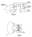
- the signal from speaker 6 may be processed in a variety of ways to achieve the monitoring purpose of this invention, a specific sensor processing circuit 1 is shown in figure 3 for the purpose of illustration. In general because of the significant voltages generated by the speaker 6 when it receives a significant physical shock, amplification will not normally be required.
- the signal from the speaker 6 is passed through an amplifier/filter circuit 7 which provides buffer impedance for the low impedance signal of speaker 6 and filters out environmental disturbances.
- Circuit 7 includes an amplifier 9 and a filter 10.
- a voltage reference V REF is set by microprocessor control unit 2, through a digital to analog converter 16 which facilitates alignment of the reference voltage during production.
- V REF is compared to the output signal V OUT of the amplifier/filter circuit 7 in comparator circuit 8, which includes an amplifier 17.
- Comparator circuit 8 is designed to generate a trigger pulse V TRIGGER when V OUT is greater than V REF . This requires significant peaks of voltage which indicate extraordinary shocks received by the mobile phone. As shown in figures 3 and 5, V TRIGGER will go to the positive supply voltage (+5V)of amplifer 17 and will be detected as an interrupt by microprocessor control unit 2 to initiate the storing of the value of V out .
- a unique feature of this invention is the use of the dynamic speaker of the mobile phone as a transducer to sense when the mobile phone is subjected to significant shock.
- a schematic of a typical speaker is shown in figure 4.
- speaker 6 is comprised of a cone 11 connected to a moveable core or diaphragm 12 which is mounted for movement within a wire coil or winding 13.
- the diaphragm 12 contains a permanent magnet 14 which, in normal use, is caused to move within the winding 13 in response to voice signals from a receiver in the mobile phone.
- the speaker 6 is also used as a transducer by reversing its operation. Violent movement of the mobile phone will jar the diaphragm 13 and cause the magnet 14 to move within winding 13.
- V SHOCK is processed by amplifier/filter 9 and comparator 10.
- the shock signal is processed to eliminate spikes of voltage which may be caused by environmental disturbances or by minimal jarring during normal use. Peak signals are stored in the random access memory 4.
- the service technician may access the random access memory through an access port and, using a tool designed for this purpose download the shock signal record for analysis. Warranty service may be refused if the record indicates a misuse of the mobile phone.
- This system may be used in other devices which employ dynamic speakers such as portable radios, cordless phones, beepers and the like.
Landscapes
- Engineering & Computer Science (AREA)
- Signal Processing (AREA)
- Computer Networks & Wireless Communication (AREA)
- Human Computer Interaction (AREA)
- Telephone Function (AREA)
- Alarm Systems (AREA)
- Burglar Alarm Systems (AREA)
- Selective Calling Equipment (AREA)
Abstract
Description
Claims (10)
- In apparatus containing a dynamic speaker, said speaker having a magnetized core and an input coil, a method of monitoring the shock to which the apparatus is subjected, comprising the steps of:providing an alternative connection to said speaker to provide an output for the voltage signal generated by movement of said magnetized core within said input coil when the apparatus is subject to shock,processing said signal to block the monitored signals which are below a predetermined minimum;converting said signal to a digital signal; andstoring said signal in a microprocessor for future reference.
- In apparatus containing a dynamic speaker, said speaker having a magnetized core and an input coil, a method of monitoring the shock to which the apparatus is subjected, as described in claim 1 further comprising the step of filtering said signal to isolate the shock signal from environmental disturbances.
- In a mobile phone containing a dynamic speaker, said speaker having a magnetized core and an input coil, said mobile phone containing a microprocessor, a method of monitoring the shock to which the apparatus is subjected comprising the steps of:providing an alternative connection to said speaker to provide an output for the voltage signal generated by movement of said magnetized core within said input coil, when said mobile phone is subject to shock,processing said signal to block the monitored signals which are below a predetermined minimum;converting said signal to a digital signal; andstoring said signal in said microprocessor for future reference.
- In a mobile phone containing a dynamic speaker, said speaker having a magnetized core and an input coil, said mobile phone containing a microprocessor, a method of monitoring the shock to which the apparatus is subjected, as described in claim 3, further comprising the step of filtering said signal to isolate the shock signal from environmental disturbances.
- In apparatus containing a dynamic speaker, said speaker having a magnetized core and an input coil, a device for monitoring the shock to which the apparatus is subjected comprising:an output connected to the speaker coil for obtaining the voltage signal generated by movement of said magnetized core within said input coil when the device is subject to shock,a processor connected to receive the filtered signal and to block the monitored signals which are below a predetermined minimum;a microprocessor connected to receive the processed signal, convert said signal to digital form and to store said signal in said microprocessor for future reference.
- In apparatus containing a dynamic speaker, said speaker having a magnetized core and an input coil, a device for monitoring the shock to which the apparatus is subjected, as described in claim 5, further comprising a filter connected to receive said signal and to isolate said signal from environmental disturbances.
- In a mobile phone which uses a dynamic speaker, said speaker having a magnetized core and an input coil, said mobile phone having microprocessor control, a device for monitoring the shock to which the apparatus is subjected comprising:an output connected to the speaker coil for obtaining the voltage signal generated by movement of said magnetized core within said input coil when the mobile phone is subject to shock;a processor connected to receive the filtered signal and to block those monitored signals that are below a predetermined minimum;said microprocessor control connected to receive the processed signal, convert said signal to digital form, and to store said signal in said microprocessor for future reference.
- In a mobile phone which uses a dynamic speaker, said speaker having a magnetized core and an input coil, said mobile phone having microprocessor control, a device for monitoring the shock to which the apparatus is subjected, as described in claim 7, further comprising a filter connected to receive said signal and to isolate said signal from environmental disturbances.
- Mobile electronic apparatus including a speaker (6) having a coil (13) and a magnetised element (14) to be moved by electrical energisation of the coil, characterised by a sensor circuit (1) responsive to relative movement of the coil (13) and the element (14) to sense mechanical shock suffered by the apparatus.
- Apparatus according to claim 9 and comprising a mobile telephone handset.
Applications Claiming Priority (2)
| Application Number | Priority Date | Filing Date | Title |
|---|---|---|---|
| US09/465,102 US6584198B1 (en) | 1999-12-16 | 1999-12-16 | Device and method for monitoring shock |
| US465102 | 1999-12-16 |
Publications (2)
| Publication Number | Publication Date |
|---|---|
| EP1109378A2 true EP1109378A2 (en) | 2001-06-20 |
| EP1109378A3 EP1109378A3 (en) | 2002-08-21 |
Family
ID=23846498
Family Applications (1)
| Application Number | Title | Priority Date | Filing Date |
|---|---|---|---|
| EP00310486A Withdrawn EP1109378A3 (en) | 1999-12-16 | 2000-11-27 | Device and method for monitoring a shock experienced by a mobile telephone |
Country Status (2)
| Country | Link |
|---|---|
| US (1) | US6584198B1 (en) |
| EP (1) | EP1109378A3 (en) |
Cited By (5)
| Publication number | Priority date | Publication date | Assignee | Title |
|---|---|---|---|---|
| WO2002065141A1 (en) * | 2001-02-15 | 2002-08-22 | Matsushita Electric Industrial Co., Ltd. | Electronic device and method for sensing shock to the device |
| WO2003081879A1 (en) * | 2002-03-26 | 2003-10-02 | Nokia Oyj | User interface for a portable telecommunication device |
| EP1474694A1 (en) * | 2002-02-12 | 2004-11-10 | Nokia Corporation | Acceleration sensor |
| WO2005071932A1 (en) * | 2004-01-22 | 2005-08-04 | Siemens Aktiengesellschaft | Mobile telephone |
| EP2263533A1 (en) | 2009-06-18 | 2010-12-22 | Deutsche Telekom AG | Enhancing security and emergency functionalities in mobile phones based on detection of physical shocks |
Families Citing this family (1)
| Publication number | Priority date | Publication date | Assignee | Title |
|---|---|---|---|---|
| US20060100887A1 (en) * | 2004-11-09 | 2006-05-11 | Erickson David E | Apparatus, system, and method for a motion based business decision |
Family Cites Families (6)
| Publication number | Priority date | Publication date | Assignee | Title |
|---|---|---|---|---|
| JPH07113551B2 (en) * | 1986-07-21 | 1995-12-06 | ティーディーケイ株式会社 | Tilt sensor |
| WO1991011723A1 (en) * | 1990-01-31 | 1991-08-08 | Sumitomo Electric Industries, Ltd. | Device for measuring acceleration and the like |
| US5742666A (en) * | 1994-10-05 | 1998-04-21 | Tele Digital Development, Inc. | Emergency mobile telephone |
| GB2334412A (en) * | 1998-02-13 | 1999-08-18 | Nokia Mobile Phones Ltd | Mobile telephone with emergency responsive mode |
| JPH11296765A (en) * | 1998-04-09 | 1999-10-29 | Kokusai Electric Co Ltd | Portable electronic devices |
| US6480699B1 (en) * | 1998-08-28 | 2002-11-12 | Woodtoga Holdings Company | Stand-alone device for transmitting a wireless signal containing data from a memory or a sensor |
-
1999
- 1999-12-16 US US09/465,102 patent/US6584198B1/en not_active Expired - Lifetime
-
2000
- 2000-11-27 EP EP00310486A patent/EP1109378A3/en not_active Withdrawn
Cited By (8)
| Publication number | Priority date | Publication date | Assignee | Title |
|---|---|---|---|---|
| WO2002065141A1 (en) * | 2001-02-15 | 2002-08-22 | Matsushita Electric Industrial Co., Ltd. | Electronic device and method for sensing shock to the device |
| US6864790B2 (en) | 2001-02-15 | 2005-03-08 | Matsushita Electric Industrial Co., Ltd. | Electronic apparatus and method of detecting shock given to the electronic apparatus |
| EP1474694A1 (en) * | 2002-02-12 | 2004-11-10 | Nokia Corporation | Acceleration sensor |
| US7350424B2 (en) | 2002-02-12 | 2008-04-01 | Nokia Corporation | Acceleration sensor |
| WO2003081879A1 (en) * | 2002-03-26 | 2003-10-02 | Nokia Oyj | User interface for a portable telecommunication device |
| US7593748B2 (en) | 2002-03-26 | 2009-09-22 | Panu Korhonen | User interface for a portable telecommunication device |
| WO2005071932A1 (en) * | 2004-01-22 | 2005-08-04 | Siemens Aktiengesellschaft | Mobile telephone |
| EP2263533A1 (en) | 2009-06-18 | 2010-12-22 | Deutsche Telekom AG | Enhancing security and emergency functionalities in mobile phones based on detection of physical shocks |
Also Published As
| Publication number | Publication date |
|---|---|
| EP1109378A3 (en) | 2002-08-21 |
| US6584198B1 (en) | 2003-06-24 |
Similar Documents
| Publication | Publication Date | Title |
|---|---|---|
| US5506891A (en) | Method and apparatus for detecting the connection status of an extension phone connected to a voice/fax/data modem | |
| US20080095391A1 (en) | Magnetic Sensor for a Transducer | |
| WO1998024215A1 (en) | Battery pack with audio coil | |
| KR920003191A (en) | Digital Signal Transceiver System, Digital Voice Signal Processing Circuit and Signal Conversion Circuit | |
| CA2760220C (en) | Apparatus, systems and methods for controlling an electronic device using an accessory | |
| US9258407B2 (en) | Portable electronic device having plurality of speakers and microphones | |
| CA2523931C (en) | Detection device | |
| KR20110040359A (en) | Earphone Recognition Circuit Device in Portable Terminal | |
| US6584198B1 (en) | Device and method for monitoring shock | |
| CN111601218B (en) | Audio playing switching method, Bluetooth loudspeaker box and Bluetooth audio playing device | |
| AU2004214555B2 (en) | Hearing aid with magnetic-field-controlled switch and corresponding method for operating a hearing aid | |
| CN105872909B (en) | A kind of method and device for realizing Audio Signal Processing | |
| US7593748B2 (en) | User interface for a portable telecommunication device | |
| US6825788B2 (en) | Analog-to-digital and digital-to-analog converter with standby output signal | |
| JP2019138778A (en) | Recording device and recording method | |
| JP2776783B2 (en) | Moving state detection circuit | |
| US7110892B2 (en) | Apparatus and method for determining strength of impact when closing a folder-type terminal | |
| US12333079B2 (en) | Surface audio device with haptic or audio feedback | |
| CN105681589A (en) | Incoming call prompt method and terminal | |
| EP1695592B1 (en) | Integrated circuit for hearing aids including a magnetic field sensor | |
| KR100222901B1 (en) | Audio signal input sensitivity automatic control circuit of monitor | |
| US20050185772A1 (en) | [digital audio recording apparatus providing call logging function] | |
| US5535272A (en) | Sensor circuit for a telephone line | |
| CN107743181A (en) | A kind of method and apparatus of Intelligent treatment incoming call | |
| CN218384495U (en) | Speech recognition equipment and vehicle |
Legal Events
| Date | Code | Title | Description |
|---|---|---|---|
| PUAI | Public reference made under article 153(3) epc to a published international application that has entered the european phase |
Free format text: ORIGINAL CODE: 0009012 |
|
| AK | Designated contracting states |
Kind code of ref document: A2 Designated state(s): AT BE CH CY DE DK ES FI FR GB GR IE IT LI LU MC NL PT SE TR |
|
| AX | Request for extension of the european patent |
Free format text: AL;LT;LV;MK;RO;SI |
|
| RAP1 | Party data changed (applicant data changed or rights of an application transferred) |
Owner name: NOKIA CORPORATION |
|
| PUAL | Search report despatched |
Free format text: ORIGINAL CODE: 0009013 |
|
| AK | Designated contracting states |
Kind code of ref document: A3 Designated state(s): AT BE CH CY DE DK ES FI FR GB GR IE IT LI LU MC NL PT SE TR |
|
| AX | Request for extension of the european patent |
Free format text: AL;LT;LV;MK;RO;SI |
|
| RIC1 | Information provided on ipc code assigned before grant |
Free format text: 7H 04M 1/18 A, 7H 04Q 7/32 B, 7G 01M 7/08 B, 7G 01P 15/11 B, 7H 04M 1/725 B |
|
| AKX | Designation fees paid | ||
| REG | Reference to a national code |
Ref country code: DE Ref legal event code: 8566 |
|
| STAA | Information on the status of an ep patent application or granted ep patent |
Free format text: STATUS: THE APPLICATION IS DEEMED TO BE WITHDRAWN |
|
| 18D | Application deemed to be withdrawn |
Effective date: 20030222 |