EP1109255A1 - An insulation-displacement terminal fitting and a production method therefor - Google Patents
An insulation-displacement terminal fitting and a production method therefor Download PDFInfo
- Publication number
- EP1109255A1 EP1109255A1 EP00127220A EP00127220A EP1109255A1 EP 1109255 A1 EP1109255 A1 EP 1109255A1 EP 00127220 A EP00127220 A EP 00127220A EP 00127220 A EP00127220 A EP 00127220A EP 1109255 A1 EP1109255 A1 EP 1109255A1
- Authority
- EP
- European Patent Office
- Prior art keywords
- blades
- wire
- cutting edges
- terminal fitting
- insulation displacement
- Prior art date
- Legal status (The legal status is an assumption and is not a legal conclusion. Google has not performed a legal analysis and makes no representation as to the accuracy of the status listed.)
- Granted
Links
- 238000006073 displacement reaction Methods 0.000 title claims description 41
- 238000004519 manufacturing process Methods 0.000 title claims description 9
- 238000005520 cutting process Methods 0.000 claims abstract description 110
- 239000011248 coating agent Substances 0.000 claims abstract description 44
- 238000000576 coating method Methods 0.000 claims abstract description 44
- 238000009413 insulation Methods 0.000 claims description 53
- 238000005452 bending Methods 0.000 claims description 14
- 239000002184 metal Substances 0.000 claims description 10
- 238000004049 embossing Methods 0.000 claims description 8
- 239000011347 resin Substances 0.000 abstract description 31
- 229920005989 resin Polymers 0.000 abstract description 31
- 238000007747 plating Methods 0.000 description 7
- 238000002788 crimping Methods 0.000 description 3
- 230000001419 dependent effect Effects 0.000 description 1
- 238000003780 insertion Methods 0.000 description 1
- 230000037431 insertion Effects 0.000 description 1
- 230000013011 mating Effects 0.000 description 1
Images


Classifications
-
- H—ELECTRICITY
- H01—ELECTRIC ELEMENTS
- H01R—ELECTRICALLY-CONDUCTIVE CONNECTIONS; STRUCTURAL ASSOCIATIONS OF A PLURALITY OF MUTUALLY-INSULATED ELECTRICAL CONNECTING ELEMENTS; COUPLING DEVICES; CURRENT COLLECTORS
- H01R4/00—Electrically-conductive connections between two or more conductive members in direct contact, i.e. touching one another; Means for effecting or maintaining such contact; Electrically-conductive connections having two or more spaced connecting locations for conductors and using contact members penetrating insulation
- H01R4/24—Connections using contact members penetrating or cutting insulation or cable strands
- H01R4/2416—Connections using contact members penetrating or cutting insulation or cable strands the contact members having insulation-cutting edges, e.g. of tuning fork type
- H01R4/2445—Connections using contact members penetrating or cutting insulation or cable strands the contact members having insulation-cutting edges, e.g. of tuning fork type the contact members having additional means acting on the insulation or the wire, e.g. additional insulation penetrating means, strain relief means or wire cutting knives
- H01R4/2466—Connections using contact members penetrating or cutting insulation or cable strands the contact members having insulation-cutting edges, e.g. of tuning fork type the contact members having additional means acting on the insulation or the wire, e.g. additional insulation penetrating means, strain relief means or wire cutting knives the contact members having a channel-shaped part, the opposite sidewalls of which comprise insulation-cutting means
Definitions
- the present invention relates to an insulation displacement terminal fitting and to a production method therefor.
- insulation displacement terminal fittings are formed by making cuts in a pair of side walls, bending cut portions inwardly substantially at right angles as blades, so that inwardly facing edges of a pair of blades act as cutting edges.
- Such insulation displacement terminal fittings are produced by applying plating to the outer surface of a planar conductive metal plate having a specified thickness, stamping out the metal plate in a specified shape having U-shaped slits in a part of wall portions, portions surrounded by the U-shaped slits becoming blades, bending the planar metal plate piece such that the wall portions stand and the blades extend inwardly to oppose cutting edges to each other.
- the opposed end surfaces of the cutting edges which are to be brought into contact with a core of a wire are fractured surfaces formed at the time of stamping-out, they are not protected by plating.
- plating has been generally applied to the fractured surfaces (opposed end surfaces). Such plating at a later stage means an increased number of operation steps, which results in higher production costs.
- insulation displacement terminal fittings which do not require plating at a later stage were developed.
- One example of such terminal fittings is disclosed in Japanese Unexamined Patent Publication No. 50(SHO)-114592.
- blade portions are formed by striking a pair of side walls to project inwardly by a press. Each blade portion is such that a V-shaped blade project from the corresponding side wall and an projecting edge of the blade serves as a contacting edge.
- the cutting edges of the V-shaped blades cut a resin coating of the wire and a thus exposed core comes into contact with the contacting edges.
- the projecting edges of the V-shaped blades which serve as contacting edges are left plated since they are formed by pushing the side walls plated before stamping-out inwardly. Thus, plating at a later stage is unnecessary.
- the blades formed by cutting portions of the side walls and bending the cut portions are "I-shaped" when viewed in a direction in which the wire is pushed in.
- an insulation displacement resistance resistance created during insulation displacement
- the blades formed by embossing are "V-shaped" when viewed in the direction in which the wire is pushed in. Accordingly, an insulation displacement resistance is disadvantageously large.
- an object of the present invention is to provide an insulation displacement terminal fitting and a production method therefor allowing to reduce an insulation displacement resistance of V-shaped blade portions.
- an insulation displacement terminal fitting in which:
- the blades are formed by bending portions of side walls of the insulation displacement terminal fitting inwardly.
- the blades are projecting substantially in V-shape when viewed in a wire pushing or insertion direction in which the wire is to be pushed.
- the contacting edges are continuously extending in the wire pushing direction from the projecting end of the two blades.
- an insulation displacement terminal fitting in which a wire is pushed in between one pair of blade portions in a direction normal to its longitudinal axis; each blade portion comprises two blades formed by bending portions of side walls of the insulation displacement terminal fitting inwardly and projecting in V-shape when viewed in a wire pushing direction in which the wire is pushed, and contacting edges extending in the wire pushing direction at the projecting end of the two blades; a resin coating of the wire pushed in between the two blade portions is cut by cutting edges of the blades so that a core of the wire is brought into contact with the contacting edges, wherein the cutting edges of the two blades forming a V-shape are so arranged as to come into contact with the resin coating at different timings while the wire is being pushed in.
- the two blades forming a V-shape do not simultaneously come into contact with the resin coating, but one blade first coming into contact therewith cuts it. Thus, a resistance during cutting can be small.
- the cutting edges of the two blades preferably forming substantially a V-shape are inclined from a corresponding side wall of the insulation displacement terminal fitting toward the corresponding contacting edge in such directions as to laterally guide the wire, and wherein the contacting timings of the cutting edges of the two blades with the insulation coating are differed by differing angles of inclination of the cutting edges.
- the cutting edges of the two blades forming a V-shape are inclined from the corresponding side wall toward the corresponding contacting edge in such directions as to guide the wire when viewed in the longitudinal direction of the wire, and the contacting timings of the cutting edges of the two blades with the resin coating are differed by differing angles of inclination of the cutting edges.
- the position of the wire can be corrected even if the wire is displaced with respect to widthwise direction.
- contacting timings of the cutting edges of the two blades with the insulation coating are differed by differing the position or height from the bottom at which the blades are positioned along the wire pushing direction.
- the cutting edges of the two blades forming a V-shape are so arranged at both of the one pair of blade portions as to come into contact with the resin coating at different timings while the wire is being pushed in.
- the preferably parallel cutting edges of the one pair of blade portions opposed to each other when viewed in the wire pushing direction come into contact with the resin coating at the same timing.
- the cutting edges of the one pair of blade portions substantially opposed to each are substantially parallel to each other.
- the wire is pressed in oblique directions by the respective cutting edges due to an elastic restoring force of the resin coating while the resin coating is being cut, and pushed along the longitudinal direction (e.g. forward) of the wire by additional pushing forces from the two cutting edges which act in oblique directions toward the longitudinal axis (e.g. a force acting in an obliquely forward direction to the right is given from the front cutting edge of the left blade portion and a force acting in an obliquely forward direction to the left is given from the front cutting edge of the right blade portion.
- production method for producing an insulation displacement terminal fitting according to the invention or an embodiment thereof having blade portions being formed with blades having cutting edges for cutting an insulation coating of a wire comprising the following steps:
- substantially triangular notches are formed in portions of the plate piece, which correspond to upper ends of the side walls after bending and where the blade portions are to be formed, wherein two inclined edges of each of the substantially triangular notches correspond to the cutting edges of the blades.
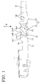
- FIGS. 1 to 3 left sides of FIGS. 1 to 3 are referred to as front; vertical direction is based on FIGS. 1 and 2; transverse direction is based on FIGS. 4 and 5; and right side of FIG. 3 is referred to as upper side.
- An insulation displacement terminal fitting according to this embodiment is produced preferably by stamping out or cutting a flat conductive metal plate 10 preferably having plating applied to its outer surface in a specified shape e.g. by a press, and applying embossing and bending to the stamped-out metal piece.
- a front end portion of the insulation displacement terminal fitting is an engaging portion 11 preferably in the form of a substantially rectangular tube, into which an unillustrated mating terminal fitting is insertable, and a rear end portion thereof is a wire connecting portion 12, which has an insulation displacement portion 13 preferably substantially at its front half and a crimping portion 14 preferably substantially at its rear half (rear end of the insulation displacement terminal fitting).
- the crimping portion 14 is comprised of a pair of crimping pieces 14A standing from a bottom wall 15 and crimped or bent or deformed or deformable into connection with a wire 16.
- the insulation displacement portion 13 is comprised of preferably two pairs of right and left blade portions 17R, 17L (collectively referred to as blade portions 17 in the following description unless either one of the blade portions is specified) which pairs are displaced in forward and backward directions. However, one or three or more blade portions 17 may be provided.
- the respective blade portions 17R, 17L are formed by embossing or bending or deforming side walls 18R, 18L (collectively referred to as side walls 18 in the following description unless either one of the side walls is specified), and are comprised of two blades 19RF, 19RR and two blades 19LF, 19LR (collectively referred to as blades 19 in the following description unless either one of the blades is specified) preferably projecting substantially in V-shape from the side walls 18 when viewed from above (in a direction in which the wire 16 is pushed in between the blade portions 17), and contacting edges 20R, 20L (collectively referred to as contacting edges 20 in the following description unless either one of the contacting edges is specified) vertically (wire pushing or inserting direction D) extending at a projecting end of the blades 19RF, 19RR and a projecting end of the 19LF, 19LR, respectively.
- Each pair of such blade portions 17R, 17L are preferably substantially opposed to each other while providing a specified spacing between the contacting edges 20R, 20L.
- the wire 16 is pushed in between the pair of the blade portions 17R, 17L in a direction arranged at an angle different from 0° or 180°, preferably substantially normal to a longitudinal axis from above.
- the pushed-in wire 16 has its insulation coating 16A, preferably its resin coating 16A cut or notched by cutting or notching edges 21RF, 21RR, 21LF, 21LR (collectively referred to as cutting edges 21 in the following description unless either one of the cutting edges is specified) of the blades 19, and the contacting edges 20R, 20L enter the cuts made in the resin coating 16A to come into contact with a core 16B at the substantially opposite sides.
- the blade portions 17 are formed by embossing portions of the flat metal plate piece (see FIG. 6), which become the side walls after bending, by means e.g. of a press.
- the side walls 18 are described here.
- Slits 22 are formed at folds 23F, 23C, 23R extending in the side walls 18 up to the bottom wall 15 in an area where the blade portions 17 are to be formed. The presence of the slits 22 prevents the bottom wall 15 from being distorted when the side walls 18 are embossed.
- a set of three transversely extending folds 23F, 23C, 23R are set at substantially regular intervals in forward and backward directions.
- These two sets of folds 23F, 23C, 23R are preferably symmetrically formed in the left and right side walls 18R, 18L with respect to a center longitudinal axis.
- Two sections between the front and rear folds 23F, 23R and the middle fold 23C become the blades 19 of the blade portions 17, and the middle folds 23C become the contacting edges 20 of the blade portions 17.
- triangular notches 24R, 24L are formed in portions of the plate piece, which become the upper ends of the side walls 18 after bending and where the blade portions 17 are to be formed. Two inclined edges of each of the notches 24R, 24L become the cutting edges 21 of the blades 19.
- the respective notches 24R, 24L are asymmetrical with respect to forward and backward directions as well as transverse direction.
- the front end of the front cutting edge 21 RF is located at the intersection of the side edge of the side wall 18R and the front fold 23F, and the rear end thereof is located at the middle fold 23C.
- the front end of the rear cutting edge 21 RR is located at the middle fold 23C (at the rear end of the front cutting edge 21RF), but the rear end thereof is located further backward from the intersection of the rear fold 23R with the side edge of the side wall 18R. Accordingly, an angle of inclination ⁇ of the front cutting edge 21 RF of the right notch 24R with respect to forward and backward directions is larger than an angle of inclination ⁇ of the rear cutting edge 21RR with respect thereto.
- the front cutting edge 21RF having a larger angle of inclination a comes into contact with the resin coating 16A of the wire before the rear cutting edge 21RR does.
- the front end of the front cutting edge 21LF is located more forward than the intersection of the side edge of the side wall 18L and the front fold 23F, and the rear end thereof is located at the middle fold 23C.
- the front end of the rear cutting edge 21LR is located at the middle fold 23C (at the rear end of the front cutting edge 21 LF), and the rear end thereof is located at the intersection of the rear fold 23R with the side edge of the side wall 18L. Accordingly, an angle of inclination ⁇ of the front cutting edge 21 LF with respect to forward and backward directions is smaller than an angle of inclination a of the rear cutting edge 21 LR with respect thereto.
- the rear cutting edge 21 LF having a larger angle of inclination ⁇ comes into contact with the resin coating 16A of the wire before the rear cutting edge 21 RR does.
- the right and left notches 24R, 24L are preferably symmetrical with respect to an intersection P (FIG. 6) of a widthwise center line of the bottom wall 15 and a line connecting the two middle folds 23.
- the angles of inclination of the front cutting edge 21 RF at the right side and of the rear cutting edge 21 LR at the left side are substantially the same, i.e. ⁇
- the angles of inclination of the rear cutting edge 21 RR at the right side and of the front cutting edge 21 LF at the left side are substantially the same, i.e. ⁇ .
- Jigs are or can be placed along the respective folds 23F, 23C, 23R of the side walls 18R, 18L in the development of the metal plate piece, and the blade portions 17R, 17L are formed by embossing e.g. by means of a press. Thereafter, the side walls 18R, 18L are bent at an angle different from 0° or 180°, preferably at a substantially right angle to the bottom wall 15 to form the insulation displacement portion 13.
- the cutting edges 21RF, 21LR having the larger angle of inclination ⁇ and the cutting edges 21 RR, 21 LF having the smaller angle of inclination ⁇ are located substantially on diagonal lines, respectively, as shown in FIG. 3. It should be noted that embossing is applied such that the angles of inclinations ⁇ , ⁇ of the respective cutting edges 21 with respect to a horizontal line when viewed from front are the same as those in the development of the plate piece.
- the wire 16 When being pushed into the insulation displacement portion 13, the wire 16 first comes into contact with the cutting edges 21 RF, 21 LR having the larger angle of inclination ⁇ as shown in FIG. 4. These two cutting edges 21RF, 21LR preferably are substantially parallel to each other when viewed from above (when viewed in the pushing direction of the wire 16) as shown in FIG. 3 as if they would form portions of one blade.
- the resin coating 16A is first cut by the cutting edges 21 RF, 21 LR having the larger angle of inclination ⁇ and then cut by the cutting edges 21 RR, 21 LF having the smaller angle of inclination ⁇ .
- the contacting edges 20R, 20L forcibly enter the cut portions of the resin coating 16A to contact the core 16B at the opposite sides.
- the two blades 19 having a V-shape do not simultaneously cut it, but one of them first coming into contact with the resin coating 16A cuts it substantially as a single blade would do. Accordingly, a resistance (insulation displacement resistance) during cutting can be reduced.
- the position of the wire 16 can be corrected (to a widthwise center position) even if the wire 16 is displaced with respect to widthwise direction, avoiding an erroneous cutting operation and a contact failure between the blade portions 17 and the core 16B.
- the wire 16 is pressed in oblique directions by the respective cutting edges due to an elastic restoring force of the resin coating 16A while the resin coating 16A is being cut, and pushed along the longitudinal direction (e.g.
Landscapes
- Connections By Means Of Piercing Elements, Nuts, Or Screws (AREA)
- Manufacturing Of Electrical Connectors (AREA)
Abstract
Description
- The present invention relates to an insulation displacement terminal fitting and to a production method therefor.
- Some insulation displacement terminal fittings are formed by making cuts in a pair of side walls, bending cut portions inwardly substantially at right angles as blades, so that inwardly facing edges of a pair of blades act as cutting edges. Such insulation displacement terminal fittings are produced by applying plating to the outer surface of a planar conductive metal plate having a specified thickness, stamping out the metal plate in a specified shape having U-shaped slits in a part of wall portions, portions surrounded by the U-shaped slits becoming blades, bending the planar metal plate piece such that the wall portions stand and the blades extend inwardly to oppose cutting edges to each other.
- At this time, the opposed end surfaces of the cutting edges which are to be brought into contact with a core of a wire are fractured surfaces formed at the time of stamping-out, they are not protected by plating. Thus, if these surfaces are brought into contact with the core as they are, there is a problem in terms of contact reliability. Accordingly, plating has been generally applied to the fractured surfaces (opposed end surfaces). Such plating at a later stage means an increased number of operation steps, which results in higher production costs.
- In view of the above, insulation displacement terminal fittings which do not require plating at a later stage were developed. One example of such terminal fittings is disclosed in Japanese Unexamined Patent Publication No. 50(SHO)-114592. In this terminal fitting, blade portions are formed by striking a pair of side walls to project inwardly by a press. Each blade portion is such that a V-shaped blade project from the corresponding side wall and an projecting edge of the blade serves as a contacting edge. When a wire is pushed in between the blade portions, the cutting edges of the V-shaped blades cut a resin coating of the wire and a thus exposed core comes into contact with the contacting edges. The projecting edges of the V-shaped blades which serve as contacting edges are left plated since they are formed by pushing the side walls plated before stamping-out inwardly. Thus, plating at a later stage is unnecessary.
- In the case of the blades formed by cutting portions of the side walls and bending the cut portions, the blades are "I-shaped" when viewed in a direction in which the wire is pushed in. Thus, an insulation displacement resistance (resistance created during insulation displacement) is relatively small because the planar blades come into contact with the resin coating of the wire while the wire is being pushed in. However, in the case of the blades formed by embossing, the blades are "V-shaped" when viewed in the direction in which the wire is pushed in. Accordingly, an insulation displacement resistance is disadvantageously large.
- In view of the above problem, an object of the present invention is to provide an insulation displacement terminal fitting and a production method therefor allowing to reduce an insulation displacement resistance of V-shaped blade portions.
- This object is solved according to the invention by an insulation displacement fitting according to
claim 1 and by a production method according toclaim 10. Preferred embodiments of the invention are subject of the dependent claims. - According to the invention, there is provided an insulation displacement terminal fitting in which:
- a wire can be pushed in between at least one pair of blade portions in a direction at an angle different from 0° or 180°, preferably substantially normal to its longitudinal axis;
- each blade portion comprises two blades and contacting edges being arranged in a wire pushing direction from the projecting end of the two blades;
- an insulation coating of the wire pushed in between the two blade portions can be cut by cutting edges of the blades so that a core of the wire can be brought into contact with the contacting edges,
- wherein the cutting edges of the two blades are so arranged as to come into contact with the insulation coating at different timings while the wire is being pushed in.
-
- According to a preferred embodiment of the invention, the blades are formed by bending portions of side walls of the insulation displacement terminal fitting inwardly.
- Preferably, the blades are projecting substantially in V-shape when viewed in a wire pushing or insertion direction in which the wire is to be pushed.
- Most preferably, the contacting edges are continuously extending in the wire pushing direction from the projecting end of the two blades.
- According to a further preferred embodiment, there is provided an insulation displacement terminal fitting in which a wire is pushed in between one pair of blade portions in a direction normal to its longitudinal axis; each blade portion comprises two blades formed by bending portions of side walls of the insulation displacement terminal fitting inwardly and projecting in V-shape when viewed in a wire pushing direction in which the wire is pushed, and contacting edges extending in the wire pushing direction at the projecting end of the two blades; a resin coating of the wire pushed in between the two blade portions is cut by cutting edges of the blades so that a core of the wire is brought into contact with the contacting edges, wherein the cutting edges of the two blades forming a V-shape are so arranged as to come into contact with the resin coating at different timings while the wire is being pushed in.
- When the resin coating is to be cut, the two blades forming a V-shape do not simultaneously come into contact with the resin coating, but one blade first coming into contact therewith cuts it. Thus, a resistance during cutting can be small.
- Preferably, the cutting edges of the two blades preferably forming substantially a V-shape are inclined from a corresponding side wall of the insulation displacement terminal fitting toward the corresponding contacting edge in such directions as to laterally guide the wire, and wherein the contacting timings of the cutting edges of the two blades with the insulation coating are differed by differing angles of inclination of the cutting edges.
- In other words, the cutting edges of the two blades forming a V-shape are inclined from the corresponding side wall toward the corresponding contacting edge in such directions as to guide the wire when viewed in the longitudinal direction of the wire, and the contacting timings of the cutting edges of the two blades with the resin coating are differed by differing angles of inclination of the cutting edges.
- Since the cutting edges of the blades are inclined, the position of the wire can be corrected even if the wire is displaced with respect to widthwise direction.
- Further preferably, contacting timings of the cutting edges of the two blades with the insulation coating are differed by differing the position or height from the bottom at which the blades are positioned along the wire pushing direction.
- Still further preferably, the cutting edges of the two blades forming a V-shape are so arranged at both of the one pair of blade portions as to come into contact with the resin coating at different timings while the wire is being pushed in.
- Since a cutting operation performed by bringing one blade first into contact with the resin coating is performed at both of the one pair of blade portions, an insulation displacement resistance is smaller as compared to a case where such a cutting operation is performed only at either one of the blade portions.
- Still further preferably, the preferably parallel cutting edges of the one pair of blade portions opposed to each other when viewed in the wire pushing direction come into contact with the resin coating at the same timing.
- Most preferably, the cutting edges of the one pair of blade portions substantially opposed to each are substantially parallel to each other.
- In the case that the cutting edge of one blade portion first coming into contact with the wire and the one of the other blade portion first coming into contact with the wire are so positioned as to form a V-shape together when viewed in the wire pushing direction (e.g. in the case that the front cutting edge of the left blade portion and the front cutting edge of the right blade portion first come into contact with the wire), the wire is pressed in oblique directions by the respective cutting edges due to an elastic restoring force of the resin coating while the resin coating is being cut, and pushed along the longitudinal direction (e.g. forward) of the wire by additional pushing forces from the two cutting edges which act in oblique directions toward the longitudinal axis (e.g. a force acting in an obliquely forward direction to the right is given from the front cutting edge of the left blade portion and a force acting in an obliquely forward direction to the left is given from the front cutting edge of the right blade portion.
- However, since the cutting edge of the one blade portion first coming into contact with the wire and the cutting edge of the other blade portion first coming into contact with the wire are positioned parallel to each other when viewed in the wire pushing direction according to the invention, these two cutting edges cut the resin coating as a single blade would do. As a result, the wire pushing forces from the cutting edges cancel each other. Therefore, there is no chance of displacing the wire along the longitudinal direction.
- According to the invention, there is further provided production method for producing an insulation displacement terminal fitting according to the invention or an embodiment thereof having blade portions being formed with blades having cutting edges for cutting an insulation coating of a wire, comprising the following steps:
- forming side walls by bending a flat metal piece;
- forming slits at folds extending in the side walls preferably up to a bottom wall in an area where the blade portions are to be formed;
- setting a set of three transversely extending folds in an area where each slit is formed, preferably at regular intervals in forward and backward directions, wherein two sections between the first or front and second or rear folds and the second or middle fold correspond to the blades of the blade portions, and the second or middle folds correspond to the contacting edges of the blade portions; and
- embossing portions of the side walls for forming the blade portions.
-
- According to a preferred embodiment of the invention, substantially triangular notches are formed in portions of the plate piece, which correspond to upper ends of the side walls after bending and where the blade portions are to be formed, wherein two inclined edges of each of the substantially triangular notches correspond to the cutting edges of the blades.
- These and other objects, features and advantages of the present invention will become apparent upon reading of the following detailed description of preferred embodiments and accompanying drawings in which:
- FIG. 1 is a side view of one embodiment of the invention,
- FIG. 2 is a partial enlarged side view showing blade portions,
- FIG. 3 is a partial enlarged plan view showing the blade portions,
- FIG. 4 is a section along X-X of FIG. 2 showing a state where a wire is in contact with cutting edges of the blades,
- FIG. 5 is a section along X-X of FIG. 2 showing a state where the wire is pushed into connection, and
- FIG. 6 is a development of a portion of a stamped-out metal plate piece which becomes blade portions.
-
- Hereinafter, one preferred embodiment of the invention is described with reference to FIGS. 1 to 6.
- In the following description, left sides of FIGS. 1 to 3 are referred to as front; vertical direction is based on FIGS. 1 and 2; transverse direction is based on FIGS. 4 and 5; and right side of FIG. 3 is referred to as upper side.
- An insulation displacement terminal fitting according to this embodiment is produced preferably by stamping out or cutting a flat
conductive metal plate 10 preferably having plating applied to its outer surface in a specified shape e.g. by a press, and applying embossing and bending to the stamped-out metal piece. A front end portion of the insulation displacement terminal fitting is anengaging portion 11 preferably in the form of a substantially rectangular tube, into which an unillustrated mating terminal fitting is insertable, and a rear end portion thereof is awire connecting portion 12, which has aninsulation displacement portion 13 preferably substantially at its front half and a crimpingportion 14 preferably substantially at its rear half (rear end of the insulation displacement terminal fitting). The crimpingportion 14 is comprised of a pair of crimpingpieces 14A standing from abottom wall 15 and crimped or bent or deformed or deformable into connection with awire 16. - The
insulation displacement portion 13 is comprised of preferably two pairs of right andleft blade portions respective blade portions side walls wire 16 is pushed in between the blade portions 17), and contactingedges such blade portions edges wire 16 is pushed in between the pair of theblade portions wire 16 has itsinsulation coating 16A, preferably itsresin coating 16A cut or notched by cutting or notching edges 21RF, 21RR, 21LF, 21LR (collectively referred to as cutting edges 21 in the following description unless either one of the cutting edges is specified) of the blades 19, and the contactingedges resin coating 16A to come into contact with a core 16B at the substantially opposite sides. - Next, a production process of the blade portions 17 and the form of the cutting edges 21 of the blades 19 for cutting the
resin coating 16A are described in detail. The blade portions 17 are formed by embossing portions of the flat metal plate piece (see FIG. 6), which become the side walls after bending, by means e.g. of a press. The side walls 18 are described here.Slits 22 are formed atfolds bottom wall 15 in an area where the blade portions 17 are to be formed. The presence of theslits 22 prevents thebottom wall 15 from being distorted when the side walls 18 are embossed. - In an area where each slit 22 is formed, a set of three transversely extending
folds folds right side walls rear folds middle fold 23C become the blades 19 of the blade portions 17, and the middle folds 23C become the contacting edges 20 of the blade portions 17. - Further,
triangular notches notches respective notches - More specifically, at the right (lower in FIG. 6)
notch 24R, the front end of the front cutting edge 21 RF is located at the intersection of the side edge of theside wall 18R and thefront fold 23F, and the rear end thereof is located at themiddle fold 23C. On the other hand, the front end of the rear cutting edge 21 RR is located at themiddle fold 23C (at the rear end of the front cutting edge 21RF), but the rear end thereof is located further backward from the intersection of therear fold 23R with the side edge of theside wall 18R. Accordingly, an angle of inclination α of the front cutting edge 21 RF of theright notch 24R with respect to forward and backward directions is larger than an angle of inclination β of the rear cutting edge 21RR with respect thereto. The front cutting edge 21RF having a larger angle of inclination a comes into contact with theresin coating 16A of the wire before the rear cutting edge 21RR does. - On the other hand, at the left (upper in FIG. 6)
notch 24L, the front end of the front cutting edge 21LF is located more forward than the intersection of the side edge of theside wall 18L and thefront fold 23F, and the rear end thereof is located at themiddle fold 23C. Further, the front end of the rear cutting edge 21LR is located at themiddle fold 23C (at the rear end of the front cutting edge 21 LF), and the rear end thereof is located at the intersection of therear fold 23R with the side edge of theside wall 18L. Accordingly, an angle of inclination β of the front cutting edge 21 LF with respect to forward and backward directions is smaller than an angle of inclination a of the rear cutting edge 21 LR with respect thereto. The rear cutting edge 21 LF having a larger angle of inclination α comes into contact with theresin coating 16A of the wire before the rear cutting edge 21 RR does. - The right and left
notches bottom wall 15 and a line connecting the two middle folds 23. Thus, the angles of inclination of the front cutting edge 21 RF at the right side and of the rear cutting edge 21 LR at the left side are substantially the same, i.e. α, and the angles of inclination of the rear cutting edge 21 RR at the right side and of the front cutting edge 21 LF at the left side are substantially the same, i.e. β. - Jigs (not shown) are or can be placed along the
respective folds side walls blade portions side walls bottom wall 15 to form theinsulation displacement portion 13. When the formedinsulation displacement portion 13 is viewed from above, the cutting edges 21RF, 21LR having the larger angle of inclination α and the cutting edges 21 RR, 21 LF having the smaller angle of inclination β are located substantially on diagonal lines, respectively, as shown in FIG. 3. It should be noted that embossing is applied such that the angles of inclinations α,β of the respective cutting edges 21 with respect to a horizontal line when viewed from front are the same as those in the development of the plate piece. - When being pushed into the
insulation displacement portion 13, thewire 16 first comes into contact with the cutting edges 21 RF, 21 LR having the larger angle of inclination α as shown in FIG. 4. These two cutting edges 21RF, 21LR preferably are substantially parallel to each other when viewed from above (when viewed in the pushing direction of the wire 16) as shown in FIG. 3 as if they would form portions of one blade. When thewire 16 is pushed in between theblade portions resin coating 16A is first cut by the cutting edges 21 RF, 21 LR having the larger angle of inclination α and then cut by the cutting edges 21 RR, 21 LF having the smaller angle of inclination β. The contacting edges 20R, 20L forcibly enter the cut portions of theresin coating 16A to contact thecore 16B at the opposite sides. - As described above, in this embodiment, when the
resin coating 16A is to be cut, the two blades 19 having a V-shape do not simultaneously cut it, but one of them first coming into contact with theresin coating 16A cuts it substantially as a single blade would do. Accordingly, a resistance (insulation displacement resistance) during cutting can be reduced. - Further, since a cutting operation performed by bringing one blade 19 first into contact with the
resin coating 16A is performed at both the left andright blade portions blade portions - Since the respective cutting edges 21 of the blades 19 are inclined from the side walls 18 toward the contacting edges 20 in such directions as to guide the
wire 16 when viewed in the longitudinal direction of thewire 16, the position of thewire 16 can be corrected (to a widthwise center position) even if thewire 16 is displaced with respect to widthwise direction, avoiding an erroneous cutting operation and a contact failure between the blade portions 17 and thecore 16B. - In the case that the cutting edge of the
right blade portion 17R first coming into contact with thewire 16 and the one of theleft blade portion 17L first coming into contact with thewire 16 are so positioned as to form a V-shape together when viewed in the wire pushing direction (e.g. in the case that the front cutting edge 21 RF of theright blade portion 17R and the front cutting edge 21LF of theleft blade portion 17L first come into contact with the wire 16) during insulation displacement, thewire 16 is pressed in oblique directions by the respective cutting edges due to an elastic restoring force of theresin coating 16A while theresin coating 16A is being cut, and pushed along the longitudinal direction (e.g. forward) of thewire 16 by additional pushing forces from the two cutting edges which act in oblique directions toward the longitudinal axis (e.g. a force acting in an obliquely forward direction to the left is given from the front cutting edge 21RF of theright blade portion 17R and a force acting in an obliquely forward direction to the right is given from the front cutting edge 21LF of theleft blade portion 17L. - However, since the cutting edge 21RF of the
right blade portion 17R first coming into contact with thewire 16 and the cutting edge 21LR of theleft blade portion 17L first coming into contact with thewire 16 are positioned substantially parallel to each other when viewed in the wire pushing direction in this embodiment, these two cutting edges 21RF, 21LR cut the resin coating substantially as a single blade would do. As a result, the wire pushing forces from the cutting edges 21RF, 21LF cancel each other. Therefore, there is no chance of displacing thewire 16 along the longitudinal direction. - The present invention is not limited to the above embodiment. For example, following embodiments are also embraced by the technical scope of the invention as defined in the claims. Besides these embodiments, various changes can be made without departing from the scope and spirit of the invention as defined in the claims.
- (1) Although the cutting edges of the two blades forming a V-shape are inclined with respect to the wire pushing direction in the foregoing embodiment, the heights of these cutting edges from the bottom wall may be differed by causing either one or both of the cutting edges to extend substantially normal to the wire pushing direction.
- (2) Although the cutting edges of the two blades have the substantially same height at the contacting edge while having different heights at the side wall when viewed in the longitudinal direction of the wire in the foregoing embodiment, they may have the same height at the side wall while having different heights at the contacting edge or may have different heights both at the side wall and at the contacting edge. In the case that the cutting edges have different heights both at the side wall and at the contacting edge, the two cutting edges may intersect with each other in their intermediate positions when viewed in the longitudinal direction of the wire.
- (3) Although the contacting timings of the two blades with the resin coating are differed by differing the angles of inclination of these blades in the foregoing embodiment, the heights thereof may be differed while forming them to have the same angle of inclination.
-
-
- 16
- wire
- 16A
- resin coating
- 16B
- core
- 17R
- blade portion
- 17L
- blade portion
- 18R
- side wall
- 18L
- side wall
- 19RF
- blade
- 19RR
- blade
- 19LF
- blade
- 19LR
- blade
- 20R
- contacting edge
- 20L
- contacting edge
- 21RF
- cutting edge
- 21RR
- cutting edge
- 21LF
- cutting edge
- 21LR
- cutting edge
Claims (11)
- An insulation displacement terminal fitting in which:a wire (16) can be pushed in between at least one pair of blade portions (17) in a direction at an angle different from 0° or 180°, preferably substantially normal to its longitudinal axis;each blade portion (17) comprises two blades (19) and contacting edges (20) being arranged in a wire pushing direction (D) from the projecting end of the two blades (19);an insulation coating (16A) of the wire (16) pushed in between the two blade portions (17) can be cut by cutting edges (21) of the blades (19) so that a core (16B) of the wire (16) can be brought into contact with the contacting edges (20),wherein the cutting edges (21) of the two blades (19) are so arranged as to come into contact with the insulation coating (16B) at different timings while the wire (16) is being pushed in.
- An insulation displacement terminal fitting according to claim 1, wherein the blades (19) are formed by bending portions of side walls (18) of the insulation displacement terminal fitting inwardly.
- An insulation displacement terminal fitting according to one or more of the preceding claims, wherein the blades (19) are projecting substantially in V-shape when viewed in a wire pushing direction (D) in which the wire is to be pushed.
- An insulation displacement terminal fitting according to one or more of the preceding claims, wherein the contacting edges (20) are continuously extending in the wire pushing direction from the projecting end of the two blades (19).
- An insulation displacement terminal fitting according to one or more of the preceding claims, wherein the cutting edges (21) of the two blades (19) preferably forming substantially a V-shape are inclined from a corresponding side wall (18) of the insulation displacement terminal fitting toward the corresponding contacting edge (20) in such directions as to laterally guide the wire (16), and wherein the contacting timings of the cutting edges (21) of the two blades (19) with the insulation coating (16A) are differed by differing angles of inclination (α, β) of the cutting edges (21).
- An insulation displacement terminal fitting according to one or more of the preceding claims, wherein contacting timings of the cutting edges (21) of the two blades (19) with the insulation coating (16A) are differed by differing the position at which the blades (19) are positioned along the wire pushing direction (D).
- An insulation displacement terminal fitting according to one or more of the preceding claims, wherein the cutting edges (21) of the two blades (19) preferably forming substantially a V-shape are so arranged at both of the one pair of blade portions (17) as to come into contact with the insulation coating (16A) at different timings while the wire (16) is being pushed in.
- An insulation displacement terminal fitting according to one or more of the preceding claims, wherein the cutting edges (21) of the one pair of blade portions (17) substantially opposed to each other when viewed in the wire pushing direction (D) come into contact with the insulation coating (16A) at the substantially same timing.
- An insulation displacement terminal fitting according to one or more of the preceding claims, wherein the cutting edges (21) of the one pair of blade portions (17) substantially opposed to each are substantially parallel to each other.
- A production method for producing an insulation displacement terminal fitting according to one or more of the preceding claims having blade portions (17) being formed with blades (19) having cutting edges (21) for cutting an insulation coating (16A) of a wire (16), comprising the following steps:forming side walls (18) by bending a flat metal piece;forming slits (22) at folds (23F; 23C; 23R) extending in the side walls (18) preferably up to a bottom wall (15) in an area where the blade portions (17) are to be formed;setting a set of three transversely extending folds (23F, 23C, 23R) in an area where each slit (22) is formed, preferably at regular intervals in forward and backward directions, wherein two sections between the first or front and second or rear folds (23F, 23R) and the second or middle fold (23C) correspond to the blades (19) of the blade portions (17), and the second or middle folds (23C) correspond to the contacting edges (20) of the blade portions (17); andembossing (FIG. 6) portions of the side walls (18) for forming the blade portions (17).
- A production method according to claim 10, wherein substantially triangular notches (24R, 24L) are formed in portions of the plate piece, which correspond to upper ends of the side walls (18) after bending and where the blade portions (17) are to be formed, wherein two inclined edges of each of the substantially triangular notches (24R, 24L) correspond to the cutting edges (21) of the blades (19).
Applications Claiming Priority (2)
| Application Number | Priority Date | Filing Date | Title |
|---|---|---|---|
| JP35973299 | 1999-12-17 | ||
| JP35973299A JP3528730B2 (en) | 1999-12-17 | 1999-12-17 | ID terminal fitting |
Publications (2)
| Publication Number | Publication Date |
|---|---|
| EP1109255A1 true EP1109255A1 (en) | 2001-06-20 |
| EP1109255B1 EP1109255B1 (en) | 2003-09-24 |
Family
ID=18466028
Family Applications (1)
| Application Number | Title | Priority Date | Filing Date |
|---|---|---|---|
| EP00127220A Expired - Lifetime EP1109255B1 (en) | 1999-12-17 | 2000-12-14 | An insulation-displacement terminal fitting and a production method therefor |
Country Status (4)
| Country | Link |
|---|---|
| US (1) | US6354863B2 (en) |
| EP (1) | EP1109255B1 (en) |
| JP (1) | JP3528730B2 (en) |
| DE (1) | DE60005467T2 (en) |
Citations (4)
| Publication number | Priority date | Publication date | Assignee | Title |
|---|---|---|---|---|
| US4040702A (en) * | 1975-06-23 | 1977-08-09 | Trw Inc. | Solderless termination system |
| EP0534276A2 (en) * | 1991-09-23 | 1993-03-31 | Molex Incorporated | Insulation displacement terminal for an electrical connector |
| EP0722197A2 (en) * | 1995-01-16 | 1996-07-17 | The Whitaker Corporation | Insulation displacement contact for multiple wire sizes |
| EP0845836A1 (en) * | 1996-12-02 | 1998-06-03 | Sumitomo Wiring Systems, Ltd. | Terminal fitting |
Family Cites Families (7)
| Publication number | Priority date | Publication date | Assignee | Title |
|---|---|---|---|---|
| US3902154A (en) * | 1974-02-19 | 1975-08-26 | Trw Inc | Strain relief |
| US4427251A (en) * | 1977-04-18 | 1984-01-24 | Allied Corporation | Electrical connector having displaceable sidewall terminal element |
| US4385794A (en) * | 1978-07-25 | 1983-05-31 | Amp Incorporated | Insulation displacement terminal |
| US4660917A (en) * | 1985-12-23 | 1987-04-28 | Molex Incorporated | Multi-wire insulation displacement terminal |
| US4840578A (en) * | 1986-10-30 | 1989-06-20 | Hirose Electric Co., Ltd. | Electrical contact |
| GB8817783D0 (en) * | 1988-07-26 | 1988-09-01 | Amp Gmbh | Electrical contact member |
| US5133672A (en) * | 1991-08-09 | 1992-07-28 | Molex Incorporated | Insulation displacement terminal |
-
1999
- 1999-12-17 JP JP35973299A patent/JP3528730B2/en not_active Expired - Fee Related
-
2000
- 2000-12-14 EP EP00127220A patent/EP1109255B1/en not_active Expired - Lifetime
- 2000-12-14 DE DE60005467T patent/DE60005467T2/en not_active Expired - Fee Related
- 2000-12-18 US US09/740,327 patent/US6354863B2/en not_active Expired - Fee Related
Patent Citations (4)
| Publication number | Priority date | Publication date | Assignee | Title |
|---|---|---|---|---|
| US4040702A (en) * | 1975-06-23 | 1977-08-09 | Trw Inc. | Solderless termination system |
| EP0534276A2 (en) * | 1991-09-23 | 1993-03-31 | Molex Incorporated | Insulation displacement terminal for an electrical connector |
| EP0722197A2 (en) * | 1995-01-16 | 1996-07-17 | The Whitaker Corporation | Insulation displacement contact for multiple wire sizes |
| EP0845836A1 (en) * | 1996-12-02 | 1998-06-03 | Sumitomo Wiring Systems, Ltd. | Terminal fitting |
Also Published As
| Publication number | Publication date |
|---|---|
| EP1109255B1 (en) | 2003-09-24 |
| JP2001176568A (en) | 2001-06-29 |
| JP3528730B2 (en) | 2004-05-24 |
| US20010012720A1 (en) | 2001-08-09 |
| DE60005467D1 (en) | 2003-10-30 |
| US6354863B2 (en) | 2002-03-12 |
| DE60005467T2 (en) | 2004-07-01 |
Similar Documents
| Publication | Publication Date | Title |
|---|---|---|
| US4712299A (en) | Process for producing electrical contacts for facilitating mass mounting to a contact holder | |
| US4591230A (en) | Electrical connector receptacle | |
| EP0767514B1 (en) | One-piece hooded socket contact and method of producing same | |
| EP0263630A1 (en) | Electrical terminal for printed circuit board and method of making the same | |
| EP3582332B1 (en) | Connection terminal and terminal connection structure | |
| CA2328658C (en) | Connector contact and method of manufacturing the same | |
| US3742432A (en) | Electrical terminal having folded blade and method of manufacturing same | |
| US5711690A (en) | Electrical contact and method for making same | |
| US6422878B1 (en) | Plug-type connector and method of manufacturing a plug-type connector | |
| US6050863A (en) | Stamped and formed connector contacts | |
| EP1109255B1 (en) | An insulation-displacement terminal fitting and a production method therefor | |
| US20020001994A1 (en) | Terminal fitting | |
| EP1058342B1 (en) | A terminal fitting and a production method | |
| US6132237A (en) | IDC contact with arcuate terminating means for thin wire | |
| EP1109254B1 (en) | An insulation displacement terminal fitting and production method therefor | |
| EP1128469B1 (en) | An insulation-displacement terminal fitting and production method therefor | |
| US6416347B2 (en) | Insulation-displacement terminal fitting and production method therefor | |
| EP1150383A2 (en) | An insulation-displacement terminal fitting | |
| US6413115B2 (en) | Insulation-displacement terminal fitting | |
| JP3082613B2 (en) | Female terminal fitting | |
| EP1168504B1 (en) | An insulation-displacement terminal fitting | |
| EP0767513B1 (en) | One-piece hooded socket contact and method of producing same | |
| JPH02195664A (en) | Terminal | |
| CA2150633A1 (en) | Electrical connectors |
Legal Events
| Date | Code | Title | Description |
|---|---|---|---|
| PUAI | Public reference made under article 153(3) epc to a published international application that has entered the european phase |
Free format text: ORIGINAL CODE: 0009012 |
|
| 17P | Request for examination filed |
Effective date: 20010111 |
|
| AK | Designated contracting states |
Kind code of ref document: A1 Designated state(s): DE FR GB IT |
|
| AX | Request for extension of the european patent |
Free format text: AL;LT;LV;MK;RO;SI |
|
| 17Q | First examination report despatched |
Effective date: 20020129 |
|
| AKX | Designation fees paid |
Free format text: DE FR GB IT |
|
| GRAH | Despatch of communication of intention to grant a patent |
Free format text: ORIGINAL CODE: EPIDOS IGRA |
|
| GRAH | Despatch of communication of intention to grant a patent |
Free format text: ORIGINAL CODE: EPIDOS IGRA |
|
| GRAA | (expected) grant |
Free format text: ORIGINAL CODE: 0009210 |
|
| AK | Designated contracting states |
Kind code of ref document: B1 Designated state(s): DE FR GB IT |
|
| PG25 | Lapsed in a contracting state [announced via postgrant information from national office to epo] |
Ref country code: IT Free format text: LAPSE BECAUSE OF FAILURE TO SUBMIT A TRANSLATION OF THE DESCRIPTION OR TO PAY THE FEE WITHIN THE PRESCRIBED TIME-LIMIT;WARNING: LAPSES OF ITALIAN PATENTS WITH EFFECTIVE DATE BEFORE 2007 MAY HAVE OCCURRED AT ANY TIME BEFORE 2007. THE CORRECT EFFECTIVE DATE MAY BE DIFFERENT FROM THE ONE RECORDED. Effective date: 20030924 |
|
| REG | Reference to a national code |
Ref country code: GB Ref legal event code: FG4D |
|
| REF | Corresponds to: |
Ref document number: 60005467 Country of ref document: DE Date of ref document: 20031030 Kind code of ref document: P |
|
| PGFP | Annual fee paid to national office [announced via postgrant information from national office to epo] |
Ref country code: FR Payment date: 20031215 Year of fee payment: 4 |
|
| PGFP | Annual fee paid to national office [announced via postgrant information from national office to epo] |
Ref country code: DE Payment date: 20040225 Year of fee payment: 4 |
|
| ET | Fr: translation filed | ||
| PLBE | No opposition filed within time limit |
Free format text: ORIGINAL CODE: 0009261 |
|
| STAA | Information on the status of an ep patent application or granted ep patent |
Free format text: STATUS: NO OPPOSITION FILED WITHIN TIME LIMIT |
|
| 26N | No opposition filed |
Effective date: 20040625 |
|
| PG25 | Lapsed in a contracting state [announced via postgrant information from national office to epo] |
Ref country code: GB Free format text: LAPSE BECAUSE OF NON-PAYMENT OF DUE FEES Effective date: 20041214 |
|
| PG25 | Lapsed in a contracting state [announced via postgrant information from national office to epo] |
Ref country code: DE Free format text: LAPSE BECAUSE OF NON-PAYMENT OF DUE FEES Effective date: 20050701 |
|
| GBPC | Gb: european patent ceased through non-payment of renewal fee |
Effective date: 20041214 |
|
| PG25 | Lapsed in a contracting state [announced via postgrant information from national office to epo] |
Ref country code: FR Free format text: LAPSE BECAUSE OF NON-PAYMENT OF DUE FEES Effective date: 20050831 |
|
| REG | Reference to a national code |
Ref country code: FR Ref legal event code: ST |